In this tutorial, you’ll learn how to interface an Arduino With OV7670 Camera Module, install the Arduino OV7670 library, and test some Arduino code examples to capture static images and live videos using the OV7670 camera.
Table of Contents
- Arduino OV7670 Camera Interfacing
- Arduino OV7670 Library Installation
- Arduino OV7670 Code Example (Video Capture)
- Arduino OV7670 Code Example (Image Capture)
- Wrap Up
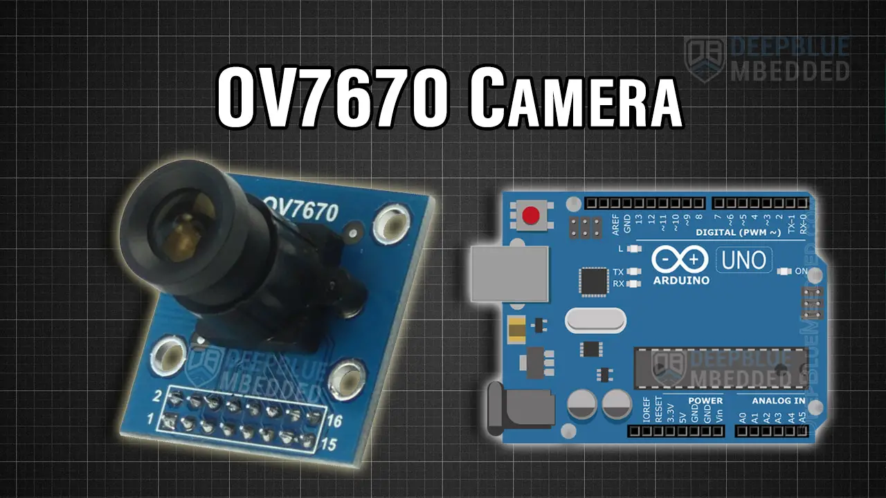
Arduino OV7670 Camera Interfacing
The OV7670 is a low-cost image sensor module that captures photos and videos up to 30 FPS. It is popular for DIY electronics projects like surveillance systems, robotics vision, or image-based applications. Ideally, you’d want a more powerful microcontroller board than an Arduino UNO (Atmega328p running @ 20MHz).
Boards like (Arduino Nano 33 BLE, ESP32, RP2040W) are all better suited for such application and all of them are IoT-capable boards making it easier to stream the camera’s data for a lot more possibilities.
However, in this tutorial, we’ll be interfacing the OV7670 camera with an Arduino UNO and sending the image frames over serial UART to a PC application where we’ll view the captured images/videos.
OV7670 Camera

The OV7670 camera module is a CMOS camera sensor capable of capturing images in RGB565 or YUV422 formats, which are ideal for microcontroller-based systems. However, interfacing the OV7670 with an Arduino UNO is a bit challenging due to the camera’s high data rate and lack of buffer memory to store the image frames.
Key Specifications of OV7670 Camera Module:
- Resolution: Up to 640×480 (VGA)
- Pixel Format: RGB565, YUV422
- Interface: 8-bit parallel data bus
- Operating Voltage: 3.3V
- Frame Rate: Up to 30 FPS (frames per second)
Buy an OV7670 Camera: you can find it here on ( Amazon, AliExpress, eBay )
Arduino OV7670 Wiring (Connection Diagram)
This is a summary of the connections needed between your Arduino UNO board and the OV7670 camera module.
| OV7670 | Arduino UNO | Description |
|---|---|---|
| VCC | 3.3V | Power supply |
| GND | GND | Ground |
| SIOC (SCL) | A5 (I2C Clock) | Serial Clock Line (SCL) |
| SIOD (SDA) | A4 (I2C Data) | Serial Data Line (SDA) |
| VSYNC | D2 | Vertical Synchronization |
| HREF | No Connection | Horizontal Synchronization |
| PCLK | D12 | Pixel Clock |
| XCLK (MCLK) | D3 | External Clock Input (D3 output is level-shifted to 3.3v with voltage divider resistors) |
| D0-D3 | A0-A3 | Parallel 8-bit Data Pins (0->3) |
| D4-D7 | D4-D7 | Parallel 8-bit Data Pins (4->7) |
| RESET | 3.3V | Reset |
| PWDN | GND | Power Down |
Here is the connection (wiring) diagram for the OV7670 Camera with Arduino UNO board.

The OV7670 Camera Module’s Pin (MCLK) is also referred to as (XCLK). This signal needs to be level-shifted from 5V down to 3.3V, which could be easily achieved with a voltage divider resistor network (3.3k and 4.7k) as shown in the circuit connection diagram above.
Arduino OV7670 Library Installation
The library we’ll use in this tutorial is called CameraOV7670, and this is how to install it on your system.
Step #1
Download the library folder from the attached zip file linked at the end of this tutorial.
Step #2
Copy the CameraOV7670 folder to your Arduino libraries directory. Which is usually under:
C:\Users\xxxxx\Documents\Arduino\libraries
And that’s all about it. Now we can use the library as we’ll do in the next two example projects.
Arduino OV7670 Code Example (Video Capture)
In this example project, we’ll capture video footage using Arduino UNO and the OV7670 camera module. The video frames are sent to our PC over serial port and a Java Application is used on the PC side to display the incoming image frames.
The wiring diagram for this example project is shown earlier in this tutorial. It’s better to re-check it again and go through the connections table one by one. However, I’ll show you the setup on my test bench. Soldering some connectors on a perfboard would make this look a bit more cleaner TBH.

Example Code
Here is the full code listing for this example.
|
1 2 3 4 5 6 7 8 9 10 11 12 13 14 15 16 |
* * LAB Name: Arduino OV7670 Camera (Video) Example * Author: Khaled Magdy * For More Info Visit: www.DeepBlueMbedded.com */ #include "OV7670_UART.h" void setup() { initializeScreenAndCamera(); } void loop() { processFrame(); } |
Note that the OV7670_UART.h header file is used to configure this demo application. By modifying the number in one line of code in that file, you can try different operating modes. In this demo example, I’ve used the (320×240 RGB @ 500kbps baud rate) Mode #5. Here are the other options that you can select from that header file:
|
1 2 3 4 5 6 7 8 9 10 11 12 13 14 15 16 17 18 19 |
// select resolution and communication speed: // 1 - 115200bps 160x120 rgb // 2 - 115200bps 160x120 grayscale // 3 - 500000bps 160x120 rgb // 4 - 500000bps 160x120 grayscale // 5 - 500000bps 320x240 rgb // 6 - 500000bps 320x240 grayscale // 7 - 1Mbps 160x120 rgb // 8 - 1Mbps 160x120 grayscale // 9 - 1Mbps 320x240 rgb // 10 - 1Mbps 320x240 grayscale // 11 - 1Mbps 640x480 grayscale // 12 - 2Mbps 160x120 rgb // 13 - 2Mbps 160x120 grayscale // 14 - 2Mbps 320x240 rgb // 15 - 2Mbps 320x240 grayscale // 16 - 2Mbps 640x480 rgb // 17 - 2Mbps 640x480 grayscale #define UART_MODE 5 |
PC App
In the attached download zip folder, you’ll also find a PC application (ArduImageCapture) that has 3 batch executables for (Windows, Linux, and Mac). Run the appropriate version according to your system’s OS. Select the Arduino board’s COM Port and Baud Rate, and click on the “Listen” button to start capturing the image data coming from the Arduino board & the OV7670 camera.

Testing Results
Here is the result of testing this project code example on my Arduino UNO board.
Any shaking in the camera’s position will result in severe image distortion as you might have noticed in the video shown above which I’ve captured while holding the camera module in my hand and pointing it to different objects on my test bench.
Arduino OV7670 Code Example (Image Capture)
In this example project, we’ll capture images using Arduino UNO and the OV7670 camera module. The images are sent to our PC over the serial port and a Java Application is used on the PC side to display the incoming image frames.
The wiring diagram for this example project is the same as before, just add a push button and hook it up to Arduino’s Pin 8.
Example Code
Here is the full code listing for this example.
|
1 2 3 4 5 6 7 8 9 10 11 12 13 14 15 16 17 18 19 20 |
/* * LAB Name: Arduino OV7670 Camera (Image) Example * Author: Khaled Magdy * For More Info Visit: www.DeepBlueMbedded.com */ #include "OV7670_UART.h" void setup() { initializeScreenAndCamera(); pinMode(8, INPUT_PULLUP); } void loop() { if(digitalRead(8) == LOW) { processFrame(); } } |
Testing Results
Here is the result of testing this project code example on my Arduino UNO board. Upon each button press event, an image is captured with the OV7670 camera and sent over the serial port to the PC application. Just like the previous example project, but it’s not automatically/continuously capturing and sending image frames. Instead, this demo example captures a single shot image upon button press event.

Required Parts List
Here is the full components list for all the parts you’d need to perform the practical LABs mentioned in this tutorial and the whole Arduino Programming series of tutorials found here on our website.
* Please, note that those are affiliate links and we’ll receive a small commission on your purchase at no additional cost to you, and it’d definitely support our work.
| QTY. | Component Name | Amazon.com | AliExpress | eBay |
| 1 | OV7670 Camera | Amazon | AliExpress | eBay |
| 1 | Arduino UNO Kit | Amazon | AliExpress | eBay |
| 1 | Complete Arduino Sensors/Modules Kit | Amazon | AliExpress | eBay |
| 1 | DC Power Supply | Amazon | AliExpress | eBay |
| 1 | BreadBoard | Amazon | AliExpress | eBay |
| 1 | LEDs Kit | Amazon & Amazon | AliExpress | eBay |
| 1 | Resistors Kit | Amazon & Amazon | AliExpress | eBay |
| 1 | Capacitors Kit | Amazon & Amazon | AliExpress & AliExpress | eBay & eBay |
| 1 | Jumper Wires Pack | Amazon & Amazon | AliExpress & AliExpress | eBay & eBay |
| 1 | Push Buttons | Amazon & Amazon | AliExpress | eBay |
| 1 | Potentiometers | Amazon | AliExpress | eBay |
★ Check The Links Below For The Full Course Kit List & LAB Test Equipment Required For Debugging ★
Download Tutorial’s Attachments
You can download all attachment files for this Article/Tutorial (project files, schematics, code, etc..) using the link below. Please consider supporting our work through the various support options listed in the link down below. Every small donation helps to keep this website up and running and ultimately supports the whole community.
Wrap Up
To conclude this tutorial, we’ve covered how to interface an OV7670 camera with an Arduino UNO, and capture images and videos with this camera module. You can build on top of the provided example projects and use the OV7670 camera with your Arduino boards.
If you’re just getting started with Arduino, you need to check out the Arduino Getting Started [Ultimate Guide] here.
And follow this Arduino Series of Tutorials to learn more about Arduino Programming.
References: