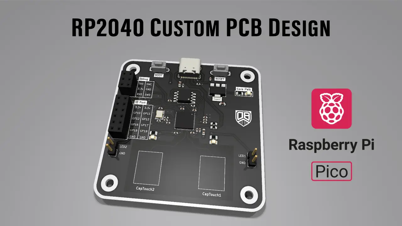
In this article, I’ll show you the Raspberry Pi Pico (RP2040) schematic & PCB design steps to make your own custom RP2040 PCB board. I’ll explain some of the design decisions I’ve made, how to prepare the files needed for manufacturing, and how to place the PCB SMT order at JLCPCB which is kindly sponsoring this project.
This is a custom RP2040 development board designed for evaluating the Raspberry Pi Pico RP2040 MCU. This project can serve as a baseline for anyone willing to create his own custom dev board based on the RP2040 microcontroller.
This Project is Sponsored By JLCPCB
Table of Contents
- RP2040 Overview & Datasheet
- Raspberry Pi Pico (RP2040) Board Schematic Design
- Placing PCBA Order @ JLCPCB
- Getting Started With Raspberry Pi Pico (RP2040) C/C++
- RP2040 LED Blinking GPIO Example Test
- RP2040 USB Serial Printf Example Test
- Getting Started With Raspberry Pi Pico (RP2040) Arduino
- Wrap Up
- RP2040 Schematic + PCB Design Project Video
RP2040 Overview & Datasheet
The RP2040 is a dual-core microcontroller designed by Raspberry Pi, featuring Dual ARM Cortex-M0+ processors running at up to 133MHz. It includes a rich set of peripherals such as ADC, DMA, PWM, Timers, Serial Communication interfaces, and PIO (Programmable I/O), which enable versatile hardware control and interfacing.
The RP2040 has a decent balance of performance, low power consumption, and affordability, making it ideal for DIY projects, education, and professional applications. Below is a block diagram of the microcontroller’s top-level architecture.

RP2040 Datasheet & Reference Manual
RP2040 Raspberry Pi Pico Datasheet
RP2040 Hardware Design Guidelines
Raspberry Pi Pico (RP2040) Board Schematic Design
This is the schematic design that I came up with for this Raspberry Pi Pico RP2040 development board project. Some parts are not mandatory and can be omitted for even more cost optimization if you need.
 Schemtatic Design in KiCAD")
1. DC PWR In + LDO + USB
There’s a USB-C port that I’m using for power input (+5v) as well as USB communication that’s required for UF2 flash programming of the Raspberry Pi Pico (RP2040) chip.
The USB +5v input is regulated down to 3.3v using an LDO. The +3.3v is then used to power up the RP2040 microcontroller and the internal LDO regulator that generates the +1.1v digital supply voltage.
2. RP2040 MCU Circuitry + QSPI FLASH
The RP2040 microcontroller requires a +3.3v input voltage @ IOVdd pin, +1.1v from the internal regulator that powers the DVDD, 100nF decoupling capacitors, and a 12MHz crystal oscillator.
Unlike most microcontrollers in the market, the RP2040 doesn’t have an internal flash memory. Therefore, an external Quad-SPI (QSPI) flash chip is required. You can add a 2MB, 4MB, 8MB, or 16MB flash chip.
On my board, I’ve used the maximum flash size allowed by the RP2040’s XIP (eXcute-In-Place) interface which is 16MB (128Mbit).
I’ve also added a RESET button to reset the microcontroller when needed. And we’ll need it every time we try to flash a new firmware to the chip. For UF2 programming, a BOOT button is also needed on the QSPI CS line.
3. SWD Debug Port
To debug the ARM cores on the RP2040 microcontroller, a serial wire debug interface can be routed to a pin header on your dev board. Typically, it’ll include: (+3.3v, GND, SWD, SWCLK).
4. IO Port + LEDs
Just pin-out all the IO pins you need to one or two headers depending on your desired board shape and layout.
For my board, I’ve added a power indicator LED + 2x user-programmable LEDs.
Placing PCBA Order @ JLCPCB
Finally, we’re ready to generate the fabrication files and send them to JLCPCB for PCB fabrication and assembly. For this task, I use the KiCAD plugin named “Fabrication Toolkit”. With just one button click, you’ll have all manufacturing output files ready in a new folder that’s automatically created for you by the plugin toolkit.

1. Upload Your Gerber File & Check PCB Fab. Options
The next step is to upload your PCB Gerber files and modify the PCB fabrication options as needed in your project. Just keep an eye on the price because some options are not considered as a standard fabrication process, which will end up costing you a bit more and take a bit more time to get fabricated.
Even if you’re 100% sure that your design & fabrication files are flawless, the online system & JLCPCB or any other fab house can still pick up incorrect components’ orientation or placement. Always double-check the PCB component placement after uploading your files.
2. Upload BOM & CPL Files
The next step is to upload your design’s BOM file and the components positions file (CPL) to JLCPCB and let it check the files and report the stock status and total number of components to be assembled, their cost, and so on.

Check everything and make sure the components are selected correctly from the JLCPCB SMT library. And also double-check the component placements on the next page and correct any wrong rotations in the CPL file. There is a mismatch between the KiCAD output position file & JLCPCB’s system, so it does pick up wrong orientations for some ICs, diodes, etc. Always double-check everything before placing the order.
3. Pay To Place Your Order
The last step to place your order is to pay for the invoice and you can apply any valid discount coupon at this step to reduce the cost.
4. Wait For Delivery & Prepare For Testing!
You should expect to receive your board within 4 days to 1 week depending on where you live.
Here is how it turned out at the end.

Getting Started With Raspberry Pi Pico (RP2040) C/C++
To get started with Raspberry Pi Pico RP2040 MCU development in C/C++ SDK, you first need to install the required toolchain. The tutorial linked below is a very detailed guide that will help you get started with embedded C development for the RP2040 microcontroller.
")
This tutorial is the ultimate guide for getting started with Raspberry Pi Pico using C/C++ SDK. You’ll learn how to install the Pico C/C++ SDK toolchain, create a project from scratch, and build/flash your Embedded-C/C++ projects to the Raspberry Pi Pico (RP2040-based) boards.
RP2040 LED Blinking GPIO Example Test
This is the first test example project in which we’ll blink the onboard 2x LEDs alternatively for half a second each.
Open the Pico-Visual Studio Code software, create a new project, and copy the example test code below. The exact project creation steps are demonstrated in detail in this tutorial: Raspberry Pi Pico RP2040 GPIO Tutorial (C/C++ SDK)
RP2040 LED Blinking GPIO Example Code
The Application Code For This Example (main.c)
/*
 * LAB Name: Raspberry Pi Pico Digital Inputs & Outputs (C/C++ SDK)
 * Author: Khaled Magdy
 * For More Info Visit: www.DeepBlueMbedded.com
*/
#include "pico/stdlib.h"

#define LED1_PIN 22
#define LED2_PIN 23

int main()
{
    gpio_init(LED1_PIN);
    gpio_init(LED2_PIN);
    gpio_set_dir(LED1_PIN, GPIO_OUT);
    gpio_set_dir(LED2_PIN, GPIO_OUT);
    while (1)
    {
        gpio_put(LED1_PIN, 0);
        gpio_put(LED2_PIN, 1);
        sleep_ms(500);
        gpio_put(LED1_PIN, 1);
        gpio_put(LED2_PIN, 0);
        sleep_ms(500);
    }
}
Compile & Flash the firmware to the board using the UF2 bootloader.
LED Blinking Test Result
")
This article will give more in-depth information about GPIO digital input output pins in Raspberry Pi Pico (RP2040) using C/C++ SDK. With a couple of code examples & simulations for digital pin read and write operations.
RP2040 USB Serial Printf Example Test
In this test project, we’ll do serial print using USB CDC on the Raspberry Pi Pico RP2040 microcontroller.
Open the Pico-Visual Studio Code software, create a new project, and copy the example test code below. The exact project creation steps are demonstrated in detail in this tutorial: Raspberry Pi Pico USB Serial Print Tutorial (C/C++ SDK)
RP2040 USB Serial Print Example Code
The Application Code For This Example (main.c)
/* * LAB Name: Raspberry Pi Pico USB CDC Serial Print * Author: Khaled Magdy * For More Info Visit: www.DeepBlueMbedded.com */ #include#include "pico/stdlib.h" int main() { stdio_init_all(); while (1) { printf("Hello World From Pi Pico USB CDC\n"); sleep_ms(100); } }
Compile & Flash the firmware to the board using the UF2 bootloader.
RP2040 USB Serial Print Test Result


This article will give more in-depth information about USB serial print in Raspberry Pi Pico (RP2040) using C/C++ SDK. With a couple of code examples & simulations for sending serial messages from the RP2040 over USB to PC and displaying the data on a serial terminal and plotting numeric data on a serial plotter GUI.
Getting Started With Raspberry Pi Pico (RP2040) Arduino
To get started with Raspberry Pi Pico RP2040 MCU development in Arduino C++ inside the Arduino IDE, you first need to install the RP2040 core within your locally installed version of Arduino IDE. The tutorial linked below is a very detailed guide that will help you get started with Arduino code development for the RP2040 microcontroller.
")
This tutorial is the ultimate guide for getting started with Raspberry Pi Pico (RP2040) using Arduino IDE. You’ll also learn how to simulate your Arduino code on the RP2040 using the Wokwi simulation environment.
Wrap Up
By the end of this, you should have learned how to create your custom Raspberry Pi Pico RP2040 dev board or incorporate this microcontroller in your next project if needed.
The intention behind designing this board that I’ve shown you today is to evaluate the possibility of using a cheap MCU like the RP2040 for touching sensing applications using the CVD algorithm/technique. This could significantly offload the CapTouch sensors sampling task from the main application processor.
Unfortunately, the RP2040’s ADC performance in this specific area did not meet my expectations. Surprisingly, It’s even marginally worse than the CH32V003 RISC-V MCU by WCH. Don’t get me wrong on this, It’ll just work fine but it won’t serve my niche application needs.