In this tutorial, we’ll discuss the Raspberry PI Pico GPIO Digital Input Read & Output Write functions using C/C++ SDK. We’ll also create a Pico C/C++ SDK demo project from scratch to experiment with the Raspberry Pi Pico digital input output pins operation. This tutorial is compatible with the Raspberry Pi Pico W board and any RP2040-based board as well.
This tutorial will address the Raspberry Pi Pico GPIO digital read and write functions using the Pico C/C++ SDK programming. You can find navigation buttons on the left sidebar to go to the Raspberry Pi Pico tutorials series using the programming language you prefer instead.
Table of Contents
- Raspberry Pi Pico Digital Input & Output Pins
- Raspberry Pi Pico C/C++ SDK GPIO Functions
- Pi Pico Digital Output Write (C/C++ SDK)
- Pi Pico Digital Input Read (C/C++ SDK)
- Raspberry Pi Pico LED + Button Example (C/C++ SDK)
- Pi Pico LED + Button C SDK Example Simulation
- Concluding Remarks
Raspberry Pi Pico Digital Input & Output Pins
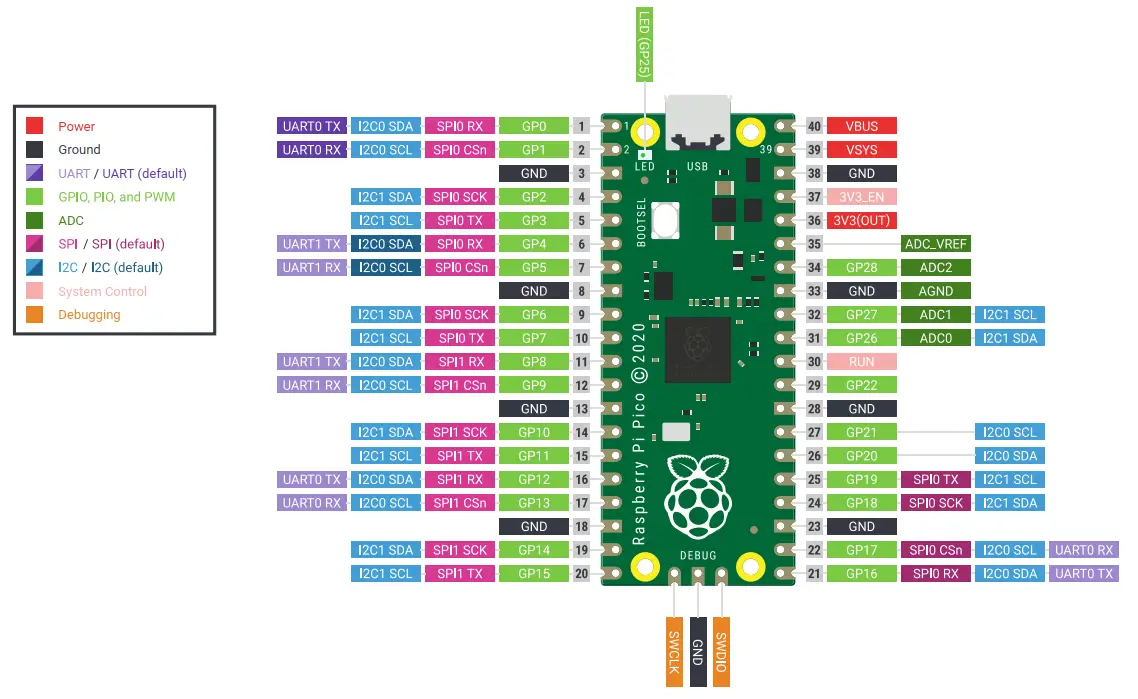
The GPIO (General-Purpose Input Output) Pins are the digital IO pins of the Raspberry Pi Pico board. There are 26 GPIO pins on the Raspberry Pi Pico board highlighted in light green color in the pinout diagrams below. (right-click on the images below and select “open image in a new tab” for the full-resolution)
Raspberry Pi Pico Pinout
Raspberry Pi Pico W Pinout
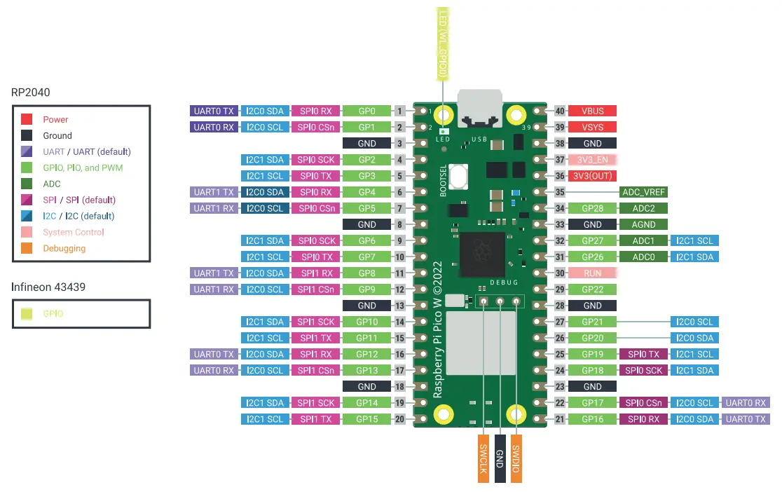
The Pins from GPIO0 To GPIO29 are the GPIO pins of the RP2040 microcontroller. With the exception of the following four pins that have dedicated special functions which we’ll explain hereafter: GPIO23, GPIO24, GPIO25 and GPIO29.
Raspberry Pi Pico Pin Voltage
In output mode, the Raspberry Pi Pico digital pin voltage is:
- 3.3v (when the digital pin is set HIGH)
- 0v (when the digital pin is set to LOW).
In input mode, the Raspberry Pi Pico digital input pin will read a 0 or 1 depending on the voltage applied to the pin:
- 0v–0.8v: read as 0 (logic 0 or LOW)
- 2v–3.3v: read as 1 (logic 1 or HIGH)
Any voltage level between 0.8v-2v is considered an undefined input for the digital IO pin.
Raspberry Pi Pico Pin Current
The Raspberry Pi Pico IO pins are able to source or sink up to 50mA of current combined. This is the maximum absolute current that can be sourced from or sunk to all Raspberry Pi Pico GPIO pins at any given time. The default drive strength for each single GPIO pin is 4mA.
Raspberry Pi Pico GPIO pins have programmable drive strength per individual IO pin. You can choose the drive strength for an IO pin: 2mA, 4mA, 8mA, or 12mA. The actual current depends on the load connected to the pin, the Raspberry Pi Pico (RP2040) will do its best to drive the IO pin to HIGH(3.3v) or LOW(0v) given the drive strength you’ve selected.
The Raspberry Pi Pico GPIO pins are able to source or sink up to a maximum of 12mA of current per pin. The combined GPIO pins’ total current should not exceed 50mA at any given time.
Special Function GPIO Pins (Non-Usable)
There are 4 GPIO pins that are not “Freely” usable on the Raspberry Pi Pico board. They are not exposed because they’re used to control some features on the Pi Pico board itself. Those pins are as follows:
GPIO23 | Controls the onboard SMPS power save enable pin |
GPIO24 | VBUS Sense; HIGH if VBUS is present, Else LOW |
GPIO25 | Connected to the onboard LED |
GPIO29 | Used by The ADC to measure the VSYS |
This article will give more in-depth information about the Raspberry Pi Pico GPIO pins and their functionalities. And how to choose the suitable pins for whatever functionality you’re trying to achieve and know the fundamental limitations of the device with some workaround tips and tricks.
Raspberry Pi Pico C/C++ SDK GPIO Functions
The Raspberry Pi Pico C/C++ SDK has a handful of APIs (functions) that let you control the behavior of GPIO pins. Those functions are used for initializing and controlling the RP2040 GPIO pins.
gpio_init(uint gpio)
The gpio_init() function is used to initialize a single GPIO line (pin) to be used as a software-controlled IO pin. After initializing a GPIO pin using the gpio_init() function, we can set it as an input or output pin using the set direction function which is described below.
gpio_set_dir(uint gpio, bool mode)
The gpio_set_dir()function is used to configure a single GPIO line (pin) as an input or output pin. By setting the bool mode parameter to 1 (true), the pin is set to output. Setting the mode to 0 (false), the GPIO pin will be set as an input pin.
Once a GPIO pin is initialized and set as an input or output pin, we can use the gpio_put() and gpio_get() functions to write or read the digital pin state.
bool gpio_get(uint gpio)
Reads the pin digital state (High or Low) of an input pin.
gpio_put(uint gpio, bool value)
Sets the digital pin state of an output pin (High or Low).
Pi Pico Digital Output Write (C/C++ SDK)
This is how to perform a digital output pin write on the Raspberry Pi Pico (or any RP2040-based) board with the Pico C/C++ SDK. In the following example code, I’m setting the GPIO pin number 5 as an output pin and writing High & Low to the pin with a time delay of 100ms after each pin write operation.
|
1 2 3 4 5 6 7 8 9 10 11 12 |
int main() { gpio_init(5); gpio_set_dir(5, GPIO_OUT); while (1) { gpio_put(LED_PIN, 1); sleep_ms(100); gpio_put(LED_PIN, 0); sleep_ms(100); } } |
Pi Pico Digital Input Read (C/C++ SDK)
This is how to perform a digital input pin read on the Raspberry Pi Pico (or any RP2040-based) board with the Pico C/C++ SDK. In the following example code, I’m setting the GPIO pin number 5 as an output pin and pin number 6 as an input pin. Then, I read the pin state of the input pin and set the output pin accordingly, to control the output pin# 5 using the input from pin# 6.
|
1 2 3 4 5 6 7 8 9 10 11 12 13 14 15 |
int main() { gpio_init(5); gpio_set_dir(5, GPIO_OUT); gpio_init(6); gpio_set_dir(6, GPIO_IN); while (1) { while(gpio_get(6)) { gpio_put(5, 1); } gpio_put(5, 0); } } |
Raspberry Pi Pico LED + Button Example (C/C++ SDK)
Let’s now create a Raspberry Pi Pico C/C++ SDK project from scratch to practice the GPIO digital pin input & output operations. In this example, we’ll set a GPIO pin as an input pin and attach it to a push button. And we’ll use another GPIO pin as an output to an LED. While the button is held down, the LED should be turned ON, otherwise, it’ll be OFF.
It’s highly recommended to check out this tutorial (Getting Started With Raspberry Pi Pico Using C/C++ SDK), especially for setting up the development environment and creating a new project from scratch.
Step #1
Create the project folder LED_BUTTON and a main.c source code file. This is the source code to paste into the main.c file.
(This code can be used on both Raspberry Pi Pico & Pico W boards)
|
1 2 3 4 5 6 7 8 9 10 11 12 13 14 15 16 17 18 19 20 21 22 23 24 25 |
/* * LAB Name: Raspberry Pi Pico Digital Inputs & Outputs (C/C++ SDK) * Author: Khaled Magdy * For More Info Visit: www.DeepBlueMbedded.com */ #include "pico/stdlib.h" #define LED_PIN 20 #define BTN_PIN 21 int main() { gpio_init(LED_PIN); gpio_set_dir(LED_PIN, GPIO_OUT); gpio_init(BTN_PIN); gpio_set_dir(BTN_PIN, GPIO_IN); while (1) { while(gpio_get(BTN_PIN)) { gpio_put(LED_PIN, 1); } gpio_put(LED_PIN, 0); } } |
Step #2
Create and add the CMakeLists.txt file to the project’s folder. This is the CMake code to paste into the CMakeLists.txt file.
(Copy the CMake code that suits your board, whether it’s a Raspberry Pi Pico or Pico W board)
Raspberry Pi Pico
|
1 2 3 4 5 6 7 |
cmake_minimum_required(VERSION 3.13) include(pico_sdk_import.cmake) project(LED_BUTTON C CXX ASM) pico_sdk_init() add_executable(main main.c) pico_add_extra_outputs(main) target_link_libraries(main pico_stdlib) |
Raspberry Pi Pico W
|
1 2 3 4 5 6 7 8 |
cmake_minimum_required(VERSION 3.13) set(PICO_BOARD pico_w) include(pico_sdk_import.cmake) project(LED_BUTTON_W C CXX ASM) pico_sdk_init() add_executable(main main.c) target_link_libraries(main pico_stdlib) pico_add_extra_outputs(main) |
Step #3
Copy the file named ( pico_sdk_import.cmake ) CMake source file from the pico-sdk/external folder into your new project’s folder. The new project’s folder should now look like the one shown below.

Step #4
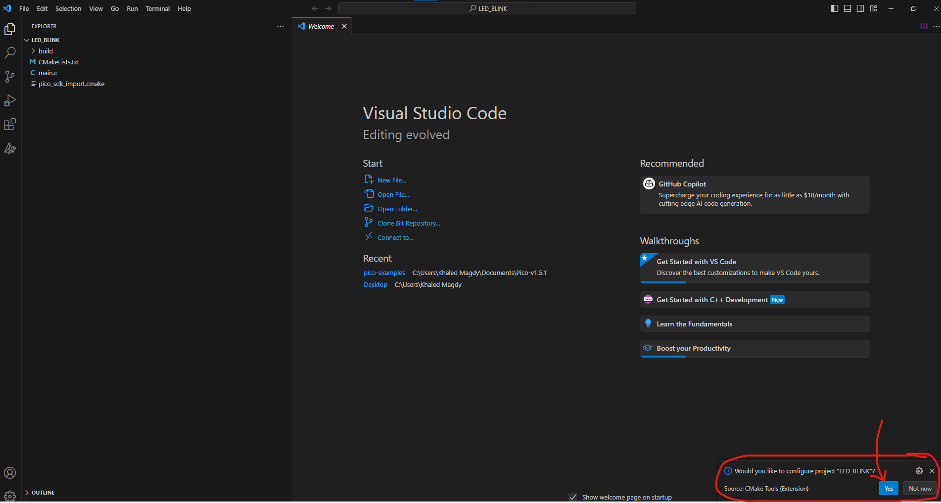
Open the “Pico – Visual Studio Code” shortcut launcher from the desktop of the start menu (recently added software). Select File > Open Folder. Navigate to where your new project’s folder is located and choose that folder.
VS Code will prompt you at the bottom of the IDE’s window to configure the project’s folder for you, select ‘yes’, and let it do that for you.
Step #5
Start the build process using the build button or from the top menu select Terminal > Run Build Task. Wait tell completion and you should get an output message like the one shown below, it also shows you the path for the output files. Ideally, you should find everything in the build folder inside the project folder that we’ve created.

Step #6
Let’s now flash the new project firmware to the Raspberry Pi Pico board. Hold the BOOTSEL button of the Raspberry Pi Pico board before connecting it to the USB port of your PC. While holding the BOOTSEL button, connect the Raspberry Pi Pico to your PC’s USB port.
It’ll boot in the bootloader mode and your PC will detect it as a USB storage device, so you’re now free to release the BOOTSEL button.
Drag and drop the UF2 output file to the Raspberry Pi Pico USB drive. It’ll take a couple of seconds to load, then it’ll automatically reboot and start running the new firmware that we’ve flashed to the RP2040 microcontroller.
Project Demo
If you’re using a Raspberry Pi Pico W board, the only difference you need to take care of is the CMake code in the CMakeLists.txt file. You’ll find a download link near the end of this tutorial for the same project replicated for both the Pi Pico & Pico W boards.
Pi Pico LED + Button C SDK Example Simulation
This is the simulation result for the previous Raspberry Pi Pico (And Pico W) LED_BUTTON example project (C/C++ SDK) using Wokwi Simulator. You can find the Project Simulation files linked below, so you can save a copy of it into your Wokwi projects dashboard and play around with the simulator environment.
- (Raspberry Pi Pico) LED + Button Project Simulation (C/C++ SDK)
- (Raspberry Pi Pico W) LED + Button Project Simulation (C/C++ SDK)
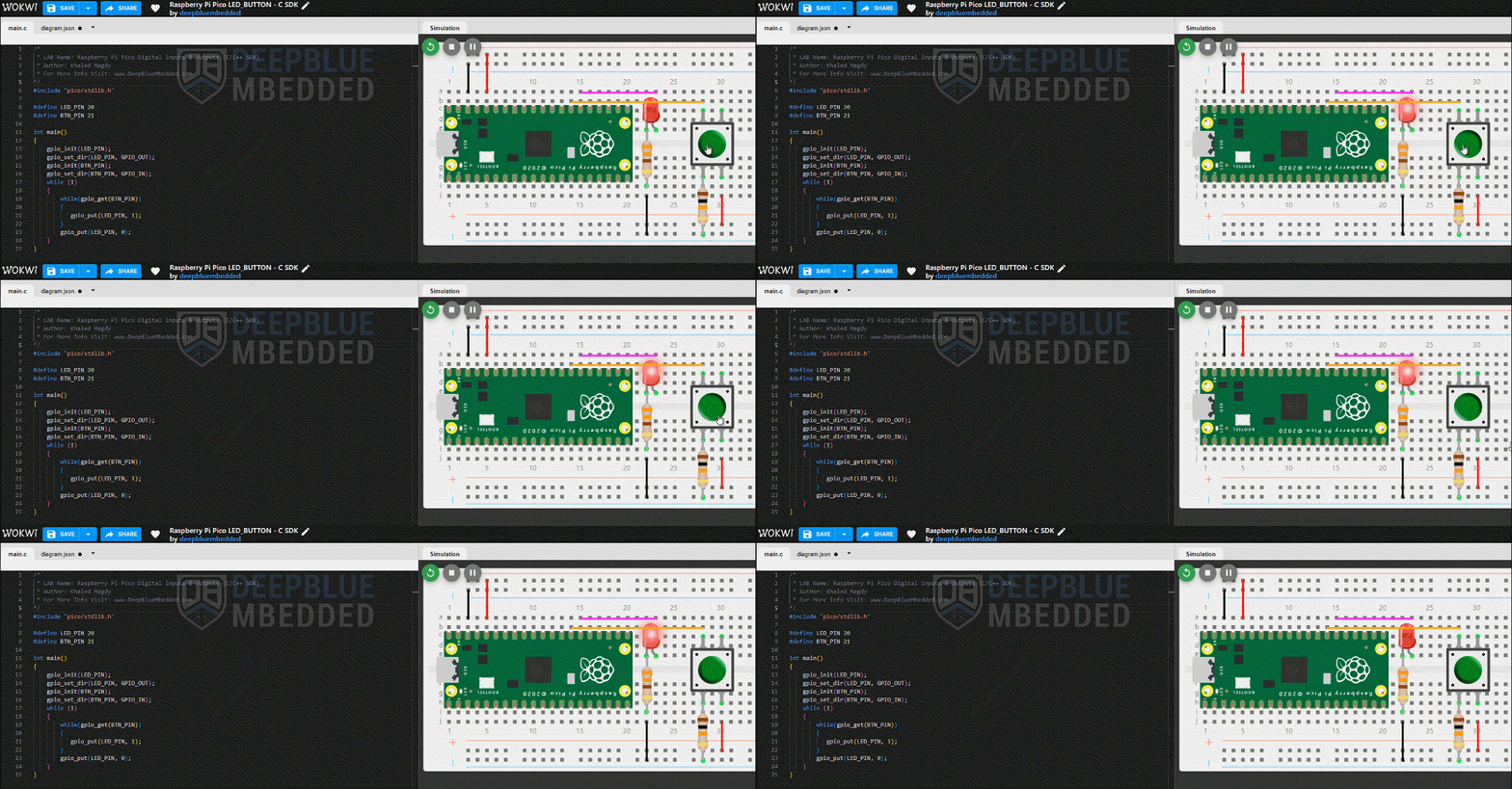
Simulating your Raspberry Pi Pico projects can be really helpful especially when you’re just getting started. This step is not mandatory at all, however, running your projects in a simulator environment will help you catch and fix some logic errors in the code or in the circuit wiring connections. Below is a complete guide tutorial for simulating your Raspberry Pi Pico (And Pico W) projects using Wokwi simulator.
This article will provide more in-depth information about simulating Raspberry Pi Pico projects using the online Wokwi simulator tool. You’ll learn how to simulate MicroPython, CircuitPython, Arduino C++, and C SDK projects on Raspberry Pi Pico.
You can download all attachment files for this Article/Tutorial (project files, schematics, code, etc..) using the link below. Please consider supporting my work through the various support options listed in the link below. Every small donation helps to keep this website up and running and ultimately supports our community.
If you’re looking forward to playing around with the Raspberry Pi Pico board to test its capabilities and features, you may just need to get a single board. Just like this one here. However, if you’d like to follow along with the Raspberry Pi Pico series of tutorials published here on our website, you may consider getting the following items:
2x Pi Pico Boards, 2x Pi Pico W Boards, 4x BreadBoards, Resistors, LEDs, Buttons, Potentiometers, etc. The reason behind getting multiple boards is that we’ll be using one board as a PicoProbe debugger for SWD debugging activities. And at least 2x Pico W boards for IoT wireless applications.
The full kit list of the Raspberry Pi Pico series of tutorials is found at the link below, as well as some test equipment for debugging that you may consider getting for your home electronics LAB.
Concluding Remarks
To conclude this tutorial, we’ve discussed how to initialize and configure the Raspberry Pi Pico digital input/output pins using the C/C++ SDK APIs (functions). And how to use the gpio_put() and gpio_get() functions to write and read a specific GPIO pin.
Follow this Raspberry Pi Pico Series of Tutorials to learn more about Raspberry Pi Pico Programming in different programming languages’ environments.
If you’re just starting with Raspberry Pi Pico, you should check out the following getting-started guides with the programming language you favor the most. There are 4 variants of the Raspberry Pi Pico tutorials to match your needs and help you along the path that you’re going to choose.
