In this tutorial, we’ll discuss the Raspberry PI Pico Serial Over USB functions using C/C++ SDK. We’ll also create a Raspberry Pi Pico Serial Print & Read Projects (C/C++ SDK). We’ll touch on the usage of the Serial Monitor and Serial Plotter with Raspberry Pi Pico as well. This tutorial is compatible with the Raspberry Pi Pico W board and any RP2040-based board.
This tutorial will address the Raspberry Pi Pico Serial Print & Read functions using the Pico C/C++ SDK programming. You can find navigation buttons on the left sidebar to go to the Raspberry Pi Pico tutorials series using the programming language you prefer instead.
Table of Contents
- Raspberry Pi Pico Serial Over USB
- Raspberry Pi Pico Serial Print (C/C++ SDK)
- Raspberry Pi Pico Serial Monitor (C/C++ SDK)
- Raspberry Pi Pico Serial Plotter (C/C++ SDK)
- Raspberry Pi Pico Serial Print Example (C/C++ SDK)
- Raspberry Pi Pico Serial Print Example Simulation
- Raspberry Pi Pico Serial Plotter Example (C/C++ SDK)
- Concluding Remarks
Raspberry Pi Pico Serial Over USB
The Raspberry Pi Pico (RP2040) microcontroller has 2x UART modules for serial communication: UART0 and UART1. The UART (RX & TX) pins are remappable, which means you can route the (RX or TX) signals internally to different GPIO pins of the microcontroller. However, the Default UART0 Pins: GPIO0 (TX) and GPIO1 (RX). We can definitely use UART0 or UART1 for serial communication with a PC.
However, the Raspberry Pi Pico (RP2040) microcontroller also has a native hardware USB module that we can use (in CDC class) to act as a serial port which will be detected by any PC as a Virtual COM Port. That’s what we’re going to use in this tutorial, since using a UART module will require a USB-TTL converter to communicate with a PC which is a little bit less convenient to use compared to the USB port.
Raspberry Pi Pico Serial Print (C/C++ SDK)
1. Enable stdio Over USB
To enable serial print (over USB CDC) in your Raspberry Pi Pico C/C++ SDK project, you need to edit the CMakeLists.txt file by adding the following two lines of code:
|
1 2 |
pico_enable_stdio_usb(main 1) pico_enable_stdio_uart(main 0) |
Which will therefore enable the stdio functions over USB instead of UART. main here is the name of the main.c executable c-code file, you can definitely change it to suit your main executable file name. But it’s recommended to name your main executable c-code file as main.c which is the standard naming convention in Embedded-C projects.
Check the tutorial linked below to help you get started with Raspberry Pi Pico with C/C++ SDK, create a new project from scratch, and learn more about the CMakeLists.txt file that we’ve just mentioned.
This tutorial is the ultimate guide for getting started with Raspberry Pi Pico using C/C++ SDK. You’ll learn how to install the Pico C/C++ SDK toolchain, create a project from scratch, and build/flash your Embedded-C/C++ projects to the Raspberry Pi Pico (RP2040-based) boards.
2. stdio printf() Function
After enabling the stdio functions over USB in the CMakeLists.txt file as we’ve done in the previous step, we’ll now be able to use the printf() function to send formatted strings of text over the USB serial port to the PC.
The printf() function can be used to print only text messages and/or formatted strings of text that include a mixture of characters, integer numbers, floating-point numbers, etc.
Printing Text-Only Messages
Here is an example of printing a text-only message string over the USB serial port.
|
1 2 3 4 5 6 7 8 9 10 11 12 13 |
#include <stdio.h> #include "pico/stdlib.h" int main() { stdio_init_all(); while (1) { printf("Hello World From Pi Pico USB CDC\n"); sleep_ms(100); } } |
Printing Text+Integer Numbers
Here is another example for printing (text + integer) messages over the USB serial port.
|
1 2 3 4 5 6 7 8 9 10 11 12 13 14 15 |
#include <stdio.h> #include "pico/stdlib.h" int counter = 0; int main() { stdio_init_all(); while (1) { printf("CounterValue = %d\n", counter); counter++; sleep_ms(100); } } |
Printing Text+Float Numbers
You can also use it to print (text + floating-point numbers) as in the following example (using the %f float-specifier flag).
|
1 2 3 4 5 6 7 8 9 10 11 12 13 14 |
#include <stdio.h> #include "pico/stdlib.h" float pi = 3.1415926; int main() { stdio_init_all(); while (1) { printf("Pi Value = %f\n", pi); sleep_ms(100); } } |
3. stdio scanf() Function
Similar to the printf() function, the scanf() function is used to read a formatted string from the stdin. You should use this function only if the incoming serial data is sent in a fixed format. Otherwise, you can use the gets() function to read a line string of unknown text format that you can parse or process thereafter according to your application’s needs.
Here is an example of reading a numeric value over the USB serial port and using that value to control an LED to turn ON/OFF.
|
1 2 3 4 5 6 7 8 9 10 11 12 13 14 15 16 17 18 19 20 |
#include <stdio.h> #include "pico/stdlib.h" #define LED_PIN 20 int LED_STATE = 0; int main() { gpio_init(LED_PIN); gpio_set_dir(LED_PIN, GPIO_OUT); stdio_init_all(); while (1) { printf("Enter 1 or 0 To Turn LED ON or OFF:\n"); scanf("%d", &LED_STATE); gpio_put(LED_PIN, LED_STATE); sleep_ms(100); } } |
4. stdio gets() Function
The gets(char* str) function reads a line from stdin and stores it into the string pointed to by str. It stops when either the newline character is read or when an EOF is reached, whichever comes first.
5. stdio puts() Function
The puts(char* str) function writes a string to stdout up to but not including the null character. A newline character is appended to the output string.
Raspberry Pi Pico Serial Monitor (C/C++ SDK)
A serial monitor is a GUI application that you can run on your PC to communicate with embedded microcontroller devices over the serial port. You can use the integrated Serial Monitor in Arduino IDE or any other serial terminal application that runs on your operating system (like TeraTerm or Putty).
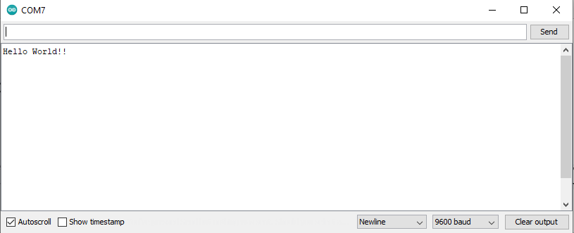
Using a serial monitor is really helpful for debugging Raspberry Pi Pico projects by sending the value of variables and flags to check them in real time using the serial monitor.
Using the Raspberry Pi Pico’s USB for serial print/read operations is not affected by the Baud Rate setting in your Serial Monitor application. You can leave it as 9600bps, 115200, or anything else. It just doesn’t matter while using USB CDC (Virtual COM Port).
Raspberry Pi Pico Serial Plotter (C/C++ SDK)
The Arduino Serial Plotter is another handy tool that’s also built into the Arduino IDE. It enables you to plot variables sent over the serial communication port and have a graphical visualization of the variable’s value over time. However, you can still use any other serial plotting application instead in case you don’t have the Arduino IDE installed on your PC.
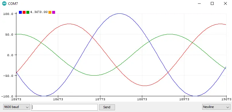
Using the serial plotter with Raspberry Pi Pico can be really helpful for debugging or monitoring the behavior of your code. Especially things that show weird timing behavior or if you’re trying to catch some runtime bugs. Showing a graphical plot for different values & flags over time can be extremely helpful.
Raspberry Pi Pico Serial Print Example (C/C++ SDK)
Let’s now create a Raspberry Pi Pico Serial Print/Read example project with the C/C++ SDK. In this example, we’ll set a GPIO pin as an output to an LED. And we’ll enable stdio operations over USB instead of UART. A string message prompt will be printed out to the user and we’ll get an integer input from the user (0 or 1) to control the output LED status (ON/OFF).
It’s highly recommended to check out this tutorial (Getting Started With Raspberry Pi Pico Using C/C++ SDK), especially for setting up the development environment and creating a new project from scratch.
Step #1
Create the project folder HELLO_WORLD and a main.c source code file. This is the source code to paste into the main.c file.
(This code can be used on both Raspberry Pi Pico & Pico W boards)
|
1 2 3 4 5 6 7 8 9 10 11 12 13 14 15 16 17 18 19 20 21 22 23 24 25 |
/* * LAB Name: Raspberry Pi Pico Hello World Serial Print & Read (C/C++ SDK) * Author: Khaled Magdy * For More Info Visit: www.DeepBlueMbedded.com */ #include <stdio.h> #include "pico/stdlib.h" #define LED_PIN 20 int LED_STATE = 0; int main() { gpio_init(LED_PIN); gpio_set_dir(LED_PIN, GPIO_OUT); stdio_init_all(); while (1) { printf("Hello World From Pi Pico USB CDC! Enter 1 or 0 To Turn LED ON or OFF:\n"); scanf("%d", &LED_STATE); gpio_put(LED_PIN, LED_STATE); sleep_ms(100); } } |
Step #2
Create and add the CMakeLists.txt file to the project’s folder. This is the CMake code to paste into the CMakeLists.txt file.
(Copy the CMake code that suits your board, whether it’s a Raspberry Pi Pico or Pico W board)
Raspberry Pi Pico
|
1 2 3 4 5 6 7 8 9 10 |
cmake_minimum_required(VERSION 3.13) include(pico_sdk_import.cmake) project(HELLO_WORLD C CXX ASM) pico_sdk_init() add_executable(main main.c) target_link_libraries(main pico_stdlib) pico_enable_stdio_usb(main 1) pico_enable_stdio_uart(main 0) pico_add_extra_outputs(main) |
Raspberry Pi Pico W
|
1 2 3 4 5 6 7 8 9 10 |
cmake_minimum_required(VERSION 3.13) set(PICO_BOARD pico_w) include(pico_sdk_import.cmake) project(HELLO_WORLD_W C CXX ASM) pico_sdk_init() add_executable(main main.c) target_link_libraries(main pico_stdlib) pico_enable_stdio_usb(main 1) pico_enable_stdio_uart(main 0) pico_add_extra_outputs(main) |
Step #3
Copy the file named ( pico_sdk_import.cmake ) CMake source file from the pico-sdk/external folder into your new project’s folder. The new project’s folder should now look like the one shown below.

Step #4
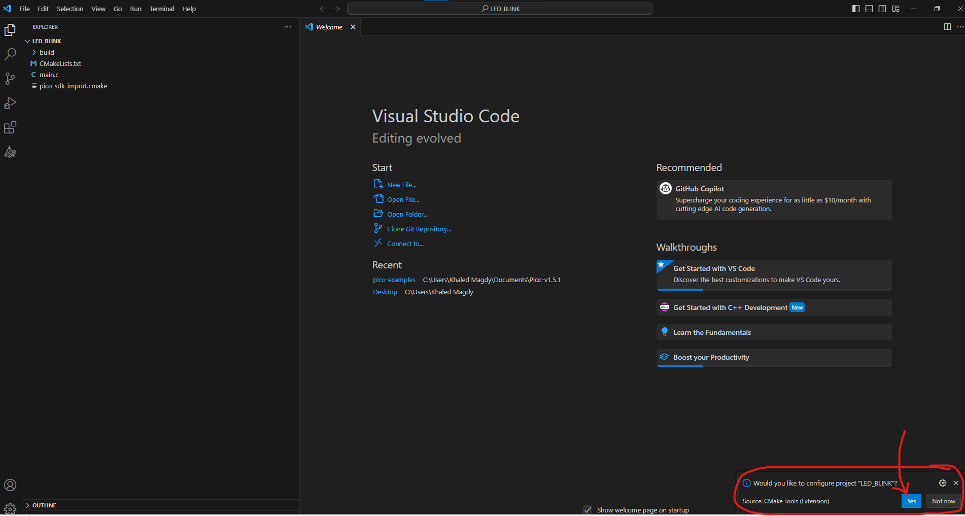
Open the “Pico – Visual Studio Code” shortcut launcher from the desktop or from the Windows start menu (type in search: “Pico – Visual Studio Code”). Select File > Open Folder. Navigate to where your new project’s folder is located and choose that folder.
VS Code will prompt you at the bottom of the IDE’s window to configure the project’s folder for you, select ‘yes’, and let it do that for you.
Step #5
Start the build process using the build button or from the top menu select Terminal > Run Build Task. Wait tell completion and you should get an output message like the one shown below, it also shows you the path for the output files. Ideally, you should find everything in the build folder inside the project folder that we’ve created.

Step #6
Let’s now flash the new project firmware to the Raspberry Pi Pico board. Hold the BOOTSEL button of the Raspberry Pi Pico board before connecting it to the USB port of your PC. While holding the BOOTSEL button, connect the Raspberry Pi Pico to your PC’s USB port.
It’ll boot in the bootloader mode and your PC will detect it as a USB storage device, so you’re now free to release the BOOTSEL button.
Drag and drop the main.uf2 output file to the Raspberry Pi Pico USB drive. It’ll take a couple of seconds to load, then it’ll automatically reboot and start running the new firmware that we’ve flashed to the RP2040 microcontroller.
While testing this demo project, you may not catch the first printed message on your serial monitor and it’ll show up as a blank window screen. That’s fine, it’s just waiting for your input value “1” or “0” to set the LED’s pin, print the prompt message again, and keep repeating.
Raspberry Pi Pico Serial Print Example Simulation
This is the simulation result for the previous Raspberry Pi Pico (And Pico W) HELLO_WORLD serial print/read example project (C/C++ SDK) using the Wokwi Simulator. You can find the Project Simulation files linked below, so you can save a copy of it into your Wokwi projects dashboard and play around with the simulator environment.
- (Raspberry Pi Pico) Serial Print/Read Project Simulation (C/C++ SDK)
- (Raspberry Pi Pico W) Serial Print/Read Project Simulation (C/C++ SDK)
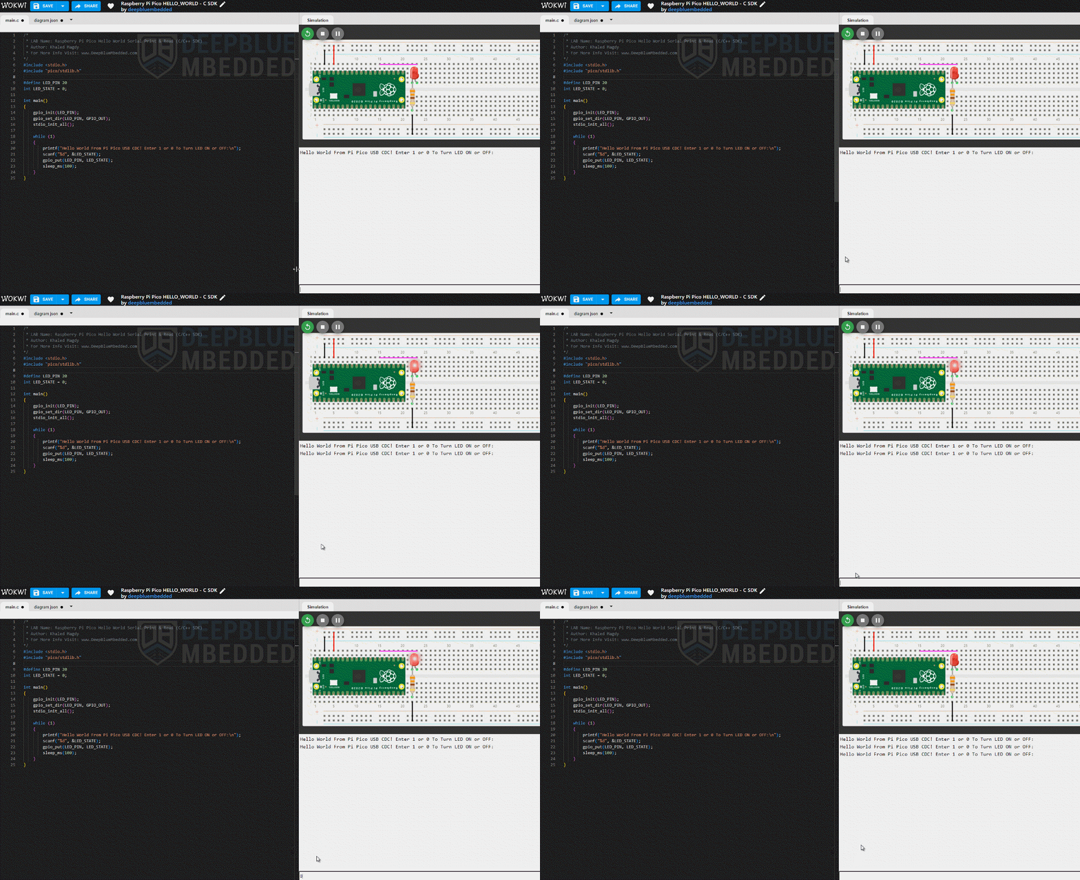
Simulating your Raspberry Pi Pico projects can be really helpful especially when you’re just getting started. This step is not mandatory at all, however, running your projects in a simulator environment will help you catch and fix some logic errors in the code or in the circuit wiring connections. Below is a complete guide tutorial for simulating your Raspberry Pi Pico (And Pico W) projects using the Wokwi simulator.
This article will provide more in-depth information about simulating Raspberry Pi Pico projects using the online Wokwi simulator tool. You’ll learn how to simulate MicroPython, CircuitPython, Arduino C++, and C SDK projects on Raspberry Pi Pico.
Raspberry Pi Pico Serial Plotter Example (C/C++ SDK)
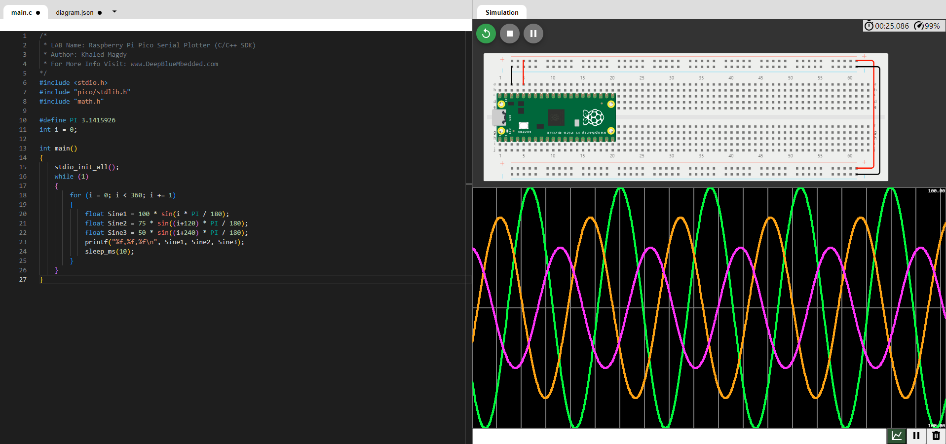
In this example project, we’ll use the serial plotter with Raspberry Pi Pico to plot 3x floating-point values that represent 3-phase sine waves with different amplitude & 120° of phase shift between them.
Note: The variables need to be comma-separated and line termination needs to be added at the end of the data points string to be plotted each time.
The project creation steps are exactly the same as the previous “ HELLO_WORLD” project, however, this new “ SERIAL_PLOTTER” project will have the following source code ( main.c).
|
1 2 3 4 5 6 7 8 9 10 11 12 13 14 15 16 17 18 19 20 21 22 23 24 25 26 27 |
/* * LAB Name: Raspberry Pi Pico Serial Plotter (C/C++ SDK) * Author: Khaled Magdy * For More Info Visit: www.DeepBlueMbedded.com */ #include <stdio.h> #include "pico/stdlib.h" #include "math.h" #define PI 3.1415926 int i = 0; int main() { stdio_init_all(); while (1) { for (i = 0; i < 360; i += 1) { float Sine1 = 100 * sin(i * PI / 180); float Sine2 = 75 * sin((i+120) * PI / 180); float Sine3 = 50 * sin((i+240) * PI / 180); printf("%f,%f,%f\n", Sine1, Sine2, Sine3); sleep_ms(10); } } } |
Here is the result after building this project and flashing it to my Raspberry Pi Pico Board. Note that I’m using the Arduino Serial Plotter GUI tool.

You can also use the Wokwi Simulator’s Serial Plotter Tool to get the same results (in a simulation environment) if you’d like to simulate your project before doing a real-life test on your hardware Raspberry Pi Pico board. Here is the simulation result for this “ SERIAL_PLOTTER” project.
The link below will direct you to the Wokwi simulation file for this Raspberry Pi Pico Serial Plotter project example (C/C++ SDK).
(Raspberry Pi Pico) Serial Plotter Project Simulation (C/C++ SDK)
You can download all attachment files for this Article/Tutorial (project files, schematics, code, etc..) using the link below. Please consider supporting my work through the various support options listed in the link below. Every small donation helps to keep this website up and running and ultimately supports our community.
If you’re looking forward to playing around with the Raspberry Pi Pico board to test its capabilities and features, you may just need to get a single board. Just like this one here. However, if you’d like to follow along with the Raspberry Pi Pico series of tutorials published here on our website, you may consider getting the following items:
2x Pi Pico Boards, 2x Pi Pico W Boards, 4x BreadBoards, Resistors, LEDs, Buttons, Potentiometers, etc. The reason behind getting multiple boards is that we’ll be using one board as a PicoProbe debugger for SWD debugging activities. And at least 2x Pico W boards for IoT wireless applications.
The full kit list of the Raspberry Pi Pico series of tutorials is found at the link below, as well as some test equipment for debugging that you may consider getting for your home electronics LAB.
Concluding Remarks
To conclude this tutorial, we’ve discussed how to enable serial over USB for the Raspberry Pi Pico microcontrollers. We’ve also created a serial print & read project example with Raspberry Pi Pico using C/C++ SDK, and we’ve tested the usage of Serial Monitor & Serial Plotter with the Raspberry Pi Pico for debugging and testing various projects.
Follow this Raspberry Pi Pico Series of Tutorials to learn more about Raspberry Pi Pico Programming in different programming languages’ environments.
If you’re just starting with Raspberry Pi Pico, you should check out the following getting-started guides with the programming language you favor the most. There are 4 variants of the Raspberry Pi Pico tutorials to match your needs and help you along the path that you’re going to choose.



Thank you!
This article was precise, clear, and understandable.
(And it WORKED!)
Glad You Found it Helpful!