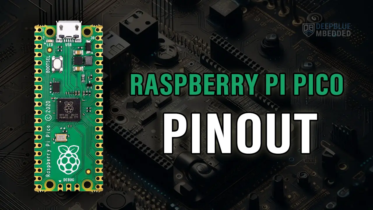
The Raspberry Pi Pico & Pico W boards have 26 pins that you can use for various applications. In this tutorial, we’ll explore the Raspberry Pi Pico Pinout and break down each section of pins to discuss their functionality and usage. You’ll learn how to use the Raspberry Pi Pico Pins in your project and get a solid understanding of a lot of the hardware capabilities of the RP2040 microcontroller.
Moreover, you’ll also get the Raspberry Pi Pico & Pico W pinout diagrams and the schematic diagram that you can use to create your own RP2040 PCB board with any custom modifications that you’d need for your project. Without further ado, let’s get right into it!
Table of Contents
- Raspberry Pi Pico Pinout Guide
- Raspberry Pi Pico & Raspberry Pi Pico W
- Raspberry Pi Pico Pinout Diagram
- Raspberry Pi Pico W Pinout Diagram
- Raspberry Pi Pico Pins Functions
- Raspberry Pi Pico Power Pins
- Raspberry Pi Pico System Control Pins
- Raspberry Pi Pico GPIO Pins (Digital IO)
- Raspberry Pi Pico Interrupt Pins (GPIO IRQ)
- Raspberry Pi Pico PWM Pins
- Raspberry Pi Pico SWD Debugging Pins
- Raspberry Pi Pico Analog Pins (ADC)
- Raspberry Pi Pico UART Pins
- Raspberry Pi Pico I2C Pins
- Raspberry Pi Pico SPI Pins
- Raspberry Pi Pico Board Auxiliaries
- Raspberry Pi Pico Schematic Diagram
- Concluding Remarks
Raspberry Pi Pico Pinout Guide
In the previous tutorial (Getting Started With Raspberry Pi Pico), we discussed the Raspberry Pi Pico development ecosystem, we also prepared the development & prototyping environments, and we were able to develop and test our first getting started project.
In this tutorial, we’ll get a closer look at the Raspberry Pi Pico pinout and discuss the usage for each pin and its intended functionality. We’ll mainly address the following points:
- Raspberry Pi Pico Pinout Diagram
- What are the Raspberry Pi Pico pins you can use?
- What are their functionalities in detail?
- Some examples & use cases for each set of Raspberry Pi Pico pins
Despite the fact that this article’s main focus is Raspberry Pi Pico Pinout, it is still however very useful for all other variations of RP2040-based development boards. Especially the Raspberry Pi Pico & Pico W.
Raspberry Pi Pico & Raspberry Pi Pico W
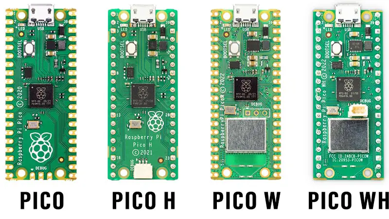
There are two Raspberry Pi Pico boards that you can get depending on your project’s need for WiFi/Bluetooth connectivity:
- Raspberry Pi Pico: No WiFi/Bluetooth
- Raspberry Pi Pico W: Has WiFi & Bluetooth 5.2
Those two Raspberry Pi Pico boards can come to you with or without pin headers pre-soldered to the board. The version with a pin header soldered has an “H” letter in the name. The entire Raspberry Pi Pico boards family is shown below.
Raspberry Pi Pico Pinout Diagram
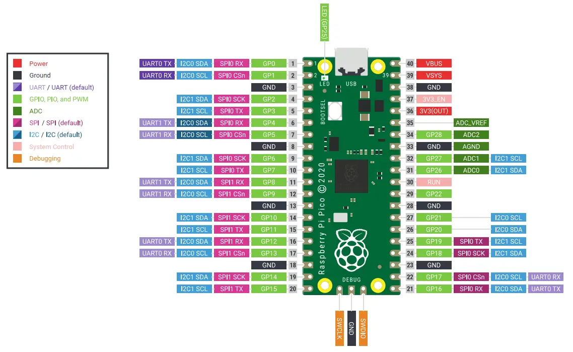
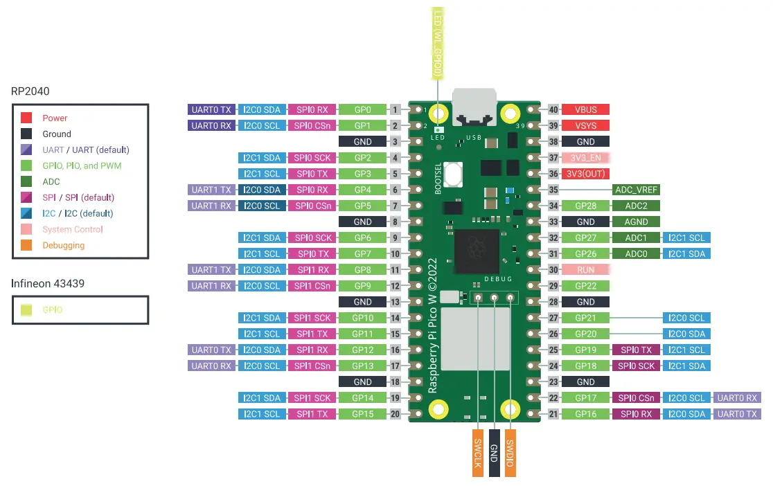
Here is a detailed Raspberry Pi Pico Pinout Diagram with colored labels and legends to help you easily identify the functionalities that each pin can perform. You can right-click and open it in a new tab to view the full-resolution image and/or download it to your computer for reference.
Raspberry Pi Pico W Pinout Diagram
Here is a detailed Raspberry Pi Pico W Pinout Diagram with colored labels and legends to help you easily identify the functionalities that each pin can perform. You can right-click and open it in a new tab to view the full-resolution image and/or download it to your computer for reference.
Raspberry Pi Pico Pins Functions
Only 26 pins of the 40 pins of the Raspberry Pi Pico board are GPIO pins that can be used for IO operations, the rest are for power and debugging purposes. The 40 pins of the Raspberry Pi Pico are divided into the following groups based on the hardware functionality they’re used for.
- Power Pins
- System Control Pins
- 26x Digital GPIO Pins
- 26x GPIO IRQ Interrupt Pins
- 16x PWM Channels
- 3x ADC Analog Input Pins
- 2x UART Pins
- 2x SPI Pins
- 2x I2C Pins
- SWD Debug Port
We’ll discuss each pin group in the following sections one by one in more detail.
Raspberry Pi Pico Power Pins
The Raspberry Pi Pico board has an SMPS (Switching Mode Power Supply) voltage regulator that provides a regulated DC voltage of +3.3v to power up the main RP2040 microcontroller. You can also use the power pins to power up external modules and sensors that you’d like to use with your Pi Pico board.
There are multiple options when it comes to powering up your Raspberry Pi Pico board that we’ll discuss in detail hereafter in this section. Here is a figure for the power section on your Raspberry Pi Pico board with a detailed pinout for each power pin and its functionality.
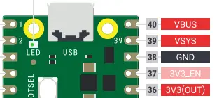
VBUS is the micro-USB 5v which is a DC voltage output. If you’re powering your Pi Pico board via USB, you can use this pin to supply 5v to external sensors and modules from your Pi Pico board. Try not to overload it with heavy loads.
VSYS is the system external power input pin (voltage: 1.8v to 5.5v) that feeds into the onboard SMPS which generates a 3.3v that supplies the main RP2040 microcontroller and all logic circuits on the board.
3V3(OUT) is the 3.3v power output that can be used to power up various modules, sensors, and other external circuits.
GND pins are highlighted in black in the pinout diagram shown above. The Raspberry Pi Pico board has 8 ground pins that you can use while connecting external devices like LEDs, Sensors, Modules, etc.
Never forget to connect all ground pins of your circuits to the same ground line (always have common ground) as long as those circuits are required to communicate with each other. External sensors and modules not only need the 5v or 3.3v voltage supply, but they also have to have the same ground line shared by the Raspberry Pi Pico in order to communicate properly.
Raspberry Pi Pico System Control Pins
There are two system control pins on the Raspberry Pi Pico board highlighted in light red color. Those pins are as follows:
3V3_EN is the Enable pin for the onboard SMPS which generates the 3.3v that powers up the RP2040 microcontroller. Pull this pin LOW to power-down the Raspberry Pi Pico board. By default, it’s enabled.
RUN is the core RESET pin. Pull this pin to LOW in order to reset the RP2040 microcontroller. By default, it’s enabled (HIGH).
Raspberry Pi Pico GPIO Pins (Digital IO)
The GPIO (General-Purpose Input Output) Pins are the digital IO pins of the Raspberry Pi Pico board. There are 26 GPIO pins on the Raspberry Pi Pico board highlighted in light green color in the pinout diagrams.
The Pins from GPIO0 To GPIO29 are the GPIO pins of the RP2040 microcontroller. With the exception of the following four pins that have dedicated special functions which we’ll explain hereafter: GPIO23, GPIO24, GPIO25 and GPIO29.
Raspberry Pi Pico Pin Voltage
In output mode, the Raspberry Pi Pico digital pin voltage is:
- 3.3v (when the digital pin is set HIGH)
- 0v (when the digital pin is set to LOW).
In input mode, the Raspberry Pi Pico digital input pin will read a 0 or 1 depending on the voltage applied to the pin:
- 0v–0.8v: read as 0 (logic 0 or LOW)
- 2v–3.3v: read as 1 (logic 1 or HIGH)
Any voltage level between 0.8v-2v is considered an undefined input for the digital IO pin.
Raspberry Pi Pico Pin Current
The Raspberry Pi Pico IO pins are able to source or sink up to 50mA of current combined. This is the maximum absolute current that can be sourced from or sunk to all Raspberry Pi Pico GPIO pins at any given time. The default drive strength for each single GPIO pin is 4mA.
Raspberry Pi Pico GPIO pins have programmable drive strength per individual IO pin. You can choose the drive strength for an IO pin: 2mA, 4mA, 8mA, or 12mA. The actual current depends on the load connected to the pin, the Raspberry Pi Pico (RP2040) will do its best to drive the IO pin to HIGH(3.3v) or LOW(0v) given the drive strength you’ve selected.
The Raspberry Pi Pico GPIO pins are able to source or sink up to a maximum of 12mA of current per pin. The combined GPIO pins’ total current should not exceed 50mA at any given time.
Special Function GPIO Pins (Non-Usable)
There are 4 GPIO pins that are not “Freely” usable on the Raspberry Pi Pico board. They are not exposed because they’re used to control some features on the Pi Pico board itself. Those pins are as follows:
GPIO23 | Controls the onboard SMPS power save enable pin |
GPIO24 | VBUS Sense; HIGH if VBUS is present, Else LOW |
GPIO25 | Connected to the onboard LED |
GPIO29 | Used by The ADC to measure the VSYS |
Raspberry Pi Pico Interrupt Pins (GPIO IRQ)
All GPIO pins of the Raspberry Pi Pico can be used as IRQ (Interrupt Request) pins. In other words, the Raspberry Pi Pico has 26 interrupt pins.
Interrupt pins are basically digital IO pins that can be configured to be in input mode. And will provide an interrupt signal directly to the CPU whenever the pin state changes. The CPU will pause the current operation, jump to a predefined interrupt handler function, and execute it till completion. Then it resumes the main loop() function (application).
Interrupt pins can provide a near-immediate response to external events like input pin state change and this can be really useful for different applications that include, but are not limited to, the following list:
- Motor Speed Measurement With Optical Encoder
- Proximity Sensor Interfacing
- Keypad Matrix Scanning
- Ultrasonic Sensor Interfacing
- and much more
Raspberry Pi Pico PWM Pins
All GPIO pins of the Raspberry Pi Pico can be used to output PWM signals. The Raspberry Pi Pico has 8 independent PWM generators, called slices. Each slice has two channels (A and B), which gives us a total of 16 PWM channels.
The 16 PWM channels can be mapped to any of the 26 GPIO pins on the Raspberry Pi Pico. Every two channels on the same slice will share the same time base (will output the same frequency) but with an individually controlled duty cycle.
| GPIO | 0 | 1 | 2 | 3 | 4 | 5 | 6 | 7 | 8 | 9 | 10 | 11 | 12 | 13 | 14 | 15 |
| PWM Channel | 0A | 0B | 1A | 1B | 2A | 2B | 3A | 3B | 4A | 4B | 5A | 5B | 6A | 6B | 7A | 7B |
| GPIO | 16 | 17 | 18 | 19 | 20 | 21 | 22 | 23 | 24 | 25 | 26 | 27 | 28 | 29 | ||
| PWM Channel | 0A | 0B | 1A | 1B | 2A | 2B | 3A | 3B | 4A | 4B | 5A | 5B | 6A | 6B |
A single PWM channel’s output can be routed (mapped) to two different GPIO pins and the same PWM signal will show up on both pins.
Raspberry Pi Pico SWD Debugging Pins
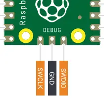
The SWD (Serial Wire Debug) Header is used for debugging your Raspberry Pi Pico (RP2040 microcontroller) projects.
We’ll discuss how to use this port to debug your Raspberry Pi Pico projects in a dedicated tutorial in the future.
Raspberry Pi Pico Analog Pins (ADC)
The ADC (Analog to Digital Converter) in the Raspberry Pi Pico (RP2040) is 12-bit in resolution. The ADC’s sampling rate is up to 500ksps.
The Pi Pico’s ADC has 5 channels, only 3 of which are freely usable.
The ADC channels’ pins are highlighted in dark green color in the pinout diagrams.

| GPIO Pin | ADC Channel | Function |
GPIO26 | ADC0 | Read ADC0 Channel |
GPIO27 | ADC1 | Read ADC1 Channel |
GPIO28 | ADC2 | Read ADC2 Channel |
GPIO29 | ADC3 | Measure Voltage @ VSYS |
| ——- | ADC4 | Read The Built-in Core Temperature Sensor |
The ADC is used to read analog voltage input and convert it to its digital representation. Given that the RP2040’s ADC is 12 bits in resolution, the digital output range is therefore from 0 up to 4095. The analog input range is from 0v up to 3.3v (which is the default analog reference voltage VREF = +3.3v).
You can use the interactive tool below to set an analog input voltage and see the ADC digital output value that corresponds to the analog input voltage. The output equation for the ADC is as follows: ADC Output = ( Analog input voltage / VREF ) x (2n – 1). Where VREF = 3.3v and n is the ADC resolution which is 12bits.
If you run out of ADC input pins, you can use an external analog switch (Mux) at the cost of extra digital control pins and a reduced ADC throughput. Using an external dedicated ADC chip is possible and sometimes preferred if your application needs a higher resolution of about 16 bits or higher.
ADC_VREF pin can be used to provide an external reference voltage for the analog-to-digital conversion of inputs to the analog pins. The reference voltage essentially specifies the maximum analog input voltage after which the ADC’s output will saturate at 4095.
Let’s recall the ADC’s output equation which is: ADC Output = ( Analog input voltage / VREF ) x (2n – 1). Where the “default” VREF = 3.3v and n is the ADC resolution which is 12bits.
Using the ADC_VREF pin we can change the default VREF voltage and set it to any desired voltage level which allows for more precise A/D conversions. Let’s say we hook up the ADC_VREF pin to an external 1.25v DC supply, we’ll end up having more than double the resolution of the default 3.3v analog reference.
The reason is: that instead of dividing the 0v-3.3v range into discrete 4095 digital levels, we’ll now divide the 0v-1.25v range into discrete 4095 digital levels. Which is more than double the default resolution. But you must make sure that the input analog voltage will not exceed 1.25v after setting the ADC_VREF to 1.25v. Otherwise, the ADC will saturate at 4095 if the analog input voltage exceeds the new ADC_VREF (1.25v).
Use the interactive tool above to try it yourself and see the effect of lowering the ADC_VREF voltage from 3.3v down to 1.25v and how it increases the ADC resolution by a factor of (2.64).
| VREF | Analog Input Voltage | ADC Digital Output |
| 3.3v | 0.001v (1mv) | 1 |
| 1.25v | 0.001v (1mv) | 3 |
For the exact same analog input (1mv), you get more ADC ticks (levels) at VREF=1.25v compared to VREF=3.3v. This is what we mean by the resolution being more than doubled (increased by a factor of 2.64).
Raspberry Pi Pico UART Pins
The Raspberry Pi Pico (RP2040) microcontroller has 2x UART modules for serial communication: UART0 and UART1. The UART (RX & TX) pins are remappable, which means you can route the (RX or TX) signals internally to different GPIO pins of the microcontroller. However, the Default UART0 Pins: GPIO0 (TX) and GPIO1 (RX).
Raspberry Pi Pico Default UART0 Pins: GPIO0 (TX) and GPIO1 (RX).
The following are the GPIO pins that can be used as UART (RX & TX) in the Raspberry Pi Pico (RP2040) microcontroller:
| UART Module | RX Pins | TX Pins |
| UART0 | GPIO1, GPIO13, GPIO17 | GPIO0, GPIO12, GPIO16 |
| UART1 | GPIO5, GPIO9 | GPIO4, GPIO8 |
Besides serial communication with your PC for debugging and such, the UART is also used for interfacing various sensors and modules such as:
- Bluetooth Modules
- GSM/GPRS Modules
- Lidar Sensors
- GPS Modules
- and much more
If you need extra UART modules in your application, you can use the Hardware PIO in RP2040 microcontrollers. Which is a very powerful feature that enables you to implement customized communication protocols like UART, SPI, QSPI, 1-Wire, and more. Which can operate at an amazingly high speed without adding any noticeable CPU load to your application.
Raspberry Pi Pico I2C Pins
The Raspberry Pi Pico (RP2040) microcontroller has 2x I2C modules: I2C0 and I2C1. The I2C (SDA & SCL) pins are remappable, which means you can route the (SDA or SCL) signals internally to different GPIO pins of the microcontroller. However, the Default I2C0 Pins: GPIO4 (SDA) and GPIO5 (SCL).
Raspberry Pi Pico Default I2C0 Pins: GPIO4 (SDA) and GPIO5 (SCL).
The following are the GPIO pins that can be used as I2C (SDA & SCL) in the Raspberry Pi Pico (RP2040) microcontroller:
| I2C Module | SDA Pins | SCL Pins |
| I2C0 | GPIO0, GPIO4, GPIO8, GPIO12, GPIO16, GPIO20 | GPIO1, GPIO5, GPIO9, GPIO13, GPIO17, GPIO21 |
| I2C1 | GPIO2, GPIO6, GPIO10, GPIO14, GPIO18, GPIO26 | GPIO3, GPIO7, GPIO11, GPIO15, GPIO19, GPIO27 |
There are so many modules and sensors that we can interface with the Raspberry Pi Pico using the I2C bus, which include:
- RTC Clock
- OLED Display Screens
- I2C IO Pins Expander
- External EEPROM Memory Chips
- MPU6050 IMU (Gyro+Accelerometer)
- and much more
In most cases, you won’t need more than one I2C module on your Raspberry Pi Pico microcontroller. If you need to add a new extra device to the I2C bus, it’s as simple as hooking it up to the SCL and SDA lines and you’re good to go, as long as it has a unique I2C device address.
This is a huge advantage for the I2C multi-master multi-slave bus compared to something like UART which is a single-master single-slave communication port.
The Raspberry Pi Pico (RP2040) microcontroller’s I2C supports the following three I2C standards: Standard Mode (data rate up to 100kbps), Fast Mode (up to 400kbps), and Fast Mode Plus (up to 1Mbps). The High-Speed Mode (up to 3.4Mbps), and Ultra-High Speed Mode (up to 5Mbps) both are not supported.
Raspberry Pi Pico SPI Pins
The Raspberry Pi Pico (RP2040) microcontroller has 2x SPI modules: SPI0 and SPI1. The SPI (RX, TX, SCK, and CS) pins are remappable, which means you can route the (RX, TX, SCK, and CS) signals internally to different GPIO pins of the microcontroller. However, the Default SPI0 Pins: GPIO16 (RX), GPIO19 (TX), GPIO18 (SCK), and GPIO17 (CS).
Raspberry Pi Pico Default SPI0 Pins: GPIO 16 (RX), GPIO19 (TX), GPIO18 (SCK), and GPIO17 (CS).
The following are the GPIO pins that can be used as SPI (RX, TX, SCK, and CS) in the Raspberry Pi Pico (RP2040) microcontroller:
| SPI Module | RX Pins | TX Pins | SCK Pins | CS Pins |
| SPI0 | GPIO0, GPIO4, GPIO16 | GPIO3, GPIO7, GPIO19 | GPIO2, GPIO6, GPIO18 | GPIO1, GPIO5, GPIO17 |
| SPI1 | GPIO8, GPIO12 | GPIO11, GPIO15 | GPIO10, GPIO14 | GPIO9, GPIO13 |
There are so many applications in which you’d need to use the Raspberry Pi Pico’s SPI bus to interface various sensors and modules which include, but are not limited to, the following examples:
- SPI TFT Display Interfacing
- Dot Matrix Display Interfacing
- External SPI Flash Memory
- External SPI ADC Modules
- nRF24L01 Wireless Modules
- and much more
As stated earlier, We’ll dedicate a separate in-depth tutorial for each serial communication protocol (UART – I2C – SPI). And we’ll create a handful of applications and example projects to practice what we’ll learn.
Raspberry Pi Pico Board Auxiliaries
Besides the main RP2040 microcontroller on the Raspberry Pi Pico board, we can also find some auxiliary parts that provide additional features & functionalities that we’ll go through in this section hereafter.
QSPI Flash
The Raspberry Pi Pico board has a 2Mbytes of QSPI Flash memory chip which provides plenty of space for your embedded applications. Compared to something like Arduino UNO which has 32Kbytes of flash memory, this new Raspberry Pi Pico board has a 64x times more program space.
USB Port
The Raspberry Pi Pico board has a USB port that’s used as a +5v power source and also data transfer (programming) just like most Arduino boards.
BOOTSEL Button
The Raspberry Pi Pico board has a BOOTSEL button that’s used for programming to boot the microcontroller in bootloader mode to do the flashing process. Then, you release that button and reset the microcontroller so it boots up in normal operation mode and starts executing the new firmware that you’ve flashed.
OnBoard LED
The Raspberry Pi Pico board has an onboard LED that’s user-programmable for debugging purposes and such.
OnBoard Temperature Sensor
The Raspberry Pi Pico has a built-in temperature sensor on the RP2040 silicon chip itself to provide a temperature reading of the RP2040 core itself. This sensor can be read on the ADC4 channel, and it doesn’t reflect the ambient temperature quite accurately because it’s not intended to do so.
WiFi / Bluetooth (Only Pi Pico W)
The Raspberry Pi Pico W board has onboard 2.4GHz WiFi/Bluetooth wireless interfaces support. The Pi Pico W’s Bluetooth 5.2 supports operating in BLE or Bluetooth Classic. The wireless connectivity makes the Pi Pico W board consume a lot more power compared to the Pi Pico which doesn’t have WiFi/Bluetooth.
Raspberry Pi Pico Schematic Diagram
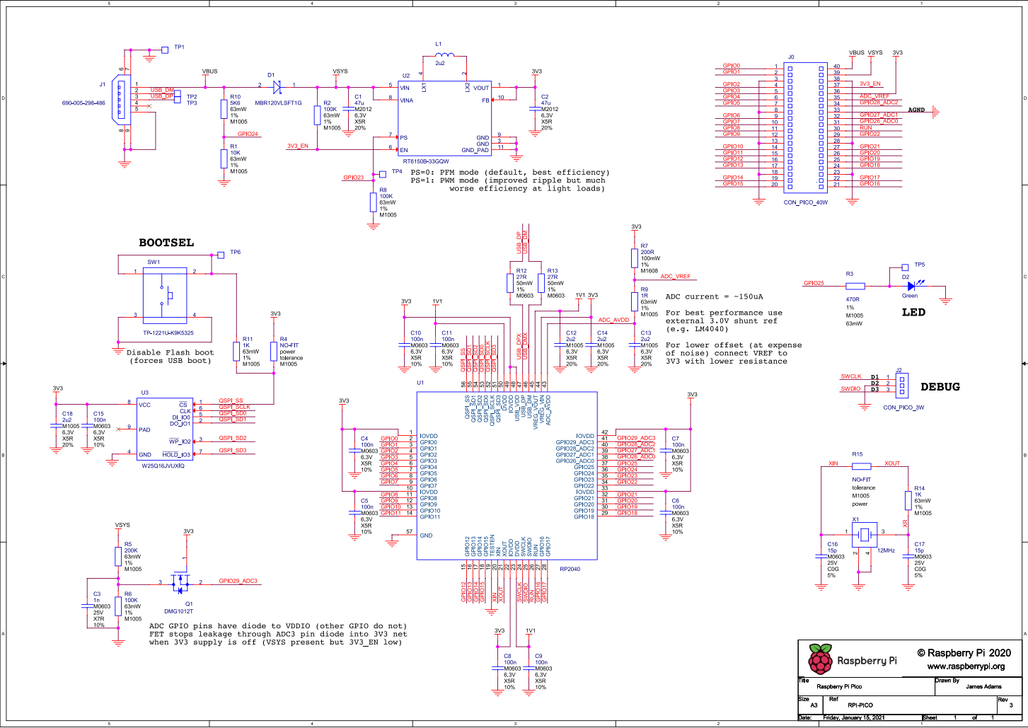
As an open-source project, the Raspberry Pi Pico board schematic design and parts list is completely open-source and available for everyone to download, modify, and create custom R2040 board designs based on it.
You’ll also get a much clearer view of the underlying hardware details by carefully studying the Raspberry Pi Pico board schematic design files. You can download the Raspberry Pi Pico schematic design diagram file using (this link, page24).
Concluding Remarks
To conclude this tutorial, we’ll highlight the fact that there are so many options for using the Raspberry Pi Pico pins and a unique set of features that each pin supports. We hope it’s been a helpful guide to helping you decide which pins to use for your project and what are the fundamental limitations and workarounds for each.
Follow this Raspberry Pi Pico Series of Tutorials to learn more about Raspberry Pi Pico Programming in different programming languages’ environments.
If you’re just getting started with Raspberry Pi Pico, you need to check out the Raspberry Pi Pico Getting Started Ultimate Guide below.
This is the ultimate guide for beginners getting started with Raspberry Pi Pico. It’ll help you learn the fundamentals of Hardware and software to understand the basics required to accelerate your learning journey with Raspberry Pi Pico Programming.
