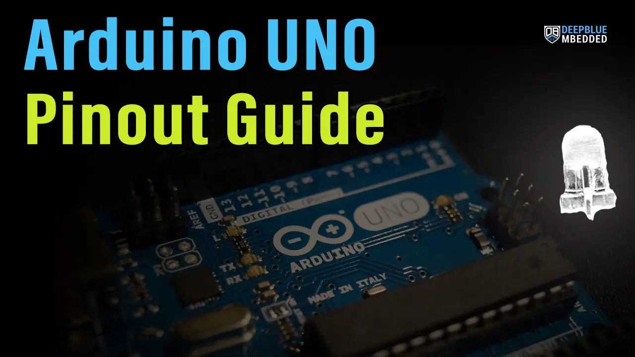
The Arduino UNO board has over 20 pins that you can use for various applications. In this tutorial, we’ll explore the Arduino UNO Pinout and break down each section of Arduino Pins to discuss its functionality and use in detail. You’ll learn how to use Arduino Pins in your project and get a solid understanding of a lot of Arduino fundamentals.
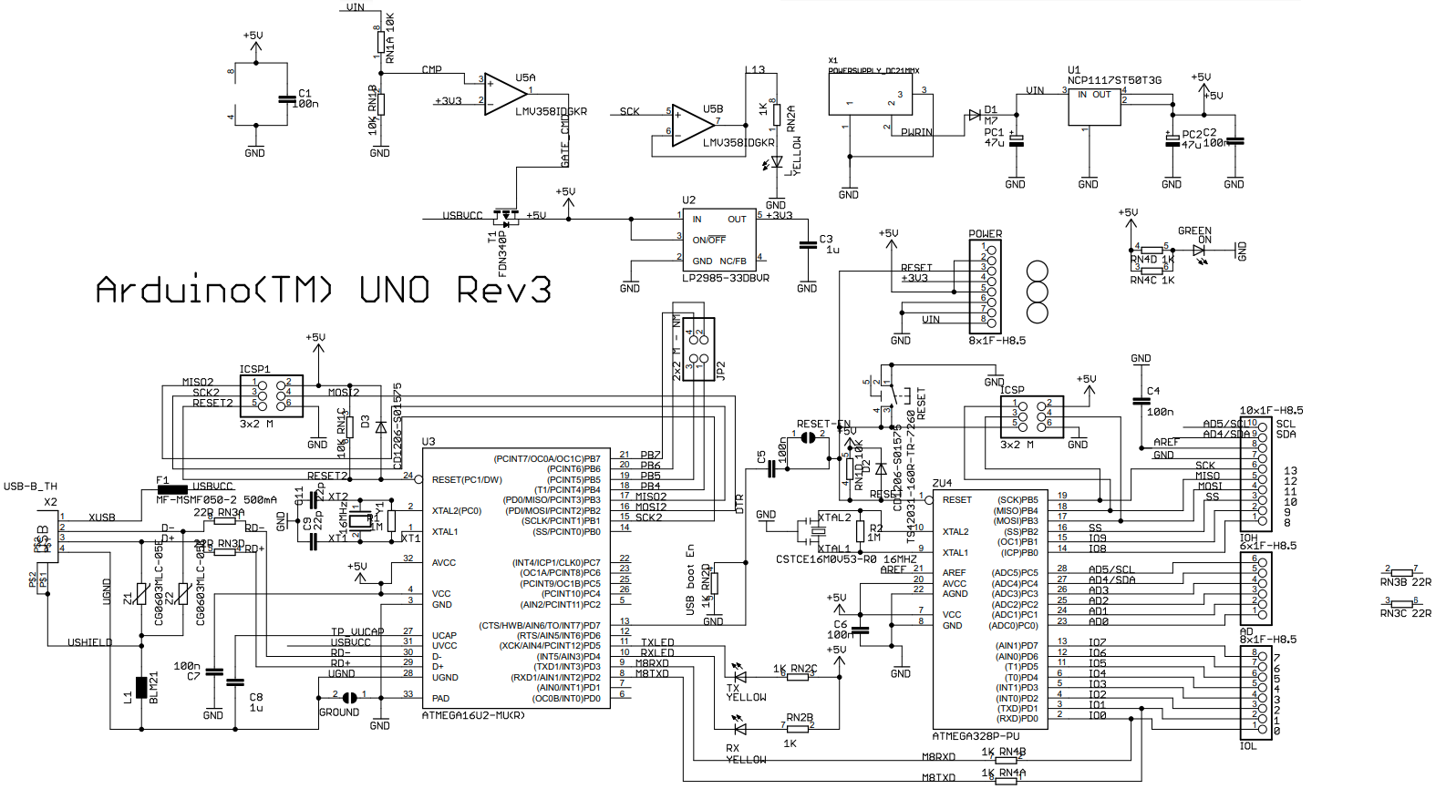
Moreover, you’ll also get the Arduino UNO pinout diagram and the Arduino R3 schematic diagram that you can use to create your own Arduino PCB board with any custom modifications that you’d need for your project. Without further ado, let’s get right into it!
Table of Contents
- Arduino UNO Pinout Guide
- Arduino UNO Pinout Diagram
- Arduino UNO Pinout – Power Pins
- Arduino UNO Pinout – Digital Pins
- Arduino UNO Pinout – Analog Pins
- Arduino UNO Pinout – Serial Ports Pins
- Arduino UNO Pinout Summary
- Arduino UNO R3 Schematic Diagram
- Get Started With Arduino UNO Pins
Arduino UNO Pinout Guide
In the previous tutorial (Getting Started With Arduino), we discussed a lot of Arduino Hardware/Software fundamentals and the Arduino Ecosystem, we also prepared the development/simulation/prototyping environments, and we were able to develop and test our first 3 beginner projects.
Now, we’ll get a closer look at the Arduino UNO pinout and discuss the usage for each pin and its intended functionality. So, in this tutorial you’ll mainly get the following points:
- Arduino UNO Pinout Diagram
- What are the Arduino pins you can use?
- What are their functionalities in detail?
- Some examples & use cases for each set of Arduino pins
Despite the fact that this article’s main focus is Arduino UNO Pinout, it actually is still however very useful for Arduino beginners with different Arduino boards. The knowledge and basics we’ll be discussing here are transferable to any other Arduino board even if it’s not AVR-based.
Arduino UNO Pinout Diagram
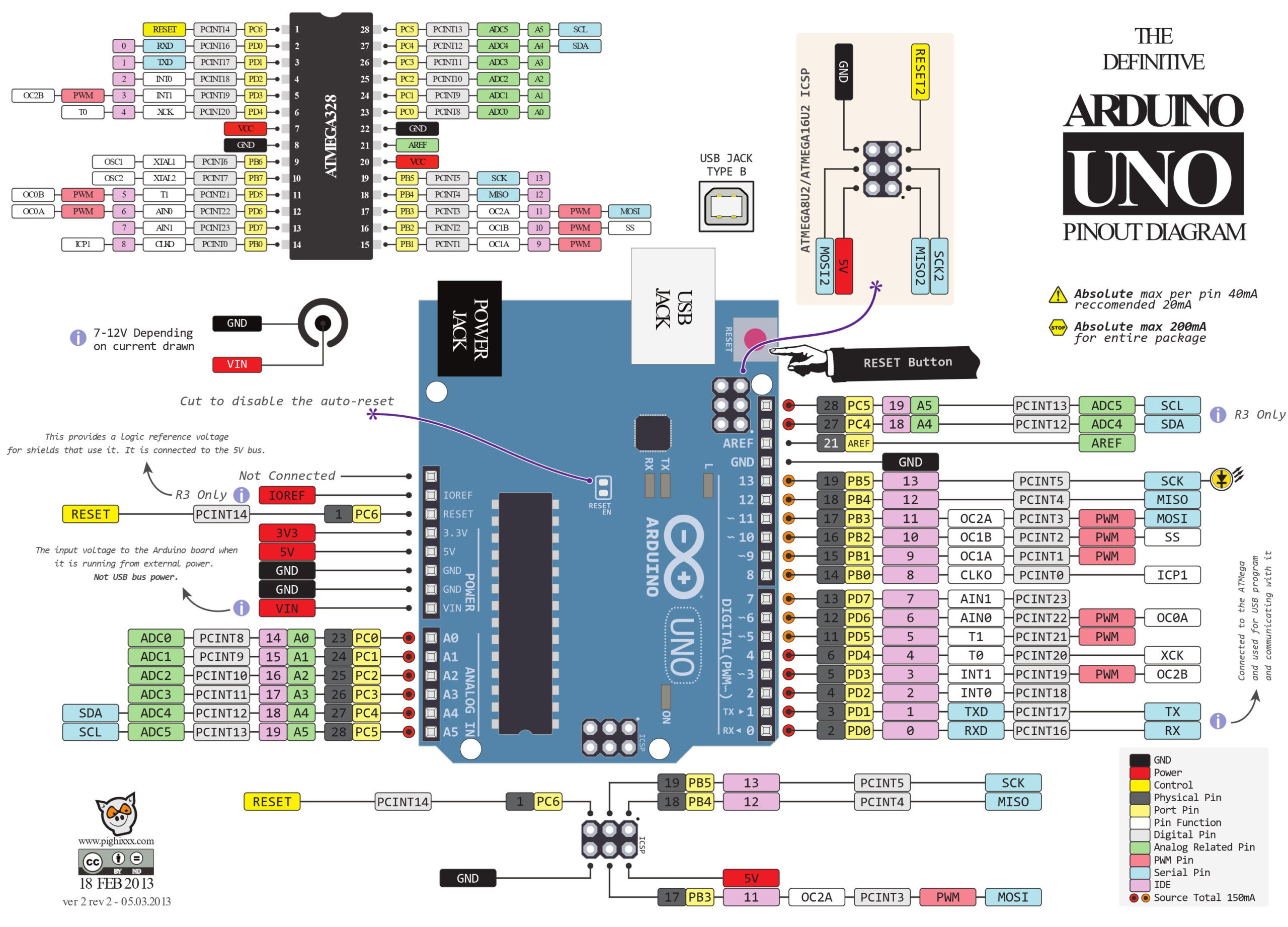
Here is a detailed Arduino UNO Pinout Diagram with colored labels and legends to help you easily identify the functionalities that each pin can perform. It also has the Atmega328p AVR microcontroller pinout diagram to ease the mapping from the Arduino IO numbered pins to the actual microcontroller’s pins.
You can right-click and open in a new tab to view the full-resolution image and/or download it to your computer for reference.
Arduino UNO Pinout – Power Pins
The Arduino UNO board has a couple of LDO voltage regulators that provide regulated DC voltage of +5v and +3.3v to power up the main Arduino (Atmega328p) microcontroller. And you can also use the power pins to power up external modules and sensors that you’d like to use with your Arduino board.
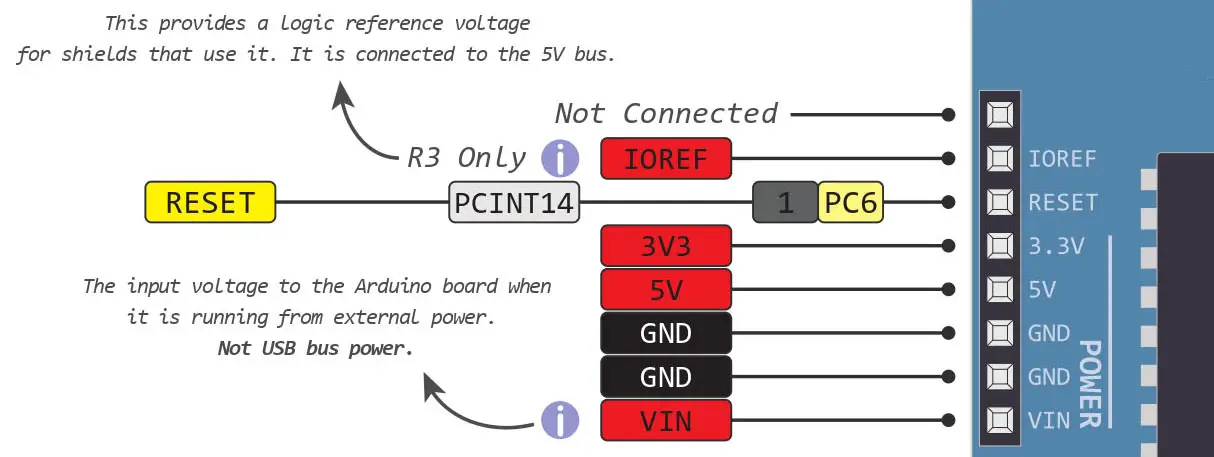
There are multiple options when it comes to powering up your Arduino UNO board that we’ll discuss in detail hereafter in this section. Here is a figure for the power section on your Arduino UNO board with a detailed pinout for each power pin and its functionality.
Arduino Ground Pins
The Arduino UNO board has 3 ground pins that you can use while connecting external devices like LEDs, Sensors, Modules, etc.
Never forget to connect all ground pins of your circuits to the same ground line (always have common ground) as long as those circuits are required to communicate with each other. External sensors and modules not only need the 5v or 3.3v voltage supply, but they also have to have the same ground line shared by the Arduino in order to communicate properly.
+5v Supply
This is a regulated DC voltage output of +5v that you can use to supply external sensors and modules from your Arduino board. Try not to overload it with heavy loads.
+3.3v Supply
This is a regulated DC voltage output of +3.3v that you can use to supply external sensors and modules from your Arduino board. As some sensors and modules are not 5v tolerant, you need to supply them with 3.3v DC and also use a level-shifter with Arduino IO pins as they are also at 5v level.
Arduino VIN Pin
For powering your Arduino UNO board, you have a few options to do so. The first of which is to use the USB cable to provide power to your Arduino board and be able to flash a new firmware to the microcontroller over the USB communication.
Another option is to use the DC jack input to supply the Arduino board with DC voltage (6v-12v) and try not to exceed 9v because higher voltage input will cause the LDO regulators to overheat and potentially get damaged quickly.
The last option is to use the VIN pin to provide an external voltage supply that’s also within the (6v-12v) range exactly like the DC-Jack input. And do not under any circumstances connect multiple power sources at the same time. Use only one option of the 3 we’ve discussed before.
Arduino IOREF Pin
The Arduino IOREF pin provides a 5v logic voltage reference for Arduino Shields that need to use it.
Arduino UNO Pinout – Digital Pins
Arduino GPIO (General-Purpose Input Output) Pins are the digital IO pins of the Arduino UNO board.
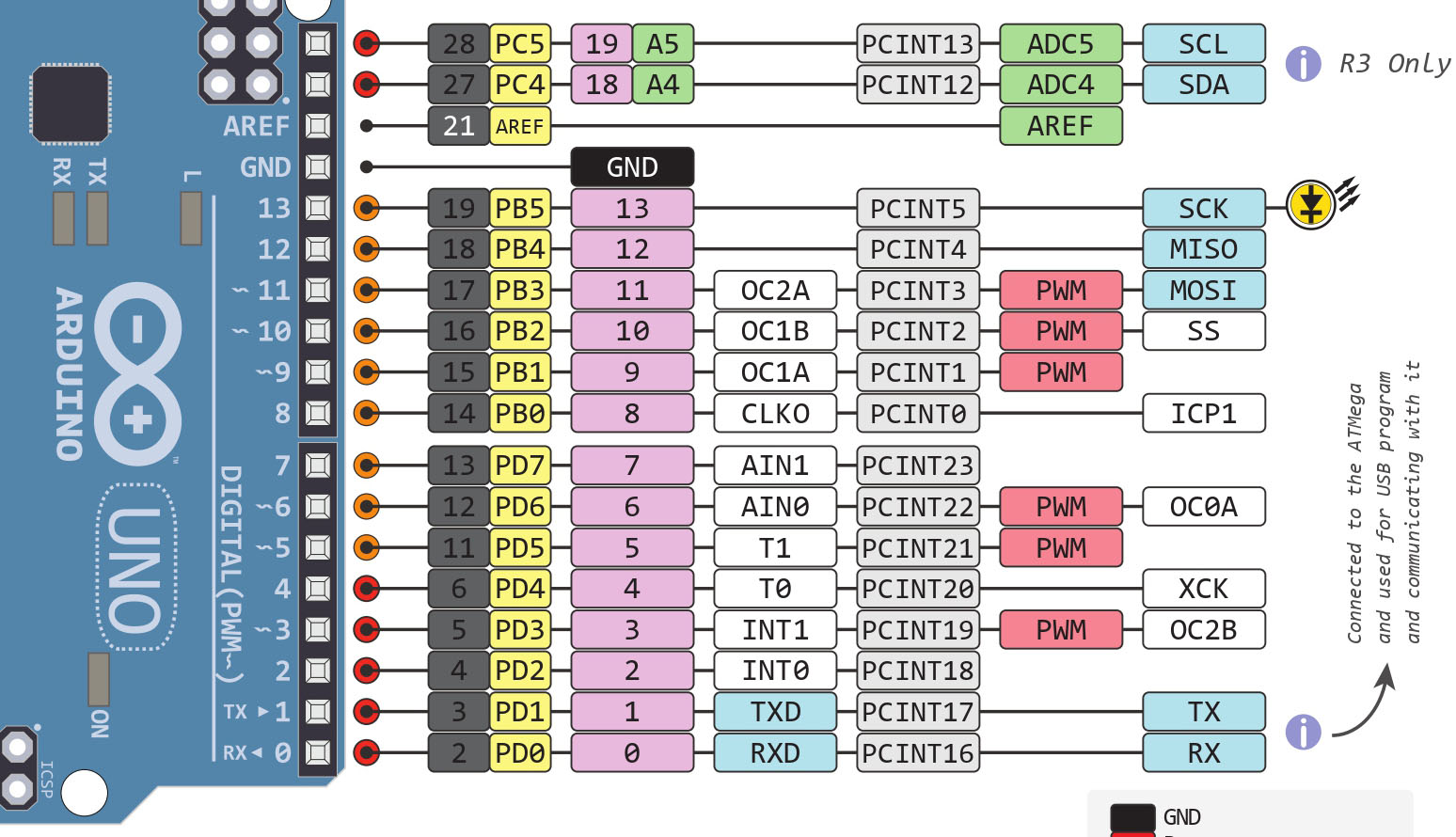
There are 14 GPIO pins on the Arduino UNO board as shown in the figure below.
IO Pins
The pins (0 to 13) are used as a digital input or output for the Arduino UNO board.
Pin 13 is used for the onboard (built-in) LED.
In output mode, the Arduino digital pin is:
- 5v (when the digital pin is set HIGH)
- 0v (when the digital pin is set to LOW).
In input mode, the Arduino digital input pin will read a 0 or 1 depending on the voltage applied to the pin:
- 0v–0.8v: read as 0 (logic 0 or LOW)
- 2v–5v: read as 1 (logic 1 or HIGH)
Any voltage level between 0.8v-2v is considered undefined input for the digital IO pin.
The Arduino’s IO pins are able to source or sink up to 40mA of current per IO pin. This is the maximum absolute current that can be sourced from or sunk to any Arduino’s IO pin at any given time. All Arduino IO pins can source or sink up to 200mA combined at any given time. So make sure you’re not over-driving the IO pins in your application.
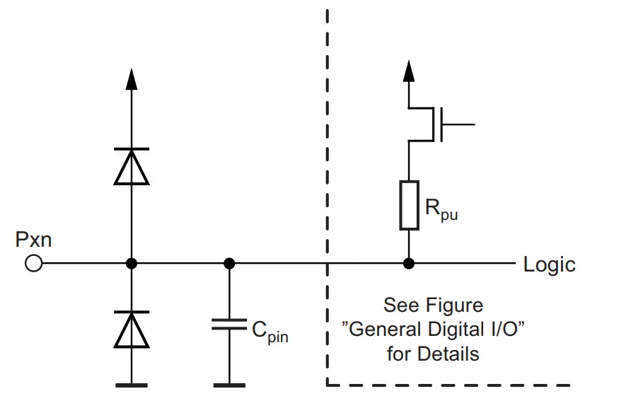
There are two protection diodes for each IO pin that will clip excessive over/under voltage away from damaging any IO pin. However, you still need to be careful with the voltage levels of various components in your system and do level-shifting if needed.
PWM Pins
The pins indicated by the “~” on the Arduino board are the PWM output pins. There are 6 PWM output pins on the Arduino UNO board (pins 3, 5, 6, 9, 10, and 11).
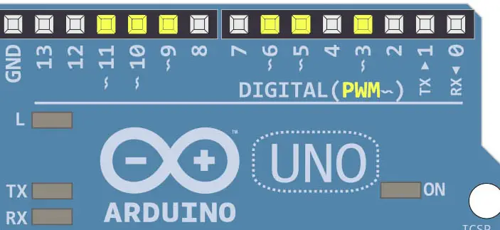
The PWM (Pulse Width Modulation) is a timer mode in which the timer is used to generate a constantly changing digital signal with a specific frequency and duty cycle. PWM is widely used for so many applications like motor control, LED brightness control, and much more.
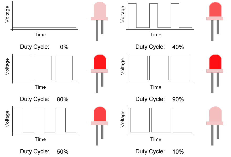
If you need more than 6 PWM outputs for your application, you can either check another board other than Arduino UNO or search for an external PWM controller IC to extend the PWM output pins count. There is also a possibility to create Software PWM (software emulated) output signals but be careful that it’s going to cost you a lot of CPU load.
Check the tutorial below to learn more about Arduino PWM.
This tutorial will provide you with more in-depth information about Arduino PWM output. Starting from the basics of PWM signal, its frequency, duty cycle, and resolution, and will discuss in detail how it works and how to use it in various Arduino control projects.
Interrupt Pins
Interrupt pins are basically digital IO pins that can be configured to be in input mode. And will provide an interrupt signal directly to the CPU whenever the pin state changes. The CPU will pause the current operation and jump to a predefined interrupt handler function and execute it till completion, then it resumes the main loop() function (application).
Interrupt pins can provide a near-immediate response to external events like input pin state change and this can be really useful for different applications that include, but are not limited to, the following list:
- Motor Speed Measurement With Optical Encoder
- Proximity Sensor Interfacing
- Keypad Matrix Scanning
- Ultrasonic Sensor Interfacing
- and much more
There are two types of interrupt pins in the Arduino (Atmega328p) microcontroller: dedicated external interrupt pins and pin-change interrupts.
1. External Interrupts
Those are two dedicated pins INT0 and INT1 that correspond to Arduino IO pins 2, and 3 respectively. Each interrupt pin of those two has its own interrupt vector and can have its unique interrupt handler function.

Note that other Arduino boards may have more dedicated external interrupt pins. The Arduino UNO microcontroller has only 2 dedicated external interrupt pins. And there is no practical way of increasing the dedicated interrupt pins.
2. PCINT (Pin Change Interrupts)
All Arduino UNO digital pins can be used as interrupt pins using the PCINT hardware. This is not a dedicated interrupt signal source unlike the previously discussed external interrupt pints (INT0/INT1).
You can easily notice that every IO pin in the Arduino UNO pinout diagram has a PCINTx label. Where x is the number of the pin change interrupt signal. Those signals are grouped together to generate 3 interrupt signals one for each port of pins (combined together). And the only way to know which pins have their state changed is to manually check for it in your code logic.
Having to manually check which pin state has changed in each port is the major drawback for PCINT interrupts compared to the dedicated external interrupts (INT0/INT1).
Timer/Counter Pin
There are two pins (T0 and T1) that can be used as external clock sources for Timer0 and Timer1 respectively. This can be very useful in a lot of applications depending on the mode of operation for the Timer module. (T0 is Arduino Pin4 and T1 is Arduino Pin5)

In Counter Mode, the T0/T1 pins can be used as an external clock source so you can feed your counter module with external pulses so it keeps counting those incoming pulses. There are several use cases to take advantage of this hardware feature such as:
- Building a Frequency Counter Using Timer Module in Counter Mode
- Measuring Motor Speed Using Optical Encoder + Timer in Counter Mode
- and much more
By counting the incoming pulses count over a fixed time interval, we can determine the frequency (or period) of the input signal. As stated before, this can be very useful for reading sensors like optical encoders, proximity sensors for object counting, and much more.
In Timer Mode, the T0/T1 pins can be used as an external clock source so you can feed your timer module with an external time-base clock generated from any other device (or circuitry) outside of the Arduino (Atmega328) microcontroller itself. One application that you can think of for this hardware feature is the RTC clock (Real-Time Clock).
External RTC crystal (32.768kHz) can feed its output waveform to the T0 or T1 pin which is going to be selected as a clock source. Set the prescaler to 32. And given that Timer0/Timer1 are both 10 bits. Now you’ll get a perfect 1-second timer interrupt that you can use as a time base for your real-time clock application. TOUT = 2n x (Prescaler/FCLK), which turns out to be TOUT = 210 x (32/32768) = 1 second.
ICP (Input Capture) Pins
There is one input capture pin in Arduino UNO (Atmega328p) which is ICP1 that corresponds to Arduino pin 8. This pin is used with the timer module in timer mode while it’s free running. When the ICP pin state changes, the current value of the timer register is captured and saved in the input capture register. It’s also referred to as ICU (Input Capture Unit).

This can be very useful in so many applications that include the following:
- External input signal pulse width measurement
- Motor RPM Measurement With Optical Encoder + ICU
- Ultrasonic Distance Sensor Interfacing With ICU
- Frequency Counter Applications
- POV LED Strip Display
- and much more
ICSP Port Pins
The ICSP (In-Circuit Serial Programming) Header provides an extra way to flash (program) the Atmega328p microcontroller on the Arduino UNO board over the SPI. However, you may rarely need to use it as long as the USB port is functioning properly.

The Arduino bootloader is flashed only once to the microcontroller’s IC and then USB programming is the way to go thereafter. Unless something wrong goes with your chip or if you’ve replaced the Atmega328p microcontroller chip with a brand new one that doesn’t have the bootloader flashed to it. Then the ICSP port will come to the rescue.
Arduino UNO Pinout – Analog Pins
The Arduino UNO has 6 analog input pins labeled from A0 to A5 as shown in the figure below. Those pins can be used with analog peripherals in the Arduino microcontroller such as: ADC (A/D Converter) and the Analog Comparator.
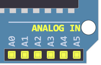
The Analog input pins can also be used as general-purpose digital IO pins as we’ll see hereafter in this section.
ADC (A/D Converter)
The ADC (Analog to Digital Converter) in Arduino is used to read analog voltage input and convert it to its digital representation. Given that the Arduino’s ADC is 10 bits in resolution, the digital output range is therefore from 0 up to 1023. And the analog input range is from 0v up to 5v (which is the analog reference voltage VREF = +5v).
You can use the interactive tool below to set an analog input voltage and see the ADC digital output value that corresponds to the analog input voltage. The output equation for the ADC is as follows: ADC Output = ( Analog input voltage / VREF ) x (2n – 1). Where VREF = 5v and n is the ADC resolution which is 10bits.
If you run out of ADC input pins, you can use an external analog switch (Mux) at the cost of extra digital control pins and a reduced ADC throughput. Using an external dedicated ADC chip is possible and sometimes preferred if your application needs a higher resolution of about 12 or 16 bits.
This is the definitive guide for Arduino ADC. This tutorial will provide you with in-depth information about Arduino ADC, how it works, how to make the best use of it, and a lot of tips and tricks for using ADC to read analog input voltage with Arduino.
Analog Comparator
The analog input pins can be used with the internal Analog comparator in the Arduino’s microcontroller (Atmega328p) instead of the ADC. The analog comparator is really an interesting peripheral and can be a very powerful alternative for the ADC in many applications.
Imagine you need to monitor some input analog voltage and check if it goes below a certain threshold value. You can use the ADC and keep sampling the input pin thousands of times per second and overload the CPU with this hectic task. While you could have used the analog comparator instead and set a threshold to the input voltage, when a voltage drop occurs, the analog comparator will fire an interrupt and the CPU will immediately respond to it. Without overloading the CPU with ADC conversions and polling for the analog input voltage.
There are so many applications where you might need to use the analog comparator which include, but are not limited to, the following:
- Threshold voltage monitoring
- Battery Charging Applications
- ZCD (Zero-Crossing Detection)
- Tachometers
- and much more
We’ll dedicate some future tutorials to discuss Arduino’s internal analog comparator in more detail with example projects as well.
AREF Pin (Analog Reference)
The AREF (Analog Reference) pin can be used to provide an external reference voltage for the analog-to-digital conversion of inputs to the analog pins (A0-A5). The reference voltage essentially specifies the maximum analog input voltage after which the ADC’s output will saturate at 1023.

Let’s recall the ADC’s output equation which is: ADC Output = ( Analog input voltage / VREF ) x (2n – 1). Where the “default” VREF = 5v and n is the ADC resolution which is 10bits.
Using the AREF pin we can change the default VREF voltage and set it to any desired voltage level which allows for more precise A/D conversions. Let’s say we hook up the AREF pin to an external 2.5v DC supply, now we’ll end up having double the resolution of the default 5v analog reference.
Because instead of dividing the 0v-5v range into discrete 1024 digital levels, we’ll now divide the 0v-2.5v range into discrete 1024 digital levels. Which is exactly double the default resolution. But you must make sure that the input analog voltage will not exceed 2.5v after setting the AREF to 2.5v. Otherwise, the ADC will saturate at 1023 if the analog input voltage exceeded the new AREF (2.5v).
Use the interactive tool above to try it yourself and see the effect of lowering the AREF voltage from 5v down to 2.5v and how it increases the ADC resolution by a factor of 2.
| VREF | Analog Input Voltage | ADC Digital Output |
| 5v | 0.01v | 2 |
| 2.5v | 0.01v | 4 |
For the exact same analog input (0.01v), you get more ADC ticks (levels) at VREF=2.5v compared to VREF=5v. Which is what we mean by the resolution is doubled (increased by a factor of 2).
Using Analog Pins As Digital IO
Arduino Uno has a total of 14 digital GPIO pins, out of which 6 pins (from A0 to A5) are analog pins. The question is can we use Arduino analog pins as digital output pins? The answer is YES, and here is how to do it.
First of all, the ADC is a valuable resource in any microcontroller. Under certain circumstances, you’d sacrifice the analog input channels just to get extra digital IO pins. Sometimes an external IO expander would be a better solution instead of sacrificing the ADC analog input channels.
But let’s say you’ve made your decision and you need to have an extra digital pin or two. And the analog input pins are the only hope you’ve got. Here is how you’d go about implementing this.
Just deal with the analog input pins (A0 – A5) as if they’re normal digital IO pins. This means you first need to call the pinMode() function to set the pin mode to OUTPUT. And then call the digitalWrite() function to change the pin state to HIGH or LOW. Check out the tutorial below to get more information about this with a couple of code examples.
This tutorial will give you more in-depth information about Arduino digital IO pins, how to use Analog input pins as digital IO pins, Arduino direct port manipulation, and much more.
Arduino UNO Pinout – Serial Ports Pins
The Arduino UNO’s microcontroller (Atmega328p) has 3 different serial communication ports (protocols). Those ports enable the Arduino to communicate with a huge variety of sensors and modules to extend its functionality and capabilities beyond the limits of the Atmega microcontroller.
Serial communication is a method of data exchange between embedded controllers in the form of bits that are sent/received bit-by-bit in a series. Hence the name, serial communication. There are different hardware ports (protocols) for serial data communication of which (UART, I2C, and SPI) that are supported by the Arduino’s microcontroller.
Each serial communication port (protocol) has its own set of advantages/disadvantages and its best use cases. We’ll dedicate a separate in-depth tutorial for each serial communication protocol of them. But here is a summarized overview of each port and its IO pins.
Arduino UART Pins
UART (Universal Asynchronous Receiver-Transmitter) is the most popular serial communication protocol in embedded microcontrollers. In Arduino, we typically use the UART module for serial communication with the PC via a USB-TTL converter to print serial messages on the serial monitor.
The Arduino UNO has only one UART module which has two pins (RX for receiving serial data and TX for transmitting serial data). The UART pins’ mapping is as follows: RX is Arduino pin 0, and TX is Arduino pin 1 respectively.

Besides serial communication with your PC for debugging and such, the UART is also used for interfacing various sensors and modules such as:
- Bluetooth Module HC-05
- GSM/GPRS Modules
- GPS Modules
- and much more
If you need an extra UART module in your application, you can use the SoftwareSerial library which is a software-emulated UART module. It’ll bit-bang the UART serial pattern on any 2 pins of your choice. But note that it’ll cost you a lot of CPU load and it’s not going to be reliable at high speeds. Because at the end of the day, it’s not a real UART hardware module.
Arduino I2C Pins
I2C or IIC (Inter-Integrated Circuit) is also a very popular serial communication protocol that’s widely used by different sensors and modules in embedded systems. It consists of 2 pins only (one for serial data and one for the serial clock). The Arduino I2C pins are (SDA and SCL).

The I2C is a multi-master multi-slave protocol that supports a large number of devices on the same 2-wire bus. Each device has a unique ID that others can use to directly address that specific device. And it’s considered the most efficient serial communication bus in terms of the number of IO pins needed to establish a communication network of multiple devices.
There are so many modules and sensors that we can interface with Arduino using the I2C bus, which include:
- RTC Clock
- OLED Display Screens
- I2C IO Pins Expander
- External EEPROM Memory Chips
- MPU6050 IMU (Gyro+Accelerometer)
- and much more
Typically, you won’t need more than one I2C module on your Arduino microcontroller. Because if you need to add a new extra device to the I2C bus, it’s as simple as hooking it up to the SCL and SDA lines and you’re good to go. Unlike the UART which is a single master single slave communication port.
The I2C Pins (SDA and SCL) are the Arduino analog input pins A4 and A5 respectively. If you’re going to use the Arduino I2C communication, you’ll not be able to use those 2 pins as analog input channels for the ADC or whatever.
Arduino SPI Pins
SPI (Serial Peripheral Interface) is one of the fastest serial communication ports at all. You can use Arduino’s SPI for communicating with various sensors and modules at much higher data rates compared to the other serial communication protocols.
The SPI communication bus consists of 3 main lines (Serial Data Out, Serial Data In, and Serial Clock). The SPI master device needs also an extra IO pin to select the slave to which it’d like to communicate. This means we need an extra IO pin for each slave device added to the bus which is definitely going to limit the maximum addressable devices on the bus.
The SPI bus lines are named according to a conversion that eases the wiring and usage for users, which goes as follows:
- MOSI (Master Output Slave Input)
- MISO (Master Input Slave Output)
- SCK (Serial Clock)
- SS (Slave Select) “Only Required For SPI Slave Devices”

There are so many applications in which you’d need to use the Arduino SPI bus to interface various sensors and modules which include, but are not limited to, the following examples:
- SPI TFT Display Interfacing
- Dot Matrix Display Interfacing
- External SPI Flash Memory
- External SPI ADC Modules
- nRF24L01 Wireless Modules
- and much more
As stated earlier, We’ll dedicate a separate in-depth tutorial for each serial communication protocol (UART – I2C – SPI). And we’ll create a handful of applications and example projects to practice what we’ll learn.
Arduino UNO Pinout Summary
Those are summarized tables for the Arduino UNO pinout with brief descriptions of each pin’s functionalities.
Arduino Digital IO Pins
| Arduino Pin | Atmega328p Pin | PWM? | Alternative Special Function | Description |
| D0 | PD0 | RX | UART RX Pin | |
| D1 | PD1 | TX | UART TX Pin | |
| D2 | PD2 | INT0 | External Interrupt Pin0 | |
| D3 | PD3 | ✓ | INT1 | External Interrupt Pin1 |
| D4 | PD4 | T0 | Timer0 External Clock Input Pin | |
| D5 | PD5 | ✓ | T1 | Timer1 External Clock Input Pin |
| D6 | PD6 | ✓ | ||
| D7 | PD7 | |||
| D8 | PB0 | ICP1 | Input Capture Unit Pin | |
| D9 | PB1 | ✓ | ||
| D10 | PB2 | ✓ | SS | SPI Slave Select Pin |
| D11 | PB3 | ✓ | MOSI | SPI Master-Out Slave-In |
| D12 | PB4 | MISO | SPI Master-In Slave-Out | |
| D13 | PB5 | SCK | SPI Serial Clock Pin |
Arduino Analog Input Pins
| Arduino Pin | Atmega328p Pin | Alternative Special Function | Description |
| A0 | PC0 | ||
| A1 | PC1 | ||
| A2 | PC2 | ||
| A3 | PC3 | ||
| A4 | PC4 | SDA | I2C Serial Data Line |
| A5 | PC5 | SCL | I2C Serial Clock Line |
| AREF | AREF | AREF | Analog Voltage Reference Input Pin |
Arduino Power Pins
| Pin Name | Description |
| 5v | +5v DC Regulated Supply |
| 3.3v | +3.3v DC Regulated Supply |
| GND | Ground |
| RESET | µC Reset Line |
| VIN | Input DC Voltage (6v-12v). Try not to exceed 9v |
| IOREF | Provides 5v Logic Voltage Reference For Arduino Shields That Use it |
Arduino UNO R3 Schematic Diagram
As an open-source project, the Arduino UNO board schematic design and parts list is completely open-source and available for everyone to download, modify, and create custom Arduino board designs based on it.
You’ll also get a much clear view of the underlying hardware details by carefully studying the Arduino UNO board schematic design files. You can download the Arduino UNO R3 schematic design diagram file using (this link).
Get Started With Arduino UNO Pins
To conclude this tutorial, we’ll highlight the fact that there are so many options for using Arduino pins and a unique set of features that each pin does support. We hope it’s been a helpful guide to helping you decide which Arduino pins to use for your project and what are the fundamental limitations and workarounds for each.
If you’re just getting started with Arduino, you need to check out the Arduino Getting Started [Ultimate Guide] here.
And follow this Arduino Series of Tutorials to learn more about Arduino Programming.
This is the ultimate guide for getting started with Arduino for beginners. It’ll help you learn the Arduino fundamentals for Hardware & Software and understand the basics required to accelerate your learning journey with Arduino Programming.
