In this tutorial, we’ll discuss Arduino Transistor Interfacing To Control Loads Like DC Motors & Power LEDs. You’ll learn how transistors work, and how to interface NPN/PNP transistors with Arduino.
We’ll create an example project to Control The Speed of a DC Motor Using Arduino & TIP120 Transistor, we’ll simulate and run the project code example to test its functionality. Without further ado, let’s get right into it!
Table of Contents
- Arduino Transistor Interfacing
- Arduino NPN Transistor (As Switch)
- Arduino PNP Transistor (As Switch)
- Arduino TIP120 Transistor & 12v Output (Motor Control Example)
- Project Wrap Up
Arduino Transistor Interfacing
The Arduino’s IO pins are able to source or sink up to 40mA of current per IO pin. This is the maximum absolute current that can be sourced from or sunk to any Arduino’s IO pin at any given time. All Arduino IO pins can source or sink up to 200mA combined at any given time.
As a rule of thumb, the Arduino IO pins are not capable of driving any sort of output load devices other than small LEDs, a buzzer, or any tiny device that require a few mA of current to operate. Therefore, we typically use transistors with Arduino as output drivers for high-current load devices (such as Power LEDs, DC Motors, Stepper Motors, etc).
1. Why Use Transistors With Arduino?
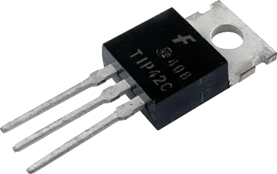
Because the IO pins of the Arduino are not designed to deliver high-current to drive loads like motors or power LEDs. Instead, we use the digital output signal from the Arduino IO pins to trigger a transistor (that works as an electronic switch) to turn ON or OFF the high-current load device (e.g. Motor).
Moreover, the digital output signal that you can get out of Arduino IO pins is (0v to 5v) which is not only insufficient in terms of current delivery capability. But also the output voltage is only 5v which is very low to drive some output devices like 12v relays, DC motors, or 12v LEDs.
For both reasons, high output current delivery capability & high output voltage, we typically use transistors with Arduino to achieve such requirements with ease. We just need to set (bias) the transistor properly to work as a switch (ON/OFF). We’ll discuss how to properly do it hereafter in this tutorial.
2. How Do Transistors Work?
A BJT (Bi-Polar Junction Transistor) can be operated in 3 different regions (modes) by controlling the base voltage (biasing voltage) which we apply to the base pin of the transistors. The IV characteristics curve of a BJT transistor is shown below and it does indicate the 3 operating regions (modes) of a transistor.
- Saturation Region (Switch ON)
- Cut-off Region (Switch OFF)
- Linear Region (Active)
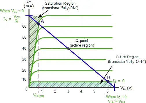
We’re not interested in the linear region (active mode) of the transistor as we’re not going to use it as an amplifier or any other signal generation or processing application. Instead, we’ll be using the transistor as a switch, which means we’ll bias the BJT to operation in either Saturation (ON) or Cut-off (OFF).
3. Transistor Switching ON (Saturation Region)
In this region, the BJT operates as a closed switch, allowing a large current to flow from the collector to the emitter (IC). The transistor is fully turned ON, and the base-emitter & base-collector junctions are forward-biased.
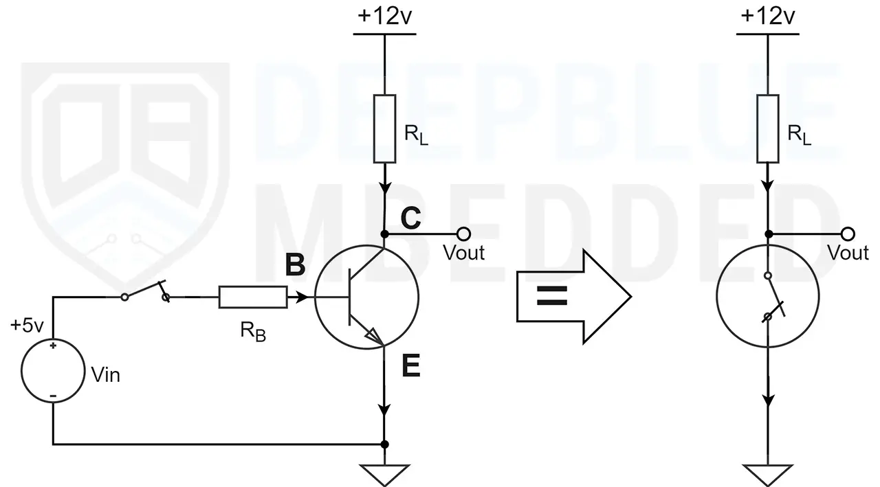
We apply the Vin voltage to the transistor’s base pin using any IO pin of our microcontroller (Arduino), this base voltage will push a small current (IB) through the base of the transistor causing it to go into saturation region (the transistor becomes like a closed switch).
Consequently, the Vout will be equal to the VCEsat of the transistor (around 0.2v) which is nearly zero. Now, the load RL (can be a motor, LED, or whatever) will have a voltage difference across its terminals, and current (IC) will flow through it because the circuit is closed. Your device will turn ON.
4. Transistor Switching OFF (Cut-OFF Region)
In this region, the BJT acts as an open switch, preventing any significant current flow from the collector to the emitter. The transistor is fully turned OFF, and the base-emitter & base-collector junctions are reverse-biased.
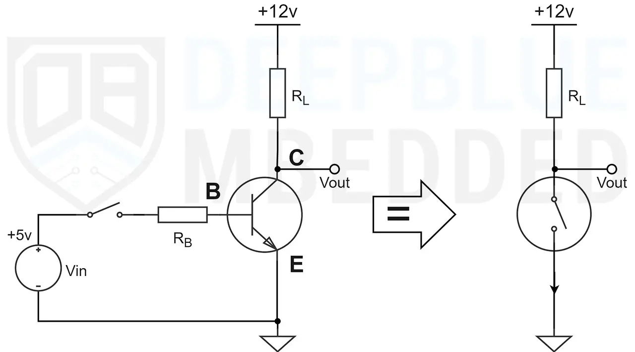
We drive the Vin voltage to the transistor’s base pin to LOW (0v) using any IO pin of our microcontroller (Arduino), this will prevent any current from flowing through the base of the transistor causing it to go into the cut-off region (the transistor will not conduct and becomes like an open switch).
Consequently, the Vout will be equal to the VCC which is the supply voltage of your circuit. Now, the load RL (can be a motor, LED, or whatever) will have no voltage difference across its terminals, and no current will flow through it because the circuit is opened. Your device will turn OFF.
5. Selecting a Transistor For Your Arduino Project
You need to consider the voltage and current requirements of your project. Ensure that the transistor you select can handle the voltage levels and current demands of your load. Look for the maximum collector-emitter voltage (VCE) and collector current (IC) ratings specified in the transistor’s datasheet.
For example, the TIP120 NPN Darlington transistor has an IC maximum rating of 5A according to its datasheet. It can handle up to 8A current spikes for short periods of time. This can be suitable for most LED & motor control applications.
Arduino NPN Transistor (As Switch)
Let’s say you’ll be using an NPN transistor as a switch with your Arduino board to control some random load device (LED, Motor, or Heater). Here’s how to set up your circuit and calculate the required base resistor to bias the transistor so it goes into saturation (fully turn ON) without over-driving the device.
1. NPN Transistor Switching Circuit Diagram
Here is a generic circuit diagram for an Arduino NPN Transistor switch that can be used to control any load (like DC Motor, LED, Heater, etc). The load supply is separated from the Arduino power supply but they share a common ground as you can see in the diagram below.
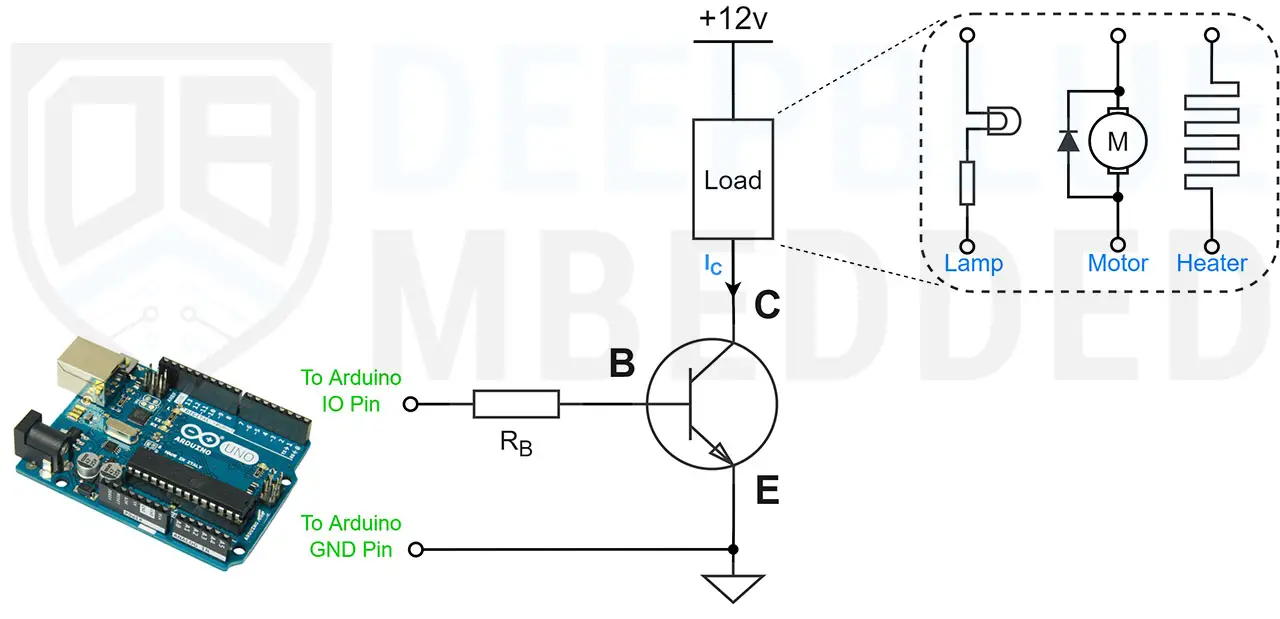
The only part that needs calculation for this design is the base resistor (RB) of the transistor. Which should be chosen properly to drive the transistor into saturation region while avoiding over-driving conditions. We’ll discuss next how to choose the RB resistor’s value according to your project’s requirements.
2. NPN Transistor As Switch Example & Calculations
To better understand the calculations involved in the design process, let’s consider the following example and walk through the calculations step by step.
Let’s say you’d like to drive a DC Motor with your Arduino board and that motor draws around 0.25A in normal operation and can go up to 1A at full load. So you’ve chosen an XYZ transistor that has a DC current gain of (β = 200) and can handle up to 3A of IC current so it’s safe to drive our motor.
We’ll use an Arduino IO output pin (a PWM pin) to drive the transistor’s base, but what should be the value of that RB resistor? Given that the Arduino IO pin voltage = 5v.
1- We should find out the base current required to drive the transistor into saturation at the required output current which is IC = 0.25A
The transistor’s base current (IB = IC / β)

2- Then, we can calculate the base resistance (RB) required to achieve the base current (IB) that we’ve calculated above.

The nearest standard resistor value is 3.3kΩ which is a little bit lower than the calculation and it’s fine because it does guarantee that the transistor is a little bit deeper into the saturation region not at the edge.
Note that the IB equation shown earlier is approximated for simplicity, the DC gain (β) does drift with temperature and IC current variation. There are some real-world parameters that come into designing a transistor-based driver circuit. But the process shown above will set you up and running with most Arduino projects you might think of.
Arduino PNP Transistor (As Switch)
Let’s say you’ll be using a PNP transistor as a switch with your Arduino board to control some random load device (LED, Motor, or Heater). Here’s how to set up your circuit and calculate the required base resistor to bias the transistor so it goes into saturation (fully turn ON) without over-driving the device.
1. PNP Transistor Switching Circuit Diagram
Here is a generic circuit diagram for an Arduino PNP Transistor switch that can be used to control any load (like DC Motor, LED, Heater, etc). The load supply is equal to the Arduino power supply (both are +5v) and they share a common ground as you can see in the diagram below.
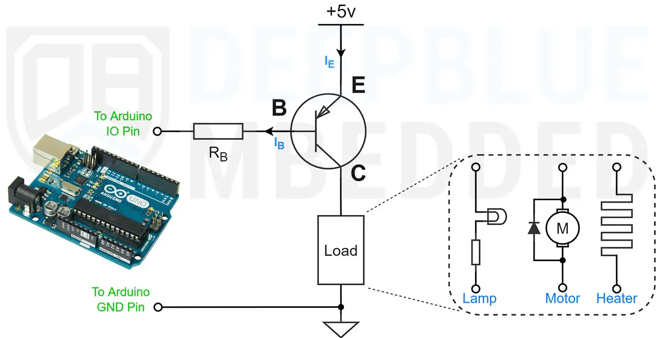
The only part that needs calculation for this design is the base resistor (RB) of the transistor. Which should be chosen properly to drive the transistor into saturation region while avoiding over-driving conditions. We’ll discuss next how to choose the RB resistor’s value according to your project’s requirements.
Note That this circuit diagram will only work provided that you’re going to switch loads at a 5v supply which is the same voltage as the Arduino’s supply as well. However, if you’d like to use a +9v, +12v, or any other high-voltage supply, you’ll need to modify the circuit design a bit more as explained hereafter in this section.
2. PNP Transistor As Switch Example & Calculations
The base resistor (RB) calculation will go exactly in the same way as the NPN transistor that we discussed earlier.
It’s worth noting that the circuit shown above will not work properly if you’ve got a load supply of 9v, 12v, or anything higher than 5v. This is because the Arduino IO pin will not be able to turn OFF the transistor.
The PNP transistor will work in an inverted logic compared to the NPN circuit. The PNP transistor will turn OFF when the Vin of the Arduino IO pin is equal to 5v. If the load’s supply is also 5v, there will be no voltage difference, no current will flow into the base and the transistor will turn OFF.
However, if the load’s supply voltage is let’s say 9v, the Arduino’s IO pin will no longer be able to turn OFF the transistor because the output HIGH (5v) will be lower than the emitter voltage, and the voltage difference will cause current to flow into the transistor’s base and turn it ON. It’ll always be turned ON and can potentially damage either the transistor or the load device.
You may consider using the circuit design below for Arduino PNP transistor interfacing projects that require load supply voltage > 5v.
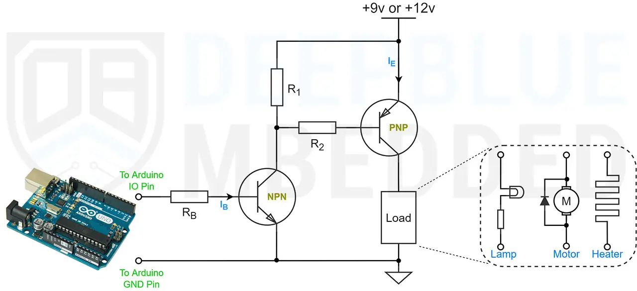
Here we’re using a small NPN pre-driver transistor to drive the PNP output driver transistor. We can easily calculate the RB resistor and control the NPN transistor as we’ve discussed in the previous section.
When the NPN transistor is turned ON, the current will flow through it which in turn causes the PNP transistor to also turn ON. When we turn OFF the NPN transistor, the base voltage on the PNP transistor will equal the supply voltage. No current will flow through the base and the PNP transistor will also turn OFF.
Arduino TIP120 Transistor & 12v Output (Motor Control Example)
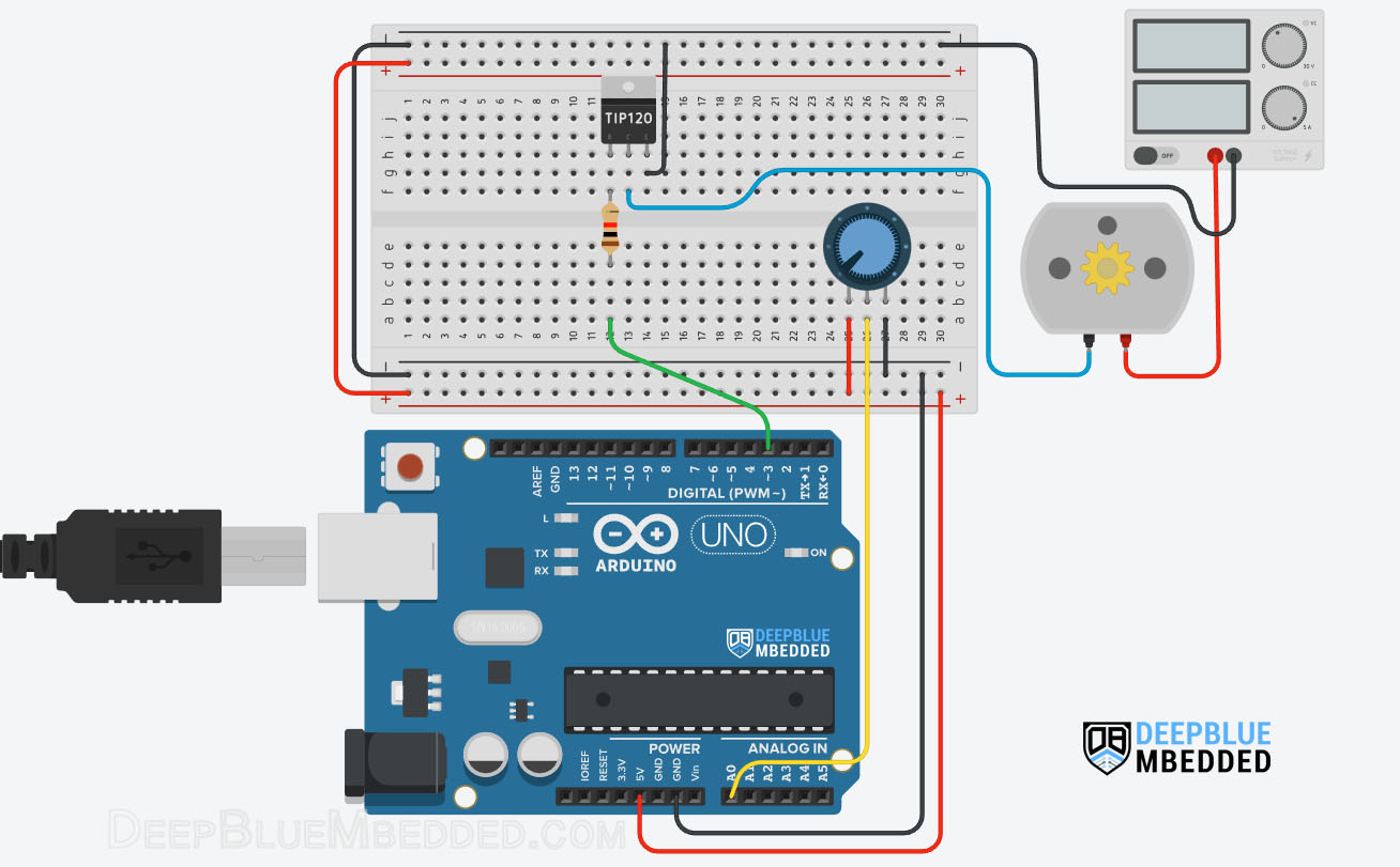
In this example project, we’ll control a DC Motor’s speed with an Arduino PWM output pin + a BJT Transistor. We’ll use a potentiometer and the analogRead() function to get the potentiometer reading and use it to control the PWM’s duty cycle and consequently the motor’s speed.
Arduino boards have several PWM output pins usually. Those pins are designated with a (~) mark next to the pin number on the board. Before discussing how to use the PWM output pins, let’s first define what is the PWM technique and what are the properties of a PWM signal.
Pulse Width Modulation (PWM) is a technique for generating a continuous HIGH/LOW alternating digital signal and programmatically controlling its pulse width and frequency. Certain loads like (LEDs, Motors, etc) will respond to the average voltage of the signal which gets higher as the PWM signal’s pulse width is increased.
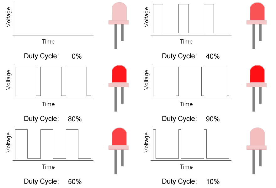
As you can see, the LED gets brighter as the pulse width (duty cycle) increases, and it gets dimmer as the pulse width decreases. And this is typically what we use the PWM output for.
Check the tutorial below to learn more about Arduino PWM. It’s a prerequisite for this project to help you understand the topic in more detail.
This tutorial will provide you with more in-depth information about Arduino PWM output. Starting from the basics of PWM signal, its frequency, duty cycle, and resolution, and will discuss in detail how it works and how to use it in various Arduino control projects.
Wiring
Here is the wiring diagram for this example showing how to connect the BJT Transistor (TIP120) with the DC Motor, Battery, and Arduino PWM output pin. Pay attention to the common ground between the external power source (battery) and the Arduino board.
Example Code
Here is the full code listing for this example.
|
1 2 3 4 5 6 7 8 9 10 11 12 13 14 15 16 |
/* * LAB Name: Arduino PWM DC Motor Speed Control * Author: Khaled Magdy * For More Info Visit: www.DeepBlueMbedded.com */ #define MOTOR_PWM_PIN 3 void setup() { pinMode(MOTOR_PWM_PIN, OUTPUT); } void loop() { analogWrite(MOTOR_PWM_PIN, (analogRead(A0)>>2)); } |
Code Explanation
First of all, we define the IO pin used for the motor speed control output. It has to be a PWM-enabled IO pin (for UNO: 3, 5, 6, 9, 10, or 11).
|
1 |
#define MOTOR_PWM_PIN 3 |
setup()
in the setup() function, we’ll set the pinMode to be output.
|
1 |
pinMode(MOTOR_PWM_PIN, OUTPUT); |
loop()
in the loop() function, we’ll read the analog input pin of the potentiometer (which is 10-Bit resolution) and convert it to 8-Bit resolution by dividing by 4 (or right-shifting twice). Now, we’ve mapped the analog input value to the PWM duty cycle range.
Using Arduino analogWrite() function, we’ll write back the ADC scaled reading as a duty cycle for the PWM to control the speed of the motor accordingly.
|
1 |
analogWrite(MOTOR_PWM_PIN, (analogRead(A0)>>2)); |
Simulation
Here is the simulation result for this project on the TinkerCAD simulator. Don’t pay much attention to the motor rotation animation, it may not be rendered in real-time or it’s spinning really fast so we can’t judge the motor speed or anything other than the DC current drawn from the power supply which correlates with the speed change.
You can check this simulation project on TinkerCAD using this link.
Testing Results
Here is the result of testing this project code example on my Arduino UNO board.
Note That BJT transistors are not ideal for high-power driver applications (like DC Motors, Power LEDs, etc). You’d better off using a MOSFET Transistor With Arduino for high-power driver applications.
Required Parts List
Here is the full components list for all the parts you’d need to perform the practical LABs mentioned in this tutorial and the whole Arduino Programming series of tutorials found here on our website.
* Please, note that those are affiliate links and we’ll receive a small commission on your purchase at no additional cost to you, and it’d definitely support our work.
| QTY. | Component Name | Amazon.com | AliExpress | eBay |
| 1 | TIP120 BJT Transistor | Amazon | AliExpress | eBay |
| 1 | Arduino UNO Kit | Amazon | AliExpress | eBay |
| 1 | Complete Arduino Sensors/Modules Kit | Amazon | AliExpress | eBay |
| 1 | DC Power Supply | Amazon | AliExpress | eBay |
| 1 | BreadBoard | Amazon | AliExpress | eBay |
| 1 | LEDs Kit | Amazon & Amazon | AliExpress | eBay |
| 1 | Resistors Kit | Amazon & Amazon | AliExpress | eBay |
| 1 | Capacitors Kit | Amazon & Amazon | AliExpress & AliExpress | eBay & eBay |
| 1 | Jumper Wires Pack | Amazon & Amazon | AliExpress & AliExpress | eBay & eBay |
| 1 | Push Buttons | Amazon & Amazon | AliExpress | eBay |
| 1 | Potentiometers | Amazon | AliExpress | eBay |
★ Check The Links Below For The Full Course Kit List & LAB Test Equipment Required For Debugging ★
Download Tutorial’s Attachments
You can download all attachment files for this Article/Tutorial (project files, schematics, code, etc..) using the link below. Please consider supporting our work through the various support options listed in the link down below. Every small donation helps to keep this website up and running and ultimately supports the whole community.
Project Wrap Up
To conclude this tutorial, we can say that you can easily use Transistors with Arduino to control various devices (like DC Motors, LEDs, Heaters, Electromagnets, etc). You can create your own driver circuits with NPN/PNP transistors using the information in this tutorial so make sure you get the hang of it because we’ll use it in future tutorials & projects. It’s highly recommended that you check out this Arduino PWM Tutorial as well.
If you’re just getting started with Arduino, you need to check out the Arduino Getting Started [Ultimate Guide] here.
And follow this Arduino Series of Tutorials to learn more about Arduino Programming.
This tutorial will give you more in-depth information about MOSFET transistors with Arduino for driving high-power devices like DC Motors, Power LEDs 3W/10W, and much more.
![Arduino MOSFET Switch N-Channel IRF520 + PWM [Tutorial] Arduino MOSFET Switch N-Channel IRF520 + PWM [Tutorial]](https://deepbluembedded.com/wp-content/uploads/2024/06/Arduino-MOSFET-Switch-N-Channel-IRF520-PWM-Tutorial-300x169.jpg)
