In this tutorial, you’ll learn Arduino Port Manipulation using Arduino registers access. We’ll discuss how Arduino IO pins work at a low level and how DDR, PORT, and PIN registers are used to control the operation of IO ports/pins. Then we’ll test some Arduino port manipulation techniques and assess the speed improvement introduced by doing so.
Finally, I’ll give you some macros that implements all Port operations & single-pin operations that you’d ever need in your projects in order to directly access the IO pins in a safe way with minimal risk of breaking other functionalities. We’ll discuss a lot of code example in this tutorial, so get prepared!
Table of Contents
- Arduino Ports & Pin Mapping
- Arduino DDR & PORT Registers
- Arduino Registers Access
- Arduino Port Manipulation
- Arduino Fast digitalWrite
- Arduino Fast Digital Read
- Wrap Up
Arduino Ports & Pin Mapping
The Arduino UNO is based on the AVR (Atmega328p) microcontroller which has 3 digital IO ports (PORTB, PORTC, and PORTD). Each port has up to 8 pins numbered from 0 to 7. And there are 3 registers to control each digital IO port which we’ll discuss in the next section.
But for now, let’s check the pin mapping between Arduino IO pins and the Atmega328p microcontroller’s ports and pins. The figure below shows you the Arduino UNO Pinout for all digital IO pins and their mapping to the AVR Atmega328p microcontroller.

Here is a summarized table for the pin mapping between the Arduino IO pins and the Atmega328p microcontroller. Note that even the analog input pins can also be used as digital IO pins and they’re mapped to PORTC on the microcontroller.
| PORT Name | Atmega328p Pin | Arduino Pin |
| PORTD | PD0 | D0 |
| PD1 | D1 | |
| PD2 | D2 | |
| PD3 | D3 | |
| PD4 | D4 | |
| PD5 | D5 | |
| PD6 | D6 | |
| PD7 | D7 | |
| PORTB | PB0 | D8 |
| PB1 | D9 | |
| PB2 | D10 | |
| PB3 | D11 | |
| PB4 | D12 | |
| PB5 | D13 | |
| PORTC | PC0 | A0 |
| PC1 | A1 | |
| PC2 | A2 | |
| PC3 | A3 | |
| PC4 | A4 | |
| PC5 | A5 |
Arduino DDR & PORT Registers
Each port on the Atmega328p has 3 registers to control its operation. The DDRx (Data Direction Register) is used to set the port/pin mode (data direction) whether a specific pin is going to be an output or input pin. The PORTx register is used to set (write) the digital output state of the port/pin. And lastly, the PINx register which is the input buffer register that we can use to read the digital status of the port/pin. Where x can be B, C, or D.
We can set all PORTD pins to be output for example by using the DDRD register and writing to the PORTD register any value we want for the IO pins. Alternatively, we can access only one pin of the PORTD at a time while leaving other pins on the port untouched. There are different ways of accessing port pins as we’ll discuss in the next section.
By direct port manipulation in Arduino, you’re risking breaking things up and you’d be losing the portability aspect of the Arduino platform. However, it can provide significantly faster and better overall control over the IO pins on the Arduino’s microcontroller. But all in all, this sort of performance optimization comes at a cost of reduced portability and a higher risk of breaking the software especially when you’re using different libraries by other people.
Here is the hardware block diagram (from the Atmega328p datasheet) that shows you the internal structure and circuitry for 1 IO pin and all the other pins are assumed to have the exact same hardware circuitry. I tried to break it down into 3 sections for each logical functionality to make it less intimidating for those who are not familiar with digital logic circuits. I’ve also added some labels to ease the demonstration in the next sections hereafter.

Now, let’s check how the DDRx, PORTx, and PINx registers are used to manipulate the Arduino ports and pins directly.
Arduino DDR Registers
There are 3 DDR registers in the atmega328p microcontroller, one for each IO port. This means we’ve got the following data direction registers:
- DDRB
- DDRC
- DDRD
The DDR registers are used to set the mode (input or output) for a specific IO pin or a complete port of pins. It does this by enabling or disabling the output latch tri-state (TRIS) logic. Refer to the diagram shown earlier and search for the TRIS logic element which acts like a controlled switch.
If the TRIS is open (DDRx bit = 0), the physical IO pin will be disconnected from the output latch and we can no longer write to it. And this is the definition for a pin being set as input mode.
If the TRIS is closed (DDRx bit = 1), the physical IO pin will be connected to the output latch. Whatever you write to the output latch (1 or 0) will directly appear on the IO pin. Which is the definition of setting an IO pin to be an output pin.
In other words, the DDR registers’ bits are used to control the mode (input or output) for all IO ports/pins in the microcontroller. And this is technically done by controlling the TRIS logic that connects the output latch to the physical IO pin.
If DDRx bit = 1, the output latch is connected and the pin is set in output mode. If DDRx bit = 0, the output latch is disconnected from the physical IO pin, and it becomes an input pin that we can no longer control (write) its state, but we can easily read its state using the PINx registers.
Arduino PORT Registers
The PORTx registers are the output buffers that we use to write to a specific IO pin or a complete port of pins. The PORTx bit will set the value of the corresponding IO pin to 1 or 0. But it has first to be set as an output pin (TRIS is enabled) by setting the corresponding DDRx bit to 1.
Just like DDR registers, there are also 3 PORT registers. One for each IO port, and they’re as follows:
- PORTB
- PORTC
- PORTD
You should be very careful when dealing with the PORT registers because they can easily corrupt the output value on unintended IO pins if not carefully implemented. For example, PORTD has the serial UART signals RX/TX on bits 0 & 1, and the I2C pins are on PORTC bits 4 & 5. Writing to a complete port that has an alternative function enabled can, and will, break it if you were not careful enough.
Arduino PIN Registers
The PIN register is the input buffer register for each port. We can use this register to read the digital state of a single input pin or a whole port at once. As stated earlier, there is a PINx register for each port available on the Atmega328p microcontroller, which means the available PINx registers are as follows:
Each register is considered the input buffer register for the ports (B, C, and D) respectively.
- PINB
- PINC
- PIND
Whether the selected mode for the port/pin by the DDRx register is input or output, the PINx register can be used to get the port/pin state independently of the mode being selected. As shown in the hardware block diagram above, for each IO pin there is a latch preceding the PINx register’s bit.
This forms a synchronizer circuit that suppresses a lot of the noise and prevents metastability if the pin state is flipped near the edge of the internal clock. And it also introduces a 1 system clock delay (at maximum) for the actual pin state to appear at the corresponding PINx register’s bit.
Arduino Registers Access
Let’s say we’d like to set the Arduino pin 10 to be an output pin and directly write to it HIGH and LOW. Here is how to do it by port registers manipulation. First, we need to recall the Arduino-Atmega328p pin mapping diagram that I’ve shown to you near the beginning of this tutorial.
From the pin mapping diagram, we can see that Arduino pin 10 maps to pin PB2 (in PORTB) on the Atmega328p microcontroller. Therefore, to set its mode to be an output pin. We’ll do the following.
DDRB = 0b00000100;
Or we can write it in HEX format like this:
DDRB = 0x04;
Both lines are perfectly the same and do the same function of setting the Arduino pin 10 (PB2) to be an output pin. This is equivalent to the functionality of the pinMode function ( pinMode(10, OUTPUT) ).
Now, in order to control the pin’s digital state, we can use the PORTB register to directly write to the pin HIGH or LOW. Here is how it’s done:
PORTB = 0b00000100;  // Sets The Pin10 (PB2) HIGH
PORTB = 0b00000000;  // Sets The Pin10 (PB2) LOW
And here is the complete example code for toggling an IO pin using direct port registers manipulation and we’ll compare it to the default Arduino builtin digitalWrite() function to assess the speed difference.
void setup() {
  DDRB = 0b00000100;
}

void loop() {
  PORTB = 0b00000100;  // Sets The Pin10 (PB2) HIGH
  PORTB = 0b00000000;  // Sets The Pin10 (PB2) LOW
  delay(1);            // Delay 1ms After Each Pulse
}
And here is the equivalent code example using the pinMode() and digitalWrite() standard functions.
void setup() {
  pinMode(10, OUTPUT);
}

void loop() {
  digitalWrite(10, 1); // Sets The Pin10 (PB2) HIGH
  digitalWrite(10, 0); // Sets The Pin10 (PB2) LOW
  delay(1);            // Delay 1ms After Each Pulse
}
After running the code on my Arduino UNO board, and taking the measurement on my oscilloscope. We can easily tell it’s a huge difference in speed already! it’s around 68ns compared to about 4µs. But as I’ve said earlier it’s coming at a cost as we’ll discuss in more detail hereafter.

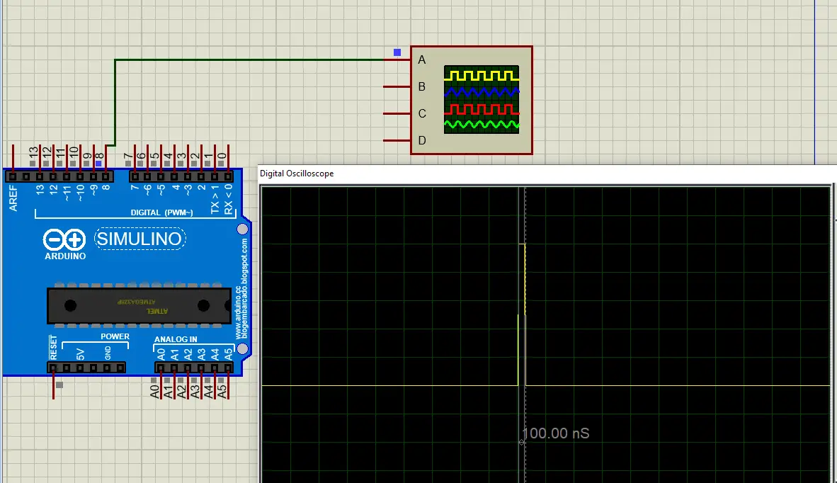
For now, even if you don’t have an oscilloscope at your lab yet, try running both of the examples above in the simulation environment (like Proteus ISIS). And you’ll be getting very similar results as you can see in the screenshot below.

Check out this guide below to help you get started with Simulating your Arduino projects in Proteus (ISIS) simulation environment. This is very helpful if you don’t have an Arduino kit yet or if your lab lacks some test equipment like DSO, function generator, etc.

This article will give more in-depth information about using proteus ISIS for Arduino projects simulation.
Do You Think What We’ve Done is Okay?
Of course not, and here is why!
The issue with this way of register access is that it corrupts all the bits in the whole register even if we only intend to modify only one bit in the register. That’s why it’s not friendly to write to an IO pin using this method. This line of code below is intended to set the PORTB bit2 HIGH.
PORTB = 0b00000100;
Yes, it does set bit2 to be HIGH. But it also forces 0’s to all the other bits in the same port. What if another bit was already 1 before this instruction? well, it’ll get cleared and it’ll have a 0 instead. Which makes this method insufficient to be practically acceptable.
In the next section, we’ll discuss some better techniques in more detail to safely write to an IO pin without risking unintentionally corrupting another pin on the same port.
Arduino Port Manipulation
Now, let’s get to implementing some proper Arduino port manipulation functions. I’ll divide this section into 2 parts, the first one will be dedicated to port operations that can be performed for a whole port of pins. The second section will focus on the single-pin operations that you can perform using direct register access.
We’ll develop some macro (function-like) for each operation to avoid any time wasted in normal function calls. Because, as you should know, the macro definitions are resolved during text replacement by the preprocessor during code compilation. This is going to save a lot of time that would normally be wasted in context switching during function calls and so.
Arduino Port Manipulation Operations
Those are the main operations that you’d need for Arduino port manipulation.
PORT Set Mode
1. All Port Pins Output
We can simply set all the PORTx pins to be output pins using a single instruction as shown below.
#define SET_ALL_OUTPUTS(port) (DDR ## port= 0xFF)
You can call this macro with the name of the DDR register for the port you want to set as output pins, like this:
SET_ALL_OUTPUTS(B);  // Set all pins on port B as output pins
SET_ALL_OUTPUTS(C);  // Set all pins on port C as output pins
SET_ALL_OUTPUTS(D);  // Set all pins on port D as output pins
2. All Port Pins Input
We can simply set all the PORTx pins to be input pins using a single instruction as shown below.
#define SET_ALL_INPUTS(port) (DDR ## port = 0x00)
You can call this macro with the name of the DDR register for the port you want to set as input pins, like this:
SET_ALL_INPUTS(B);  // Set all pins on port B as input pins
SET_ALL_INPUTS(C);  // Set all pins on port C as input pins
SET_ALL_INPUTS(D);  // Set all pins on port D as input pins
3. Set Port Mode
We can set the PORTx pins to be inputs or outputs using the following instruction which writes the desired configuration byte to the corresponding register.
#define SET_PORT_MODE(port, ddr_cfg) (DDR ## port = ddr_cfg)
And here is how to use it to set PORTB pins (0 and 1) as output and pins (2-5) as input.
SET_PORT_MODE(B, 0x03); // Sets Pin 0 and 1 As Outputs. And Pins(2 to 5) As Input
And note that PORTB has only 6 pins (not 8). The Bits number 6 and 7 are not mapped to physical IO pins. Writing to those bits has no effect at all.
PORT Set HIGH
This is a macro to set all the output pins of a specific port to be HIGH.
#define PORT_SET_HIGH(port) (PORT ## port= 0xFF)
And here is how to use it to set all PORTB pins to a HIGH state.
PORT_SET_HIGH(B); // Sets all PORTB pins to a High state
PORT Set LOW
This is a macro to set all the output pins of a specific port to be LOW.
#define PORT_SET_LOW(port) (PORT ## port= 0x00)
And here is how to use it to set all PORTB pins to a LOW state.
PORT_SET_LOW(B); // Sets all PORTB pins to a LOW state
PORT Toggle
This is a macro to toggle (invert) all the output pins of a specific port.
#define PORT_TOGGLE(port) ((PORT ## port) = ~(PORT ## port))
And here is how to use it to toggle all PORTB pins’ states.
PORT_TOGGLE(B); // Toggle all PORTB pins' states
PORT Write
This is a macro to write to all the output pins of a specific port.
#define PORT_WRITE(port, data) (PORT ## port= data)
And here is how to use it to write to all PORTB pins all at once.
PORT_WRITE(B, 0x0F); // Writes to PORTB pins (pin0 to pin3 are HIGH) and (pin4 & pin5 are LOW)
PORT Read
This is a macro to read the state of a whole port.
#define PORT_READ(port) PIN ## port
And here is how to use it to read all PORTB pins all at once.
uint8_t PORTB_State = PORT_READ(B); // Read the state of all PORTB pins
And that’s all possible operations you’d need for Arduino port manipulation. And it’s not very commonly used actually compared to single-pin operations that we’ll move on to next.
Arduino Pin Manipulation Operations
Those are the main operations that you’d need for Arduino single-pin manipulation.
Pin Set Mode
This macro can be used to set a specific pin of a specific port as INPUT or OUTPUT pin.
#define SET_PIN_MODE(port, pin, mode) \
  if (mode == INPUT) { \
    DDR ## port &= ~(1 << pin); \
  } else if (mode == OUTPUT) { \
    DDR ## port |= (1 << pin); \
  }
And here is an example for using it to set Arduino pin13 (PB5) as output pin, and Arduino pin4 (PD4) as input pin.
SET_PIN_MODE(B, 5, OUTPUT);  // Sets Pin13 (B5) As Output Pin
SET_PIN_MODE(D, 4, INPUT);   // Sets Pin4 (D4) As Input Pin
If you don’t like the look of this macro, you can still replace it with the following two instead. I just tried to combine both functions in only one macro.
Alternative 2 macros:
#define SET_PIN_MODE_OUTPUT(port, pin) DDR ## port |= (1 << pin)
#define SET_PIN_MODE_INPUT(port, pin) DDR ## port &= ~(1 << pin)
Pin Set HIGH
This is a macro to set a specific pin in a specific port to be driven HIGH.
#define SET_PIN_HIGH(port, pin) (PORT ## port |= (1 << pin))
And this is how to use it for setting the Arduino pin13 (PB5) to be HIGH.
SET_PIN_HIGH(B, 5); // Sets Pin13 (B5) To Be HIGH
Pin Set LOW
This is a macro to set a specific pin in a specific port to be driven LOW.
#define SET_PIN_LOW(port, pin) ((PORT ## port) &= ~(1 << (pin)))
And this is how to use it for setting the Arduino pin13 (PB5) to be LOW.
SET_PIN_LOW(B, 5); // Sets Pin13 (B5) To Be LOW
Pin Toggle
This is a macro to toggle the output state of a specific pin in a specific port.
#define PIN_TOGGLE(port, pin) (PORT ## port) ^= (1 << (pin))
And this is how to use it to toggle the state of the Arduino pin13 (PB5).
PIN_TOGGLE(B, 5); // Toggle Pin13 (B5) State
Pin Read
This is a macro to read the state of a specific pin in a specific port.
#define PIN_READ(port, pin) (PIN ## port & (1 << pin))
And this is how to use it to toggle the state of the Arduino pin4 (PD4).
uint8_t btnState = PIN_READ(D, 4); // Read The Arduino Pin4 (PD4) Digital State
Arduino Fast digitalWrite
Now, let’s put what we’ve learned so far together and create an example project that implements a fast digitalWrite() alternative to generate fast short pulses output using Arduino port manipulation (register access).
In this example we’ll set Arduino pin8 as an output pin and send to it a HIGH -> LOW pulse, and insert a 1ms time delay after each pulse to easily take the measurements.
Here is the full code example for Arduino Fast digitalWrite.
/*
 * LAB Name: Arduino Fast DigitalWrite
 * Author: Khaled Magdy
 * For More Info Visit: www.DeepBlueMbedded.com
*/
// ---[ Arduino Pin Manipulation Macros ]---
#define SET_PIN_MODE(port, pin, mode) \
  if (mode == INPUT) { \
    DDR ## port &= ~(1 << pin); \
  } else if (mode == OUTPUT) { \
    DDR ## port |= (1 << pin); \
  }
#define SET_PIN_HIGH(port, pin) (PORT ## port |= (1 << pin))
#define SET_PIN_LOW(port, pin) ((PORT ## port) &= ~(1 << (pin)))
//-----------------------------------------

void setup() {
  SET_PIN_MODE(B, 0, OUTPUT);  // Set Pin8 (PB0) As Output
}

void loop() {
  SET_PIN_HIGH(B, 0); // Set Arduino Pin8 (PB0) To HIGH
  SET_PIN_LOW(B, 0);  // Set Arduino Pin8 (PB0) To LOW
  delay(1);           // Delay 1ms After Each Pulse
}
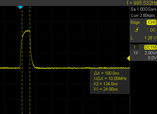
After running this code example on my Arduino UNO board and taking the measurements on my oscilloscope. It turns out to be a 100ns pulse. Which pretty fast pin state update compared to the standard Arduino digitalWrite() function.
Again, if you don’t have an oscilloscope in your lab and still would like to run this experiment, you can use Proteus Arduino Simulation Environment. And you’ll still get very similar results as you can see in the screen shots below. (Both are showing ~100ns pulse)
| Results From Real Arduino UNO & My Siglent Oscilloscope | Results From Protues (ISIS) Arduino Simulation |
 |
 |
However, if you can still remember, we did this same experiment near the beginning of the tutorial and it was much faster (the pulse was around 68ns).
Why is it a little bit slower than the previous example where we did direct port manipulation using the following code?
void setup() {
  DDRB = 0b00000100;
}

void loop() {
  PORTB = 0b00000100;  // Sets The Pin10 (PB2) HIGH
  PORTB = 0b00000000;  // Sets The Pin10 (PB2) LOW
  delay(1);            // Delay 1ms After Each Pulse
}
The reason for this is that the code above (we used in the earlier example) was not portable or friendly in terms of the pin change. It writes a 1 and 0 to a specific bit but it also forces 0’s to all the other bits in the same register wich is going to disrupt all other functionalities on the same port.
The portable macros that we’ve developed later on like the following one, for example, solves this issue but it introduces a little bit of delay.
#define SET_PIN_HIGH(port, pin) (PORT ## port |= (1 << pin))
The reason this macro above takes more time than the direct full register access is that after text replacement by the pre-processor, we’ll end up having (1<<pin) which is a bitwise instruction that needs some processing by the CPU. Which makes up for the ~32ns speed difference between both methods. And it’s definitely worth it for the sake of portability and safe pin state update.
Arduino Fast Digital Read
Similar to the Arduino Fast digitlWrite, we can also implement a fast digital read using the Arduino port manipulation (direct register access) macros that we’ve developed earlier.
Here is an example for implementing an Arduino fast digital read function and using it to read a push button to control an LED output state.
/*
 * LAB Name: Arduino Fast DigitalRead
 * Author: Khaled Magdy
 * For More Info Visit: www.DeepBlueMbedded.com
*/
// ---[ Arduino Pin Manipulation Macros ]---
#define SET_PIN_MODE(port, pin, mode) \
  if (mode == INPUT) { \
    DDR ## port &= ~(1 << pin); \
  } else if (mode == OUTPUT) { \
    DDR ## port |= (1 << pin); \
  }
#define SET_PIN_HIGH(port, pin) (PORT ## port |= (1 << pin))
#define SET_PIN_LOW(port, pin) ((PORT ## port) &= ~(1 << (pin)))
#define PIN_READ(port, pin) (PIN ## port & (1 << pin))
//-----------------------------------------

void setup() {
  SET_PIN_MODE(D, 4, INPUT);   // Set Pin4  (PD4) As Input
  SET_PIN_MODE(B, 5, OUTPUT);  // Set Pin13 (PB5) As Output
}

void loop() {
  while(PIN_READ(D, 4)) // Read Push Button Input Pin
  {
    SET_PIN_HIGH(B, 5); // Set Arduino Pin13 (PB5) To HIGH
  }
  SET_PIN_LOW(B, 5);  // Set Arduino Pin13 (PB5) To LOW
  delay(1);
}
And ofcourse you can do the same testing for speed and compare it to the Arduino digitalRead Speed to assess the improvement in speed by implementing direct Arduino port manipulation.
Parts List
Here is the full components list for all parts that you’d need in order to perform the practical LABs mentioned here in this article and for the whole Arduino Programming series of tutorials found here on DeepBlueMbedded. Please, note that those are affiliate links and we’ll receive a small commission on your purchase at no additional cost to you, and it’d definitely support our work.
Download Attachments
You can download all attachment files for this Article/Tutorial (project files, schematics, code, etc..) using the link below. Please consider supporting my work through the various support options listed in the link down below. Every small donation helps to keep this website up and running and ultimately supports our community.
Wrap Up
To conclude this tutorial, we can say that Arduino port manipulation is a risky business if not cautiously implemented. It does introduce significant speed improvement especially if you’d like to replace a basic operation like digitalWrite or digitalRead inside an ISR handler. Using direct register acces can save a lot of time and CPU load if used in high-frequency ISR handlers or any other critical section in your software.
If you’re just getting started with Arduino, you need to check out the Arduino Getting Started [Ultimate Guide] here.
And follow this Arduino Series of Tutorials to learn more about Arduino Programming.

This is the ultimate guide for getting started with Arduino for beginners. It’ll help you learn the Arduino fundamentals for Hardware & Software and understand the basics required to accelerate your learning journey with Arduino Programming.
FAQ & Answers
Arduino port manipulation is the act of direct register access to control IO ports. For each IO port, there are 3 registers that control its operation (DDRx, PORTx, and PINx), where x can be (B, C, or D).
Using direct register access, we can read or write Arduino pins in a much faster way than using standard digitalWrite and digitalRead functions. It’s a little bit risky if not carefully implemented but can provide a huge boost in speed (if needed).
The Arduino’s AVR (Atmega328p) microcontroller for example has 3 ports, each of which can have up to 8 pins. PORTB has 6 pins, PORTC has 6 pins, and PORTD has 8 pins. Which is a total of 20 GPIO pins. In other words, a port is a group of pins that can have up to 8 pins and those pins are attached to the same IO control registers (DDRx, PORTx, and PINx), where x can be (B, C, or D).
Arduino UNO is based on the AVR Atmgea328p microcontroller. Which has 3 ports (PORTB = 6 pins, PORTC = 6 pins, and PORTD = 8 pins). Which is a total of 20 digital IO pins across the 3 ports.
This tutorial is super helpful! keep up the great work
Glad you’ve found it helpful!
All the best,
Hi