In this tutorial, we’ll learn how to use the Arduino millis() function instead of delay. We’ll discuss how the Arduino millis timer-based function is working and what are the use cases for it. And also the fundamental limitations of the millis() function and how to overcome the millis() overflow (rollover) issue in your Arduino projects. Without further ado, let’s get right into it!
Table of Contents
- Arduino millis() Function
- Arduino millis() vs delay()
- Arduino millis() Delay Example
- millis() Timer Multitasking Example
- Arduino millis() Overflow (Rollover) Issue
- Arduino millis() Reset
- Remarks on millis() Function
- Wrap Up
Arduino millis() Function
The Arduino millis() is a timer-based function that returns to you the time elapsed (in milliseconds) since the Arduino board was powered up. Which can be used to create a time base for various events in your applications (like LED blinking or whatever). All without using the delay() function.
Syntax
|
1 |
millis(); |
Return
The Arduino millis() function returns an unsigned long data type. Which is the time elapsed since the Arduino board was powered up until the millis() function was called.
Example
|
1 |
currentTime = millis(); |
Be advised that the Arduino millis() function is based on a hardware timer interrupt under the hood. Messing up with the hardware timer configurations or disabling the interrupts altogether can and will disrupt the behavior of the millis() function.
Arduino millis() vs delay()
If you’re just getting started with Arduino, it’s always easier to use the delay() function to insert a time interval delay to separate various events. However, it quickly gets messy if you’re dealing with many events and trying to achieve a certain timing behavior. As the delay() function does actually block the CPU and badly affects the responsiveness of your application at the end.
The Arduino millis() function, on the other hand, can be used to get and compare time stamps to achieve different timing requirements as per your application needs. And it has no negative impact on the overall system behavior or responsiveness as we’ll see in this tutorial’s examples hereafter.
This tutorial will provide you with more in-depth information about the Arduino delay() function. How it works and how to use it. And discuss its limitations and alternatives.
Arduino millis() Delay Example
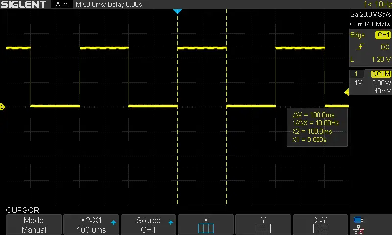
In this example project, we’ll create a time delay using the Arduino millis() function instead of the delay() function. It’s a LED blinking example but it uses the millis() function instead. We’ll toggle the LED once every 100ms.
Code Example
Here is the full code listing for this example.
|
1 2 3 4 5 6 7 8 9 10 11 12 13 14 15 16 17 18 19 20 21 22 |
/* * LAB Name: Arduino millis() delay Example * Author: Khaled Magdy * For More Info Visit: www.DeepBlueMbedded.com */ unsigned long T1 = 0, T2 = 0; uint8_t TimeInterval = 100; void setup() { pinMode(LED_BUILTIN, OUTPUT); } void loop() { T2 = millis(); if( (T2-T1) >= TimeInterval ) { digitalWrite(LED_BUILTIN, !digitalRead(LED_BUILTIN)); T1 = millis(); } } |
Code Explanation
First of all, we’ll need a couple of unsigned long variables to hold the time stamps (T1 & T2) that we’ll use to determine if the desired time interval has yet elapsed or not.
|
1 |
unsigned long T1 = 0, T2 = 0; |
And we’ll also create a variable to hold the desired delay time interval for the LED blinking event.
|
1 |
uint8_t TimeInterval = 100; |
setup()
in the setup() function, we’ll set the pinMode to be output for the built-in LED pin (13).
|
1 |
pinMode(LED_BUILTIN, OUTPUT); |
loop()
in the loop() function, we’ll call the millis() function to take a time stamp that represents the current time for the Arduino board since it was powered up. And we’ll save that in T2 variable. Then, we’ll check the difference between T1 (time zero) and T2 (the current timestamp) and see if it’s equal to or greater than the desired delay time interval ( TimeInterval ).
If the 100ms time interval has elapsed, the if condition will be satisfied and we’ll toggle the LED output pin and save the current time stamp in the T1 variable. And keep repeating forever.
|
1 2 3 4 5 6 |
T2 = millis(); if( (T2-T1) >= TimeInterval ) { digitalWrite(LED_BUILTIN, !digitalRead(LED_BUILTIN)); T1 = millis(); } |
In this way, we’ve achieved the same functionality of a delay without even using a delay that blocks the CPU for no reason and also we’re using an efficient way that’s easily scalable for larger systems as we’ll see in the next project example.
TinkerCAD Simulation
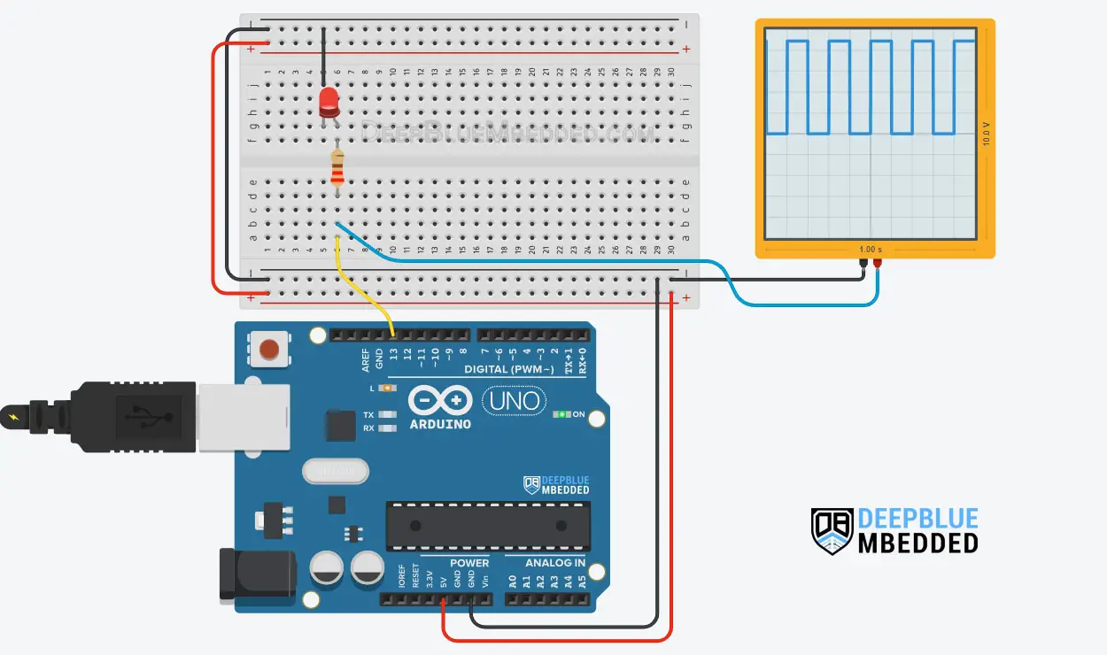
You can check this simulation project on TinkerCAD using this link.
Testing Results
millis() Timer Multitasking Example
We’ll have 3 tasks in this example project, each of which has its own periodicity and a certain logic to execute (task handler function.
- Task 1: executes every 70ms, and it toggles the built-in LED (pin13).
- Task 2: executes every 25ms, reads an input button (pin4), debounces it, and turns ON an LED output (pin5) while the button is pressed.
- Task 3: executes every 200ms, and it sends the button state to the PC over the serial port.
There is no strong reasoning behind choosing those actions for the 3 tasks specifically, I just wanted to demonstrate how to attempt multitasking on Arduino using the millis function.
You can build on top of this example and create a simple small scheduler. This example project is acting more like a simple scheduler’s dispatcher in my opinion.
Code Example
|
1 2 3 4 5 6 7 8 9 10 11 12 13 14 15 16 17 18 19 20 21 22 23 24 25 26 27 28 29 30 31 32 33 34 35 36 37 38 39 40 41 42 43 44 45 46 47 48 49 50 51 52 53 54 55 56 57 58 59 60 61 62 63 64 |
/* * LAB Name: Arduino millis() Multitasking Example * Author: Khaled Magdy * For More Info Visit: www.DeepBlueMbedded.com */ #define BTN_PIN 4 #define LED_PIN 5 unsigned long Task1_T1 = 0, Task2_T1 = 0, Task3_T1 = 0, T2 = 0; uint8_t btnC_State = 1, btnP_State = 1, btnState = 1; uint8_t Task1_Periodicity = 70; uint8_t Task2_Periodicity = 25; uint8_t Task3_Periodicity = 200; void setup() { pinMode(LED_BUILTIN, OUTPUT); pinMode(LED_PIN, OUTPUT); pinMode(BTN_PIN, INPUT_PULLUP); Serial.begin(9600); } void loop() { T2 = millis(); if( (T2 - Task1_T1) >= Task1_Periodicity ) { Task1_Handler(); Task1_T1 = millis(); } if( (T2 - Task2_T1) >= Task2_Periodicity ) { Task2_Handler(); Task2_T1 = millis(); } if( (T2 - Task3_T1) >= Task3_Periodicity ) { Task3_Handler(); Task3_T1 = millis(); } } void Task1_Handler(void) { digitalWrite(LED_BUILTIN, !digitalRead(LED_BUILTIN)); // Toggle LED State } void Task2_Handler(void) { btnC_State = digitalRead(BTN_PIN); if(btnC_State == 0 && btnP_State == 0) { digitalWrite(LED_PIN, 1); } else { digitalWrite(LED_PIN, 0); btnP_State = btnC_State; } } void Task3_Handler(void) { Serial.print("Button State is: "); Serial.println(btnState); } |
Code Explanation
|
1 2 3 4 5 6 7 8 |
#define BTN_PIN 4 #define LED_PIN 5 unsigned long Task1_T1 = 0, Task2_T1 = 0, Task3_T1 = 0, T2 = 0; // Time Stamps uint8_t btnC_State = 1, btnP_State = 1, btnState = 1; // Button State & Debounce uint8_t Task1_Periodicity = 70; // Task 1 Periodicity (Time Interval) uint8_t Task2_Periodicity = 25; // Task 2 Periodicity (Time Interval) uint8_t Task3_Periodicity = 200; // Task 3 Periodicity (Time Interval) |
|
1 2 3 4 |
pinMode(LED_BUILTIN, OUTPUT); pinMode(LED_PIN, OUTPUT); pinMode(BTN_PIN, INPUT_PULLUP); Serial.begin(9600); |
If the task time is due, it’ll get executed and we’ll update its T1 timestamp and keep checking for the other tasks sequentially over and over again.
|
1 2 3 4 5 6 7 8 9 10 11 12 13 14 15 16 |
T2 = millis(); if( (T2 - Task1_T1) >= Task1_Periodicity ) { Task1_Handler(); Task1_T1 = millis(); } if( (T2 - Task2_T1) >= Task2_Periodicity ) { Task2_Handler(); Task2_T1 = millis(); } if( (T2 - Task3_T1) >= Task3_Periodicity ) { Task3_Handler(); Task3_T1 = millis(); } |
Then, we’ll define the Tasks handler functions. This is the core logic to be executed for each task.
Task 1: Toggle the built-in LED output pin (every 70ms).
|
1 2 3 4 |
void Task1_Handler(void) { digitalWrite(LED_BUILTIN, !digitalRead(LED_BUILTIN)); // Toggle LED State } |
Task 2: Reads the input button pin state, and saves it in the current button state variable ( btnC_State), and checks if it’s been the same ( btnP_State) since the last time (debouncing logic). If the button state is confirmed to be LOW, the output LED will be driven HIGH. Otherwise, we’ll drive the LED output LOW.
|
1 2 3 4 5 6 7 8 9 10 11 12 13 |
void Task2_Handler(void) { btnC_State = digitalRead(BTN_PIN); if(btnC_State == 0 && btnP_State == 0) { digitalWrite(LED_PIN, 1); } else { digitalWrite(LED_PIN, 0); btnP_State = btnC_State; } } |
Task 3: Print out the button’s digital state to the serial port (every 200ms).
|
1 2 3 4 5 |
void Task3_Handler(void) { Serial.print("Button State is: "); Serial.println(btnState); } |
TinkerCAD Simulation
Testing Results
Arduino millis() Overflow (Rollover) Issue
When the Arduino mills() internal counter variable reaches its maximum limit (232-1 which is 4,294,967,295) it will overflow and rollover back to zero and start counting up again.
This happens once every 4,294,967,295 ms (49.71 days) and most of your projects won’t be up and running for this long period of time. But after 49.71 days, the counter will overflow and the system will miss at least one action before it corrects itself and goes back to normal.
The behavior at the time of overflow will differ from one project to another depending on the purpose you’re using the millis() function for. Here is the basic millis() delay time interval example we’ll be considering.
|
1 2 3 4 5 6 |
T2 = millis(); if( (T2-T1) >= TimeInterval ) { digitalWrite(LED_BUILTIN, !digitalRead(LED_BUILTIN)); T1 = millis(); } |
Always T2 (the current time stamp) will be larger than T1 (the previous timestamp). And your application will keep running smoothly and toggle the LED every TimeInterval as you’ve programmed it to. Let’s say it’s 100ms
However, at the overflow time, the T1 will have something like (4,294,967,280) and T2 has passed the (4,294,967,295) limit and rolled back to zero and now has a value of 84.
In this case, T2 is no longer larger than T1, and doing the subtraction (T2 – T1) is expected to result in a huge negative number. However, as we’re using unsigned numbers for both variables and the result is also an unsigned number, the subtraction will give the absolute difference between (T2 & T1).
Therefore, there is no need to worry about this issue at all because even when it happens, it won’t disrupt the logical or timing behavior of your system. And you can test this overflow situation on your own without waiting for 50 days by using the code example below. Which recreates the overflow scenario and prints the result that we were afraid it’d be messed up.
|
1 2 3 4 5 6 7 8 9 10 11 12 13 |
unsigned long T1 = 4294967280; // Previous TimeStamp unsigned long T2 = 84; // Current TimeStamp unsigned long T = T2 - T1; // Time Elapsed void setup() { Serial.begin(9600); Serial.println(T); } void loop() { Serial.println(T); delay(100); } |
To stay on the safe side, we can also enforce the type casting for the subtraction result to make sure it doesn’t get messed up if a newer version of the compiler has been released or something. And here is how to do it.
|
1 |
if( (unsigned long)(T2-T1) >= TimeInterval ) |
Arduino millis() Reset
There is no need to do a reset for the Arduino millis() function’s counter. I’ve read online that somebody is trying to reset the hardware timer for millis() in order to prevent the millis() overflow (rollover) issue.
As we’ve stated in the previous section, even when it happens, the millis() overflow (rollover) will not disrupt the timing or logical behavior of your system. And you can explicitly cast the subtraction result to protect your code against this issue.
However, forcing a hard reset to the hardware timer used by the millis() function will mess up a lot of the internal Arduino core functionalities. At the beginning of the list of functionalities that will get disrupted is the PWM which is also dependent on the hardware timer.
Resetting the timer will introduce unwanted glitches in the PWM output channels that correspond to the same hardware time. And it’s not the solution for timer overflow in general.
Remarks on millis() Function
Those are some important notes that you need to know about the Arduino millis() function, so you can use it more efficiently in your projects.
Arduino millis() Max Value
The maximum value for the Arduino millis() function is 232-1 which is 4,294,967,295. This turns out to be 49.71 days before the millis() variable reaches overflow and rollovers back to zero and starts counting up again.
Arduino millis() To Seconds
You can take the millis() function reading and convert it to time in the (hours: minutes: seconds) format. Here is how to take the milliseconds reading and parse out the desired time information.
|
1 2 3 4 |
TimeInMs = millis(); Seconds = TimeInMs / 1000; Minutes = Seconds / 60; Hours = Minutes / 60; |
Arduino millis() Accuracy
The Arduino millis() function is based on a hardware timer interrupt as stated earlier in this tutorial. And the accuracy is around 1 ms as it’s the minimum unit of time this function can return. There is definitely some time wasted in function calls and context switching that will add up to a few microseconds that we won’t feel anyway due to the fact that this function only returns integers not fractions of a millisecond.
Arduino millis() in Interrupt
When using the millis() function, please be aware that it depends on a timer interrupt. If you’ve, for whatever reason, disabled interrupts it won’t work temporarily until you re-enable it back again.
You can also use the millis() function inside ISR (interrupt service routine) handlers. But be advised that it won’t update its reading as long as you’re still in the ISR context. If you’d like to poll the millis() function and wait for some time to pass within an ISR handler, the system will be stuck there forever. Because the millis() function output will not change as long as you’re still in the ISR handler context.
Moreover, using any sort of delay within the ISR handler is an undesirable practice that you should always avoid at any cost. This will introduce a lot of trouble in your system in the long run. Try using the methods introduced in this tutorial to avoid using any sort of “CPU-blocking” delay.
Parts List
Here is the full components list for all parts that you’d need in order to perform the practical LABs mentioned here in this article and for the whole Arduino Programming series of tutorials found here on DeepBlueMbedded. Please, note that those are affiliate links and we’ll receive a small commission on your purchase at no additional cost to you, and it’d definitely support our work.
Download Attachments
You can download all attachment files for this Article/Tutorial (project files, schematics, code, etc..) using the link below. Please consider supporting my work through the various support options listed in the link down below. Every small donation helps to keep this website up and running and ultimately supports our community.
Wrap Up
To conclude this project tutorial, we can say that it’s much better to use the Arduino millis() timer-based function instead of using the delay() function. The millis() overflow (rollover) issue is nothing you need to worry about. And you need to be careful while using millis() or delay() inside ISR handlers.
If you’re just getting started with Arduino, you need to check out the Arduino Getting Started [Ultimate Guide] here.
And follow this Arduino Series of Tutorials to learn more about Arduino Programming.
This is the ultimate guide for getting started with Arduino for beginners. It’ll help you learn the Arduino fundamentals for Hardware & Software and understand the basics required to accelerate your learning journey with Arduino Programming.
FAQ & Answers
The Arduino millis() is a timer-based function that returns to you the time elapsed (in milliseconds) since the Arduino board was powered up. Which can be used to create a time base for various events in your applications (like LED blinking or whatever). All without using the delay() function.
The Arduino millis() function return an unsigned long data type variable.
To use the Arduino millis() timer in your application, do the following steps.
1- call the
millis() function to take a time stamp that represents the current time for the Arduino board since it was powered up. And save that in
T2 variable.
2- Check the difference between
T1 (time zero) and
T2 (the current timestamp) and see if it’s equal to or greater than the desired delay time interval (
TimeInterval ).
3- If the desired time interval has elapsed, the if condition will be satisfied and you’ll do the action you need to do, and save the current time stamp in the
T1 variable. And keep repeating forever.
T2 = millis();
if( (T2-T1) >= TimeInterval )
{
// Do The Action You Want
T1 = millis();
}
You’d be better off using the Arduino mills() function instead of delay() for several reasons. The first of which is the fact that the delay function blocks the CPU unnecessarily which could have been executing some useful logic instead until the desired time passes. For more complex systems, the timing behavior gets really messed up if you’re using delays all over the place.
The Arduino millis() function, on the other hand, can be used to get and compare time stamps to achieve different timing requirements as per your application needs. And it has no negative impact on the overall system behavior or responsiveness.
the Arduino millis() has an accuracy of around 1 ms as it’s the minimum unit of time this function can return. There is definitely some time wasted in function calls and context switching that will add up to a few microseconds that we won’t feel anyway due to the fact that this function only returns integers not fractions of a millisecond.
