In this project tutorial, we’ll display LCD Custom Character With Arduino. We’re going to create some custom LCD character emojis and icons, store them in the LCD’s internal CGRAM, and display those icons (custom special characters) on the LCD screen. In a previous tutorial, we’ve explained in detail the Arduino LCD 16×2 Interfacing which you need to check out first if you need more information about the LCD 16×2 display.
This is going to be a quick project tutorial just to show you the process of LCD custom character generation and display with Arduin and a 16×2 LCD module. Without further ado, let’s get right into it!
There is another version of this tutorial for Arduino I2C LCD 16×2 interfacing & custom character generation that you may need to check out.
Table of Contents
- 16×2 LCD Pinout
- Connecting Arduino to 16×2 LCD (Wiring Diagram)
- Arduino LCD Contrast Adjustment
- LCD Custom Character With Arduino (Generation & Display)
- More Than 8 LCD Custom Characters With Arduino
- Arduino 16×2 LCD Common Issues Troubleshooting
- Arduino LCD Custom Character Wrap Up
16×2 LCD Pinout
This is the pinout for a typical LCD 16×2 display unit. It’s got 8 data lines (you can use only 4 of them or all of the 8). And keep in mind that it needs to be powered from a stable +5v source.

GND is the ground pin.
Vcc is the LCD’s power supply input pin (connects to +5v).
Vo (Contrast Control) is the LCD contrast control pin. We typically use a voltage divider network to establish the control voltage that sets the desired contrast level or simply use a potentiometer to have a controllable contrast level for the LCD display.
RS is the register select pin whose function is to separate the data (text and numbers) from the commands to LCD (like set cursor position, clear LCD display, shift text, etc).
RW is the Read/Write pin. Which determines the type of operation we’ll be doing with the LCD (read or write). As we’re typically using the LCD for displaying output data, it’s rarely set in read mode and this pin is usually held LOW to operate in the WRITE mode.
EN is the enable pin. The enable signal is required for the parallel communication interface of the LCD in order to latch in the incoming data. An enable short pulse is required for the completion of each data transfer operation.
D0-D7 (Data Pins) are the data bus pins (8-bit). The LCD can operate in 4-bit bus mode which means we can send each byte of data in two steps using the 4-bit mode. This will save us 4 IO pins that would have been wasted to create the full 8-pins bus.
LED+ (Anode) is the LCD’s backlight LED’s anode (+) pin. This pin connects to the +5v power supply through a current limiting resistor (220Ω or 330Ω).
LED- (Kathode) is the LCD’s backlight LED’s cathode (-) pin. This pin connects to the ground.
Connecting Arduino to 16×2 LCD (Wiring Diagram)
Here is the wiring diagram for the 16×2 LCD display with Arduino that we’ll be using in all examples hereafter in this tutorial.

And here is a summary table for Arduino -> LCD connections.
| Arduino UNO | 16×2 LCD |
| 2 | D7 |
| 3 | D6 |
| 4 | D5 |
| 5 | D4 |
| 11 | EN |
| 12 | RS |
We’ll be using the 4-bit data mode instead of the 8-bit data mode to same up some IO pins. The LCD is taking up 6 pins already, so we can’t waste 4 more pins just to operate in the 8-bit mode.
Arduino LCD Contrast Adjustment
Before attempting to program the LCD and start actually using it, we need first to test it on a hardware level and also set a proper level of display contrast. This can easily be done after connecting the LCD to Arduino’s +5v power, then using the potentiometer we can set the LCD contrast level as shown in the short demo video below.
If the LCD’s pixels are responding to the potentiometer change, this is a good sign that it should be working and you can proceed further to the Arduino code example projects in the next sections.
LCD Custom Character With Arduino (Generation & Display)
In this example project, we’ll create some custom characters (emojis and icons) and send them to the LCD display. It has an internal CGRAM that can hold up to 8 custom characters at maximum and you’ll learn how to use it in this example project.
The LCD has an internal Character Generator ROM (CGROM). The character generator ROM generates (5×8) dots or (5×10) dot character patterns from 8-bit character codes. It can generate 208 (5×8) dot character patterns and 32 (5×10) dot character patterns. User-defined character patterns are also available by mask-programmed ROM.
Given that the CGROM has 208 character patterns for (5×8) dot displays, this means that not all the 255 ASCII table characters are available by default in the LCD display. You can refer to this tutorial for more information about this. As we’re more interested in the LCD’s internal CGRAM.
In the Character Generator RAM (CGRAM), the user can write new custom character patterns. For (5×8) dots display, eight-character patterns can be written at maximum. Only 8 custom character seems like a small space but it’s what it’s and we’ll see how to use it in this example project.
Arduino LCD Custom Character Generator
You can use this online LCD Custom Character Generator Tool and it’ll give you the Arduino C-Code for it, which you can easily copy and paste into your project code. And here is how to use it:
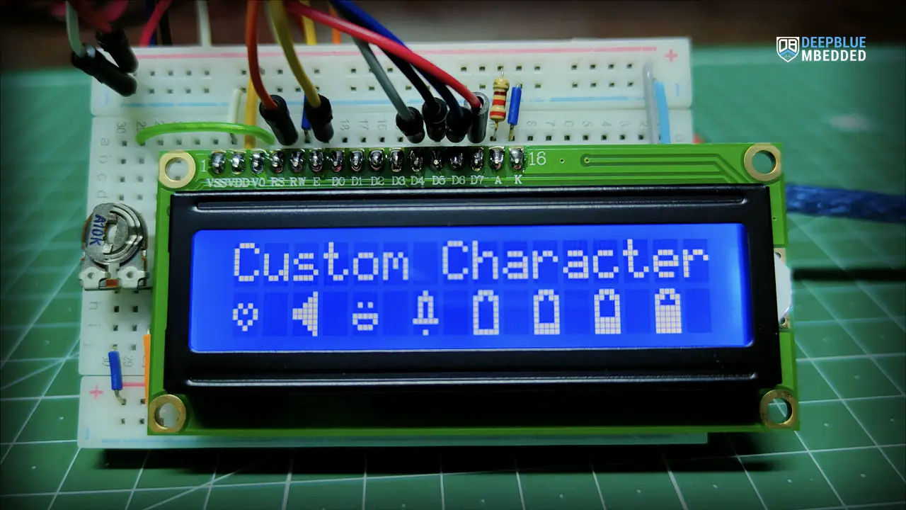
Click on the pixels to draw your custom LCD character, you can invert or clear the entire display cell if you want with the buttons below. If you’re satisfied with how your icon/emoji looks, you can copy the code and you’re good to go. Here are some example custom characters generated by this tool.

I used my custom LCD character generator tool to create the above icons/emojis (heart, speaker, smiley face, notification bell, battery level indicator). We’ll display all of those icons in this example project to show you how it’s done in Arduino code.
Wiring
Exactly the same as the previous example projects.
Example Code
Here is the full code listing for this example.
/*
 * LAB Name: Arduino LCD 16x2 Custom Characters Display
 * Author: Khaled Magdy
 * For More Info Visit: www.DeepBlueMbedded.com
*/
#include <LiquidCrystal.h>

// Create An LCD Object. Signals: [ RS, EN, D4, D5, D6, D7 ]
LiquidCrystal MyLCD(12, 11, 5, 4, 3, 2);
// LCD Custom Characters
uint8_t HeartChar[] = {0x00, 0x00, 0x0a, 0x15, 0x11, 0x0a, 0x04, 0x00};
uint8_t SpeakerChar[] = {0x01, 0x03, 0x07, 0x1f, 0x1f, 0x07, 0x03, 0x01};
uint8_t SmileyFaceChar[] = {0x00, 0x00, 0x0a, 0x00, 0x1f, 0x11, 0x0e, 0x00};
uint8_t BellChar[] = {0x04, 0x0e, 0x0a, 0x0a, 0x0a, 0x1f, 0x00, 0x04};
uint8_t Battery1Char[] = {0x0e, 0x1b, 0x11, 0x11, 0x11, 0x11, 0x11, 0x1f};
uint8_t Battery2Char[] = {0x0e, 0x1b, 0x11, 0x11, 0x11, 0x11, 0x1f, 0x1f};
uint8_t Battery3Char[] = {0x0e, 0x1b, 0x11, 0x11, 0x11, 0x1f, 0x1f, 0x1f};
uint8_t Battery4Char[] = {0x0e, 0x1b, 0x11, 0x1f, 0x1f, 0x1f, 0x1f, 0x1f};

void setup()
{
  // Initialize The LCD. Parameters: [ Columns, Rows ]
  MyLCD.begin(16, 2);
  // Send The Custom Characters To LCD's CGRAM
  MyLCD.createChar(0, HeartChar);
  MyLCD.createChar(1, SpeakerChar);
  MyLCD.createChar(2, SmileyFaceChar);
  MyLCD.createChar(3, BellChar);
  MyLCD.createChar(4, Battery1Char);
  MyLCD.createChar(5, Battery2Char);
  MyLCD.createChar(6, Battery3Char);
  MyLCD.createChar(7, Battery4Char);
  // Clear The LCD Dispaly
  MyLCD.clear();
  MyLCD.print("Custom Characters:");
  // Print The Custom Characters
  MyLCD.setCursor(0, 1);
  MyLCD.write(byte(0));
  MyLCD.setCursor(2, 1);
  MyLCD.write(byte(1));
  MyLCD.setCursor(4, 1);
  MyLCD.write(byte(2));
  MyLCD.setCursor(6, 1);
  MyLCD.write(byte(3));
  MyLCD.setCursor(8, 1);
  MyLCD.write(byte(4));
  MyLCD.setCursor(10, 1);
  MyLCD.write(byte(5));
  MyLCD.setCursor(12, 1);
  MyLCD.write(byte(6));
  MyLCD.setCursor(14, 1);
  MyLCD.write(byte(7));
}

void loop()
{
  // DO NOTHING!
}
Code Explanation
First of all, we need to include the Arduino LiquidCrystal.h library which we’ll be using to control the LCD driver.
#include <LiquidCrystal.h>
Next, we’ll create an object of the LiquidCrystal class and define its parameters. The parameters for the LiquidCrystal object are the pin numbers for the following signals: RS, EN, D4, D5, D5, D7. If you want to add another LCD, you’ll have to create another object with another 6 IO pins for its signals.
LiquidCrystal MyLCD(12, 11, 5, 4, 3, 2); // Creates an LCD object, Parameters: (RS, EN, D4, D5, D6, D7)
We’ll also define the byte array for the 8 custom characters that we’ve previously generated using the online tool.
// LCD Custom Characters
uint8_t HeartChar[] = {0x00, 0x00, 0x0a, 0x15, 0x11, 0x0a, 0x04, 0x00};
uint8_t SpeakerChar[] = {0x01, 0x03, 0x07, 0x1f, 0x1f, 0x07, 0x03, 0x01};
uint8_t SmilyFaceChar[] = {0x00, 0x00, 0x0a, 0x00, 0x1f, 0x11, 0x0e, 0x00};
uint8_t BellChar[] = {0x04, 0x0e, 0x0a, 0x0a, 0x0a, 0x1f, 0x00, 0x04};
uint8_t Battery1Char[] = {0x0e, 0x1b, 0x11, 0x11, 0x11, 0x11, 0x11, 0x1f};
uint8_t Battery2Char[] = {0x0e, 0x1b, 0x11, 0x11, 0x11, 0x11, 0x1f, 0x1f};
uint8_t Battery3Char[] = {0x0e, 0x1b, 0x11, 0x11, 0x11, 0x1f, 0x1f, 0x1f};
uint8_t Battery4Char[] = {0x0e, 0x1b, 0x11, 0x1f, 0x1f, 0x1f, 0x1f, 0x1f};
setup()
in the setup() function, we initialize the LCD object ( MyLCD) using the .begin() function.
MyLCD.begin(16, 2); // Set up the number of columns and rows on the LCD.
Then, we send the 8 custom characters byte-arrays to the LCD to be stored in its CGRAM memory.
// Send The Custom Characters To LCD's CGRAM
MyLCD.createChar(0, HeartChar);
MyLCD.createChar(1, SpeakerChar);
MyLCD.createChar(2, SmilyFaceChar);
MyLCD.createChar(3, BellChar);
MyLCD.createChar(4, Battery1Char);
MyLCD.createChar(5, Battery2Char);
MyLCD.createChar(6, Battery3Char);
MyLCD.createChar(7, Battery4Char);
Next, we’ll clear the entire LCD display screen before writing. This step also moves the cursor to the home position (0, 0).
MyLCD.clear();
And finally, we’ll print the LCD custom characters. This is not a usual print command, it’s a command for the LCD to print the custom character saved in a specific location in the CGRAM memory. The following line of code tells the LCD to print the custom character saved in the CGRAM address location 0.
MyLCD.write(byte(0));
And similarly, we’ll do the same for the rest of the custom characters saved in the CGRAM address location 0 up to 7.
loop()
in the loop() function, nothing needs to be done.
Simulation
Here is the simulation result for this project on the TinkerCAD simulator.

You can check this simulation project on TinkerCAD using this link.
Testing Results
Here is the result of testing this project code example on my Arduino UNO board.

More Than 8 LCD Custom Characters With Arduino
A common question that I’ve received a lot is “Can I display more than 8 custom characters on the 16×2 LCD?”. The short answer is YES. But it’s a little bit tricky to implement. And here is why!
The LCD’s driver chip (Hitachi HD44780) has a hardware limitation for the custom characters that can be stored in the CGRAM at the same time. This is only 8 characters and we can’t change this fact.
However, if your custom characters don’t need to exist in the CGRAM all of the 8 at the same time, we can change the bit pattern of one stored character and replace it with a new one (overwrite it essentially) and print this new character using the same index location of the old character.
The tricky part of this method is to implement a technique to keep track of what the last bit pattern written was. But it’s doable and it’s the only way to work around this fundamental hardware limitation of the HD44780 LCD driver.
You can refer to the Hitachi HD44780 LCD Driver’s Datasheet, and specifically check the CGRAM section (page 13).
Arduino 16×2 LCD Common Issues Troubleshooting
In this section, we’ll discuss some of the most common Arduino 16×2 LCD interfacing issues and how to troubleshoot those issues if you’re facing any of them in your project.
Garbage Characters Display
If your LCD is displaying garbage characters, it’s a strong indicator that there is an issue with data communication between your Arduino board and the LCD module itself. Make sure your connections are correct and the pin numbers for wiring are matching the software configurations that you’ve set in code like this.
LiquidCrystal MyLCD(12, 11, 5, 4, 3, 2); // Creates an LCD object, Parameters: (RS, EN, D4, D5, D6, D7)
LCD Showing Black Boxes or Blank Display
This can be a contrast issue at the Vo pin, so make sure you’re connecting the contrast control potentiometer and turn it to the right and left until it’s properly set to an acceptable level.
Contrast is Ok, But Still Blank Display
This can be a power supply issue, make sure you’re connected to a stable +5v power supply. Sometimes powering from a USB port in a computer can cause power issues like this, so try using a power bank or a proper power supply and check if the issue is still persistent.
Using a poor power supply USB port, poor quality USB cables or even USB extender cables can cause all sorts of power issues. And the LCD display module is sensitive to such issues that you’d not detect during LEDs and buttons example projects.
Parts List
Here is the full components list for all parts that you’d need in order to perform the practical LABs mentioned here in this article and for the whole Arduino Programming series of tutorials found here on DeepBlueMbedded. Please, note that those are affiliate links and we’ll receive a small commission on your purchase at no additional cost to you, and it’d definitely support our work.
Download Attachments
You can download all attachment files for this Article/Tutorial (project files, schematics, code, etc..) using the link below. Please consider supporting my work through the various support options listed in the link down below. Every small donation helps to keep this website up and running and ultimately supports our community.
Arduino LCD Custom Character Wrap Up
To conclude this project, we can say that it’s pretty much easy to create your own custom characters and symbols using this online Custom LCD Character Generator Tool and to display them on the LCD with Arduino code. As long as you need up to 8 custom characters, it’s going to be an easy task. It only becomes tricky when you need more than 8 characters. This is still achievable but requires a little bit of juggling between the CGRAM memory locations to work around the hardware size limit.
If you’re just starting with Arduino, check out the Arduino Getting Started [Ultimate Guide] here.
And follow this Arduino Series of Tutorials to learn more about Arduino Programming.

This tutorial will provide you with more in-depth information about the LCD 16×2 module and how it works, interfacing with Arduino, LiquidCrystal library, and much more. You definitely need to check it out if you didn’t.

This is the ultimate guide for Arduino I2C LCD interfacing. Check it out to learn how the I2C LCD module works, how to use the LiquidCrystal_I2C library function to control it, change the I2C device address, connect multiple LCDs with Arduino using only 2 pins, and much more.
FAQ & Answers
You first need to generate the bit pattern for the desired custom characters that you need. Any online tool can be sufficient for this task (like this tool). After getting the bit pattern for your custom character. You need to send it to the LCD’s CGRAM memory using the lcd.createChar() function. Now, it’s stored in the LCD’s internal CGRAM memory. You can easily print it by sending its index alongside this lcd.write(byte(x)) command to the LCD.
To display custom characters on an LCD with Arduino, you’ll need to perform the following steps:
1- Use an online tool to generate a bit pattern for the desired custom character.
2- Send the bit pattern to the LCD’s CGRAM memory using the lcd.createChar() function. This stores the custom character in the LCD’s internal CGRAM memory.
3- Print the custom character on the LCD by using its index with the lcd.write(byte(x)) command.
You first need to generate the bit pattern for the desired custom characters that you need. Any online tool can be sufficient for this task (like this tool). After getting the bit pattern for your custom character. You need to send it to the LCD’s CGRAM memory using the lcd.createChar() function. Once it’s sent, you can easily print it on the LCD display.