In this tutorial, we’ll discuss Execution Time Measurement With Arduino and how to measure a function or ISR handler execution time in your Arduino projects. We’ll explore 3 different techniques for execution time measurement with Arduino in this guide tutorial.
We’ll create a test setup and code example for each technique we’ll discuss today, we’ll run the measurement process for each technique on a testbench function, and we’ll finally compare the results to draw some conclusions. Without further ado, let’s get right into it!
Table of Contents
- Execution Time For Functions & ISR Handlers
- Arduino Execution Time Measurement – IO Pin
- Arduino Execution Time Measurement – Micros()
- Arduino Execution Time Measurement – Timer
- Benchmark Function & Test Results Comparison
- Wrap Up
Execution Time For Functions & ISR Handlers
For periodic tasks, interrupts handlers (ISRs), or any other function, it’s very critical to have a measurement of how long it takes the CPU to run through till completion. We should have an estimate for how long a task takes to execute especially if it’s periodically executed by the CPU.
We just can’t expect a 10ms periodic function to take more than 10ms to execute. This violates the timing requirement of the periodic function and also means the CPU load is 100% which is one way to define a system failure.
In this tutorial, I’ll show you 3 different techniques that you can use to assess (measure) the execution time for any function, ISR handler, or task in your Arduino projects.
The Execution Time of a function is the time it takes the CPU to run the instructions inside this function from start to completion. Without getting interrupted (preempted).
Enabled interrupts can and will “randomly” preempt the function execution causing it to “apparently” take longer to execute which disrupts the measurement results. Therefore, we need to make sure that global interrupts are disabled before the execution time measurement is started and re-enable interrupts after the measurement completion.
ISR handlers’ execution time, on the other hand, can be easily measured without worrying about such an issue unless interrupts nesting is enabled. Which shouldn’t be enabled in most systems. Refer to this article to learn more about interrupt nesting & why it should always be disabled.
While measuring the execution time of any function, you must make sure interrupts are disabled so it doesn’t disrupt the results of our measurement.
Arduino Execution Time Measurement – IO Pin
In this execution time measurement technique, we’ll be using a GPIO pin and direct register access to accelerate the GPIO pin control. At the beginning of the to-be-measured function, we’ll drive this IO pin to HIGH, and at the end of the function, we’ll drive the IO pin to LOW. We’ll use an oscilloscope to take this measurement manually.
Example Code
Here is the full code listing for the Arduino Function Execution Time Measurement With IO pin.
|
1 2 3 4 5 6 7 8 9 10 11 12 13 14 15 16 17 18 19 20 21 22 23 24 25 26 27 28 29 30 31 32 33 34 35 |
/* * LAB Name: Arduino Execution Time Measurement (IO) * Author: Khaled Magdy * For More Info Visit: www.DeepBlueMbedded.com */ // ---[ Arduino Pin Manipulation Macros ]--- #define SET_PIN_HIGH(port, pin) (PORT ## port |= (1 << pin)) #define SET_PIN_LOW(port, pin) ((PORT ## port) &= ~(1 << (pin))) #define LOOPS 1 float x=1.2345, y=6.789; void TestFunction(void) { cli(); // Disable Interrupts SET_PIN_HIGH(B, 0); // Set IO TestPin //----[ Function Body]---- for(int i=0; i<LOOPS; i++) { x *= y; } //------------------------ SET_PIN_LOW(B, 0); // Clear IO TestPin sei(); // Re-Enable Interrupts } void setup() { pinMode(8, OUTPUT); // Set Pin8 (PB0) As Output } void loop() { TestFunction(); delay(100); } |
Code Explanation
TestFunction()
This is the to-be-measured function. As you know, we should disable the global interrupts at the beginning and re-enable them at the end of the function using the Arduino sei() & cli() functions.
Before the main logic (body) of the function, we’ll drive the test IO pin to HIGH. And we’ll drive the pin back to LOW after the main logic is fully executed.
|
1 2 3 4 5 6 7 8 9 10 11 12 13 |
void TestFunction(void) { cli(); // Disable Interrupts SET_PIN_HIGH(B, 0); // Set IO TestPin //----[ Function Body]---- for(int i=0; i<LOOPS; i++) { x *= y; } //------------------------ SET_PIN_LOW(B, 0); // Clear IO TestPin sei(); // Re-Enable Interrupts } |
setup()
in the setup() function, we just need to initialize the IO test pin to be output.
|
1 |
pinMode(8, OUTPUT); // Set Pin8 (PB0) As Output |
loop()
in the loop() function, we just call the TestFunction() periodically each 100ms.
|
1 2 |
TestFunction(); delay(100); |
Note that in this example, I’m using direct port manipulation for ultra-fast pin access to eliminate the effect of the digitalWrite() function’s execution time on the measurement I’m performing. To learn more about this topic, and you should, it’s highly recommended to check out the tutorial below.
This article will give more in-depth information about Arduino direct port manipulation and register access to control IO pin extremely faster than the default digitalRead & digitalWrite functions.
Proteus (ISIS) Simulation
Proteus (ISIS) is an extremely powerful simulation environment for Arduino with the Arduino add-on library. It can definitely run our test projects for this tutorial. But you won’t feel its power until you need some virtual test equipment like an oscilloscope, function generator, power supply, and advanced SPICE simulation for auxiliary electronic circuitry that you may build around an Arduino microcontroller.
Here is the Arduino project simulation result from the Proteus environment.
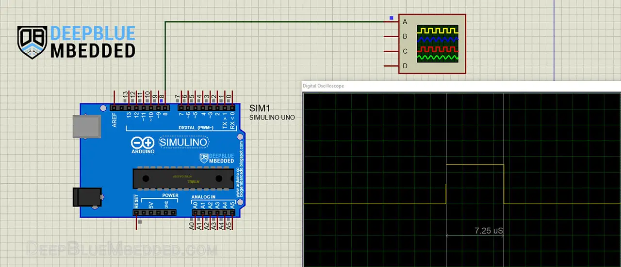
Testing Results
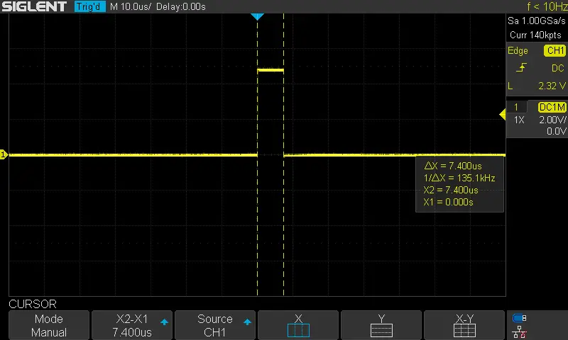
Simulation results are amazingly so close to the real measurement on a real Arduino board with a real oscilloscope. You definitely need to check out the tutorial below to help you get started with simulating your Arduino projects in the Proteus simulation environment.
This article will provide you with more in-depth information about using proteus ISIS for Arduino projects simulation.
Arduino Execution Time Measurement – Micros()
Another technique that can also be used to measure the execution time of functions with Arduino is by utilizing the micros() function to get time stamps at the beginning and end of the to-be-measured function.
The issue with this method is that we just can’t disable interrupts because the micros() function depends on timer interrupts to keep track of elapsed time. Hence, the measurement will be prone to random errors due to active interrupts. But this technique can be effective if you don’t have enabled interrupts in your system.
The upside of this technique is that it’s automatic and doesn’t require user intervention at all. Unlink the IO pin & oscilloscope measurement that we’ve seen earlier. The error can, however, be minimized by taking so many readings & average them over a relatively long time interval.
Example Code
Here is an Arduino example code that implements this measurement technique.
|
1 2 3 4 5 6 7 8 9 10 11 12 13 14 15 16 17 18 19 20 21 22 23 24 25 26 27 28 29 30 31 32 |
/* * LAB Name: Arduino Execution Time Measurement (Micros) * Author: Khaled Magdy * For More Info Visit: www.DeepBlueMbedded.com */ #define LOOPS 1 float x=1.2345, y=6.789; unsigned long T1 = 0, T2 = 0; void TestFunction(void) { T1 = micros(); //----[ Function Body]---- for(int i=0; i<LOOPS; i++) { x *= y; } //------------------------ T2 = micros(); } void setup() { Serial.begin(115200); } void loop() { TestFunction(); Serial.println(T2-T1); delay(10); } |
Code Explanation
As you might have noticed in the example code above, I’ve taken two time stamps inside the TestFunction, T1 at the beginning and T2 at the end. The measured execution time is therefore = (T2-T1) μs.
Simulation Results
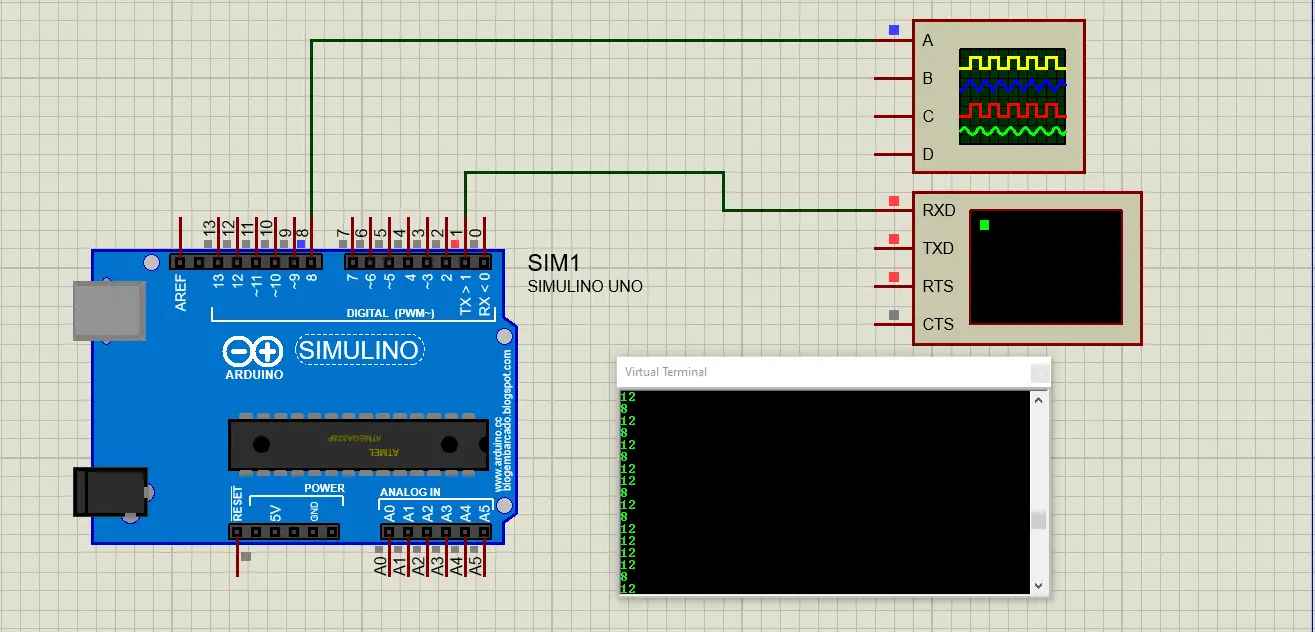
Testing Results
Here is the result of running this function execution time measurement code example on my Arduino UNO board.
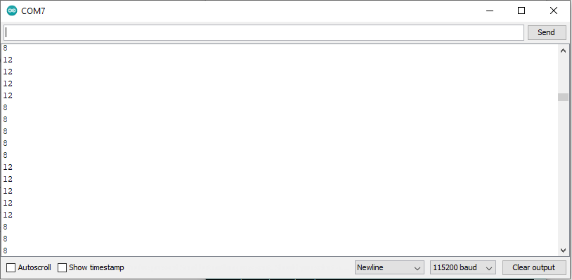
This means the TestFunction takes “on average” around 10μs to run with (LOOPs = 1). Which shows us that this technique has a lower resolution compared to the previous IO pin method.
The micros() function has a resolution of 4μs because it only returns a number that’s a multiple of 4. So keep this in mind and don’t assume it’ll give you a result that’s more accurate than this.
You can increase the number of LOOPs that the function should execute to prolong its execution time, this will therefore reduce the effect of micros() resolution on the measurement result.
Arduino Execution Time Measurement – Timer
Another technique that I use quite often because it’s completely automatic and you can do it hands-free, no oscilloscope manual measurement is required or whatsoever. It depends on a Hardware Timer.
We’ll set up Timer1 to be free-running @ maximum speed (prescaler=1). And we’ll read the Timer1 counter register (TNCT1) at the beginning and end of the to-be-measured function. The absolute difference between two time stamps is therefore the execution time measurement.
We can leave interrupts enabled if we need need to keep track of timer overflow interrupts. You can however, use a larger prescaler to guarantee that no overflow will occur and disable interrupts to eliminate its effect on the measurement results.
Example Code
Here is an Arduino example code that implements this measurement technique.
|
1 2 3 4 5 6 7 8 9 10 11 12 13 14 15 16 17 18 19 20 21 22 23 24 25 26 27 28 29 30 31 32 33 34 35 36 37 38 39 40 41 42 43 44 45 |
/* * LAB Name: Arduino Execution Time Measurement (Timer) * Author: Khaled Magdy * For More Info Visit: www.DeepBlueMbedded.com */ #define LOOPS 1 float x=1.2345, y=6.789; int T = 0, T1 = 0, T2 = 0; void TestFunction(void) { cli(); T1 = TCNT1; //----[ Function Body]---- for(int i=0; i<LOOPS; i++) { x *= y; } //------------------------ T2 = TCNT1; sei(); } void setup() { TCCR1A = 0; // Init Timer1 TCCR1B = 0; // Init Timer1 TCCR1B |= B00000001; // Prescalar = 1 Serial.begin(115200); } void loop() { TestFunction(); if(T2 > T1) { T = T2 - T1; } else { T = 65535 - T1 + T2; } Serial.println(T); delay(100); } |
Code Explanation
As you might have noticed in the example code above, I’ve set the timer1 prescaler to 1 and let it run freely. In the test function, we’ll disable interrupts, read the TCNT1 into T1, execute the function’s logical operations, then read the TCNT1 again into T2 variable, and re-enabled interrupts.
In the main loop(), we get the function’s execution time by calculating the absolute difference between T2 & T1.
Whatever that value is, we’ll send it as is over the serial port and calculate the execution time using the timer equation. Given that the CLKIO is 16MHz, the prescaler is 1. Therefore the Execution Time = T / 16,000,000.
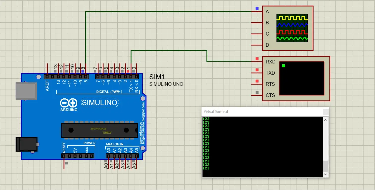
Simulation Results
Testing Results
Here is the result of running this interrupt latency measurement code example on my Arduino UNO board.
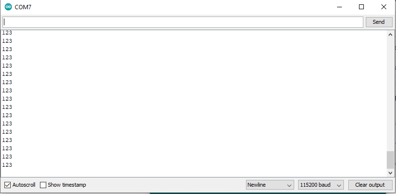
The simulation and real life test results are perfectly matching each other. The measured execution time for the TestFunction is therefore 123 timer ticks. Which means, Execution Time = 123/16,000,000 = 7.7μs. This is much closer to the result of the IO pin method which I consider to be the most accurate among all.
Therefore, the timer measurement is much better than micros() for short time intervals measurement. While the IO pin will give you the most accurate result at all but at the cost of being manual and require you to sit there holding the probe of a DSO and taking the measurement yourself.
Benchmark Function & Test Results Comparison
Before concluding this tutorial, I’ll show you a brief comparison for the test results using the same benchmark function that has a moderately intensive workload for the CPU. You know the AVR microcontroller doesn’t have a hardware floating-point unit to perform floating-point arithmetic and multiplication. Therefore the following test function is a good fit for what we want to do here.
|
1 2 3 4 5 6 7 8 9 10 11 12 |
#define LOOPS 1 float x=1.2345, y=6.789; void TestFunction(void) { //----[ Function Body]---- for(int i=0; i<LOOPS; i++) { x *= y; } //------------------------ } |
By changing the #define LOOPS value, we can prolong the execution time for this function. And that’s what I’ve done to get the following results. I let it run for 1, 10, and 100 loop counts. Every time, I’ve recorded the execution time measurement for each technique of the 3 that we’ve discussed in this article so far. The table below summarizes all the results.
| #LOOPs | IO Pin | Micros | Timer |
| 1 | 7.4μs | 10μs | 7.7μs |
| 10 | 66μs | 70μs | 66.6μs |
| 100 | 648μs | 652μs | 651μs |
To conclude this topic, we can say the following:
- The IO Pin Method: is the most accurate among all but it’s a bit slower because it needs the user to sit there with a DSO and take the measurement manually. This is perfectly fine if you’re developing a new algorithm or something and need a very accurate assessment of how optimized your code is.
- The Micros Method: is the easiest to implement among all, it’s automatic and can be reliable if the execution time to be measured is pretty much high. Otherwise, measuring very low time intervals will give you worse results than the timer method and the IO pin technique. It’s quick and easy to get a reasonable estimate without consuming many resources on the Arduino microcontroller.
- The Timer Method: is the overall best technique among all, it combines accuracy at low time interval measurement and it’s also automatic with no need for user intervention at all.
Parts List
Here is the full components list for all parts that you’d need in order to perform the practical LABs mentioned here in this article and for the whole Arduino Programming series of tutorials found here on DeepBlueMbedded. Please, note that those are affiliate links and we’ll receive a small commission on your purchase at no additional cost to you, and it’d definitely support our work.
Download Attachments
You can download all attachment files for this Article/Tutorial (project files, schematics, code, etc..) using the link below. Please consider supporting my work through the various support options listed in the link down below. Every small donation helps to keep this website up and running and ultimately supports our community.
Wrap Up
To conclude this tutorial, we’d like to highlight the fact that execution time measurement for various functions & ISR handlers can be very helpful to assess the CPU load or to help you identify how optimized your code is in terms of speed. Especially when you’re developing a new algorithm or a time-critical system that needs to react as quickly as possible.
If you’re just getting started with Arduino, you need to check out the Arduino Getting Started [Ultimate Guide] here.
This is the ultimate guide for getting started with Arduino for beginners. It’ll help you learn the Arduino fundamentals for Hardware & Software and understand the basics required to accelerate your learning journey with Arduino Programming.
For more information about Arduino Timers, fundamental concepts, different timers operating modes, and code examples, it’s highly recommended to check out the tutorial linked below. It’s the ultimate guide for Arduino Timers.
This article will give more in-depth information about Arduino Timers, how timers work, different timers operating modes, practical use cases and code examples, and everything you’d ever need to know about Arduino Timers.
![Arduino Timers Tutorial [Ultimate Guide] Arduino Timers Tutorial [Ultimate Guide]](https://deepbluembedded.com/wp-content/uploads/2023/05/Arduino-Timers-Tutorial-Ultimate-Guide-300x169.jpg)
