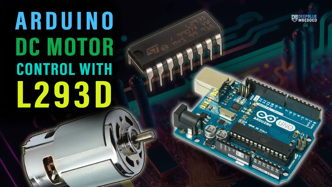
In this tutorial, you’ll learn how to do Arduino L293D Motor Driver IC Interfacing and use the L293D with Arduino to control the speed and direction of DC motors. And we’ll create a couple of Arduino DC Motor Control With L293D IC Projects using PWM for motor speed control.
Table of Contents
- Arduino DC Motor Control
- L293D Motor Driver IC
- L293D Motor Driver IC Pinout
- Wiring L293D Motor Driver IC With Arduino
- Arduino L293D + DC Motor Code Example
- Control 2 DC Motors Using Arduino & L293D IC
- Wrap Up
Arduino DC Motor Control
DC Motors are very simple rotary actuators that transform electrical energy into a mechanical rotation at a specific torque. We typically use DC motors for applications that require moving objects (e.g. Robotics, Automation, UAV/UGV, etc).
Controlling a DC motor includes: (1) controlling the motor’s speed, and (2) controlling the motor’s direction of rotation (CW or CCW). In this tutorial, you’ll learn how to control a DC motor’s speed & direction using Arduino and L293D motor driver IC.
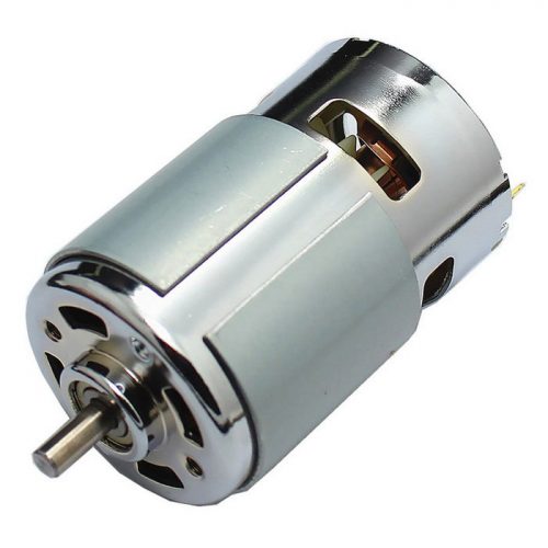
A typical DC motor will have the following characterstics:
- Torque (in kg.cm)
- Rated Rotation Speed (RPM)
- Rated Full-Load current (e.g. 2A)
- Rated No-Load current (e.g. 0.2A)
- Rated voltage for operation (e.g. 12v)
1- DC Motor Direction Control
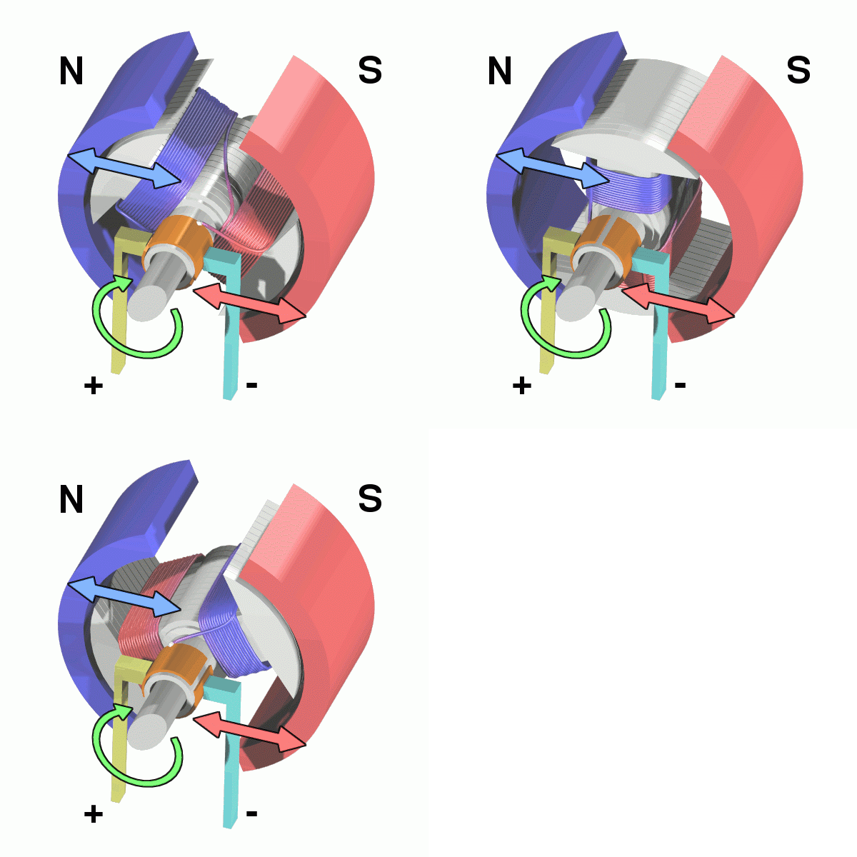
When electrical current passes through the motor’s winding (coils) that are arranged within a fixed magnetic field (Stator). The current generates a magnetic field in the coils. This in turn causes the coil assembly (Rotor) to rotate, as each coil is pushed away from the like-pole and attracted to the unlike-pole of the stator.
Reversing the direction of current flow in the coil translates to an inversion in the direction of the rotor’s magnetic field. Which in turn applies an inversed torque to each side of the coil resulting in a reverse direction in the rotation.
Arduino DC Motor Direction Control Using H-Bridge
To control the direction of a DC motor, you need to reverse the polarity of the input power source. This reversal of current flow causes the motor to rotate in the opposite direction.
There are various methods to achieve this polarity reversal in practical applications, such as using a motor driver IC or an H-bridge circuit. These methods provide a controlled and efficient way to reverse the motor’s direction while also offering additional functionalities like speed control and braking.
An H-Bridge motor driver circuit is an H-shaped circuitry in which the DC motor is hooked through 4 Switches/Transistors between the power rails ( VM & Ground ). Altering the activated switches reverses the polarity of the voltage (VM) applied to the DC Motor. Consequently, the rotation direction is reversed.
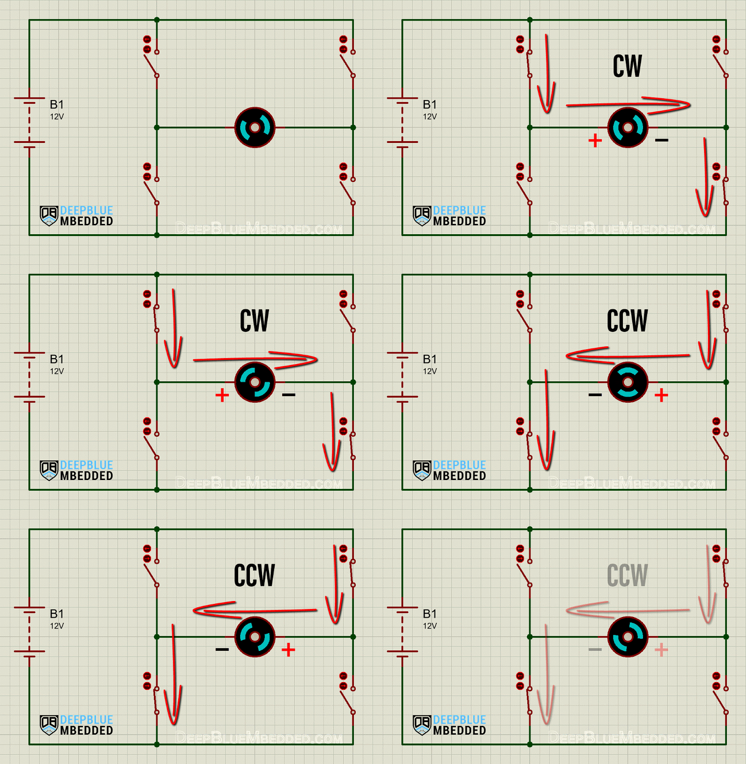
Actually, a real-world H-bridge circuit won’t have 4x ON/OFF switches. Instead, there will be 4-Transistors which are basically “electronic switches” doing the job of reversing the polarity of the motor supply voltage. Designing and building a fully-functioning H-Bridge circuit is beyond the intent of this tutorial.
Instead, we’ll be using a 2-channel H-Bridge motor driver IC called “L293D” which can be used to control the direction and speed of up to 2 DC motors at the same time. More details of this chip will be discussed later on in this tutorial.
2- DC Motor Speed Control
Controlling the speed of a DC motor is basically achieved in a couple of ways as shown below:
- Variable Supply Voltage
- Using PWM-Controlled Gate
1- Variable Supply Voltage: can be achieved using voltage regulation circuitries. However. there are too many limitations and drawbacks to such a method that make it less practical to pursue. But theoretically, it just works and does the job. Varying the supply voltage will definitely control the motor’s speed accordingly.
2- Using a PWM-Controlled Gate: This is the most common technique for motor control applications. It’s basically done by isolating one of the power source rails from the H-Bridge circuitry using a transistor. Hence, creating an open circuit with the (Ground or VM+).
In this way, activating the Control Gate (the EN transistor) will cause the H-Bridge to be powered-up then the motor will start rotating. Regardless of the direction of rotations, activating the control gate with a PWM signal will somehow control the average voltage being delivered from the supply to the motor through the control transistor.
Arduino DC Motor Speed Control Using PWM
We use Arduino PWM output to control the speed of a DC motor. By varying the duty cycle for the motor output enable transistor, we can achieve motor speed control as we’ll see hereafter in this tutorial.
Arduino boards have several PWM output pins usually. Those pins are designated with a (~) mark next to the pin number on the board. Before discussing how to use the PWM output pins, let’s first define what is the PWM technique and what are the properties of a PWM signal.
Pulse Width Modulation (PWM) is a technique for generating a continuous HIGH/LOW alternating digital signal and programmatically controlling its pulse width and frequency. Certain loads like (LEDs, DC Motors, etc) will respond to the average voltage of the signal which gets higher as the PWM signal’s pulse width is increased.
Average voltage:
PWM Duty Cycle:
50%
PWM Frequency:
x Hz
PWM Duty Cycle Resolution:
As you can see, the LED gets brighter as the pulse width (duty cycle) increases, and it gets dimmer as the pulse width decreases. And this is typically what also happens with a DC motor's speed, it gets faster or slower as the PWM's duty cycle changes.
Check the tutorial below to learn more about Arduino PWM. It's a prerequisite for this tutorial to help you understand the topic in more detail.
This tutorial will provide you with more in-depth information about Arduino PWM output. Starting from the basics of PWM signal, its frequency, duty cycle, and resolution, and will discuss in detail how it works and how to use it in various Arduino control projects.
L293D Motor Driver IC
The L293D is a dual-channel H-Bridge motor driver IC capable of driving two DC motors or a single bipolar stepper motor. The ability to drive two separate DC motors makes it an ideal solution for simple two-wheel robotic vehicles.
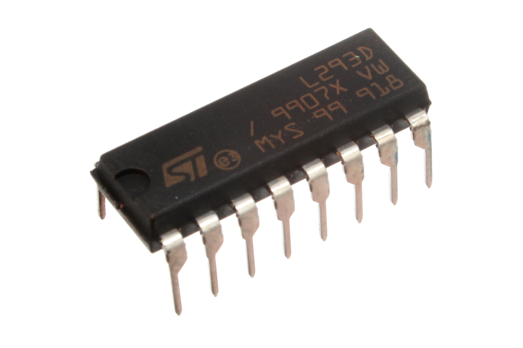
The L293D has a wide motor supply voltage range (4.5v to 36v) with a peak output current of 1.2A per channel. Each channel is rated to handle 0.6A of output current in normal operation and it can handle up to 1.2A of output current at maximum for a short period of time before it starts to heat up.
The L293D has internal temperature sensing and thermal shutdown to prevent over-drive damage to the chip. And it also has built-in flywheel diodes to protect the bridge's output transistors from inductive spikes that stem from switching inductive loads (DC Motor's Winding).
L293D Technical Specs.
| Motor Supply Voltage (VM) | 4.5v - 36v |
| Logic Input Voltage | 5v |
| Logic Supply Voltage (VCC) | 5v |
| Output Current Per Channel (IO) | 0.6A |
| Output Peak Current Per Channel (IOMax) Non-Continuous Current For Short Periods (t < 100 µs) | 1.2A |
For more information about the L293D motor driver IC, you can check its datasheet at Ti or STMicroelectronics.
L293D Motor Driver IC Pinout
Here is the pinout of the L293D motor driver IC.
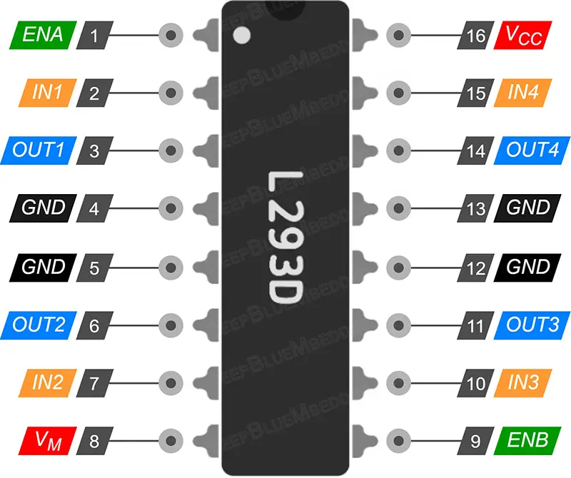
Let's break them down by functionality and discuss the usage of each pin in the L293D IC.
L293D Power Pins
VM is the motor supply pin. It can accept any voltage within the 4.5v to 36v range. This needs to be a separate supply other than the microcontroller's supply. While you can still connect it to the Arduino's 5v output but chances are high it'll damage your Arduino board by over-driving its LDO or induce a lot of noise to the 5v line that feeds the microcontroller and potentially cause it to randomly reset.
VCC is the logic supply pin. This pin should be connected to the 5v output of the Arduino board to supply the internal logic circuits inside the L293D motor driver IC.
GND are the ground pins. This pin should be connected to the ground of the Arduino board & the ground of the motor power supply (VM). There are 4 GND pins on the L293D IC two on each side to help in heat dissipation.
Motor Output Pins
OUT1 & OUT2 are the output pins of the first H-Bridge channel in L293D that connect to Motor1 terminals.
OUT3 & OUT4 are the output pins of the second H-Bridge channel in L293D that connect to Motor2 terminals.
Motor Enable Pins (Speed Control)
ENA & ENB are the motor output enable pins for Motor1 & Motor2 respectively. Those pins are used for motor speed control and they should be connected to PWM output pins on the Arduino board.
Motor Direction Control Pins
IN1 & IN2 are the Motor1 direction control pins. By setting or clearing those pins we can control the direction of rotation for Motor1 (Channel1).
IN3 & IN4 are the Motor2 direction control pins. By setting or clearing those pins we can control the direction of rotation for Motor2 (Channel2).
Here is the truth table for direction control input pins and what action the driver takes in each binary state combination for those input pins according to the L293D IC's datasheet.
| IN1 | IN2 | EN1 | Action |
| 0 | 1 | 1 | Turn CW |
| 1 | 0 | 1 | Turn CCW |
| 0 | 0 | 1 | Motor Brake |
| 1 | 1 | 1 | Motor Brake |
| X | X | 0 | Hi-Z (Motor Free-Run Stop) |
L293D Connection Example
Here is a typical connection diagram for the L293D motor driver IC that shows you which pin connects to what in a 2-motor system.
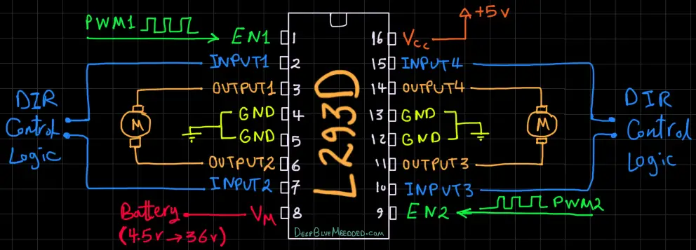
Wiring L293D Motor Driver IC With Arduino
Here is the wiring diagram for Arduino with L293D motor driver IC. Note that the DC motor is being driven by the L293D IC which is taking a 12v DC from an external power supply. Also, note that the ground of the external power supply is connected to the ground of the Arduino board.
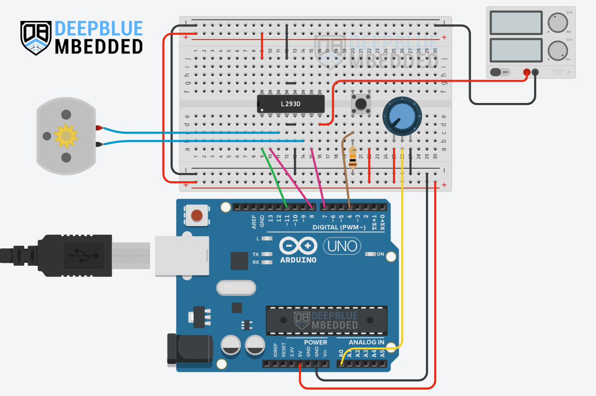
Arduino L293D + DC Motor Code Example
In this example project, we'll use Arduino & L293D motor driver IC to control the direction and speed of a 12v DC Motor. A push button will be used to flip the rotation direction of the motor. And a potentiometer will be used to control the motor's speed.
The input button debouncing technique that we'll be using in this project is demonstrated in the tutorial linked below as well as many other button debouncing techniques. It's a great tutorial that is worth checking out if you'd like to go deeper into this subject.
This article will provide you with more in-depth information about Arduino button debouncing techniques both hardware & software methods. With a lot of code examples & circuit diagrams.
The core logic of this application which takes input button pin reading, debouncing, applying control signals to the L293D, and changing the PWM duty cycle according to the ADC's reading for the analog input (potentiometer) is executed at a fixed time interval of 5ms instead of using delays.
We'll use the built-in timer-based millis() function to achieve this timing behavior without inserting any sort of delay into the code. If you'd like to learn more about this, it's highly recommended to check out this tutorial.
Wiring
The wiring for this example project is shown in the previous section, scroll up and check it out.
Code Example
Here is the full code listing for this example.
|
1 2 3 4 5 6 7 8 9 10 11 12 13 14 15 16 17 18 19 20 21 22 23 24 25 26 27 28 29 30 31 32 33 34 35 36 37 38 39 40 41 42 43 |
/* * LAB Name: Arduino DC Motor Control With L293D Driver IC * Author: Khaled Magdy * For More Info Visit: www.DeepBlueMbedded.com */ #define BTN_PIN 4 #define IN1_PIN 8 #define IN2_PIN 7 #define EN1_PIN 11 unsigned long T1 = 0, T2 = 0; uint8_t TimeInterval = 5; // 5ms void setup() { pinMode(BTN_PIN, INPUT); pinMode(EN1_PIN, OUTPUT); pinMode(IN1_PIN, OUTPUT); pinMode(IN2_PIN, OUTPUT); digitalWrite(IN1_PIN, HIGH); digitalWrite(IN2_PIN, LOW); } void loop() { T2 = millis(); if( (T2-T1) >= TimeInterval) // Every 5ms { // Read The Direction Control Button State if (debounce()) { digitalWrite(IN1_PIN, !digitalRead(IN1_PIN)); digitalWrite(IN2_PIN, !digitalRead(IN2_PIN)); } // Read The Potentiometer & Control The Motor Speed (PWM) analogWrite(EN1_PIN, (analogRead(A0)>>2)); T1 = millis(); } } bool debounce(void) { static uint16_t btnState = 0; btnState = (btnState<<1) | (!digitalRead(BTN_PIN)); return (btnState == 0xFFF0); } |
Code Explanation
First of all, we define the 4 IO pins used for the Arduino-L293D motor driver interfacing & the push button input reading.
|
1 2 3 4 |
#define BTN_PIN 4 #define IN1_PIN 8 #define IN2_PIN 7 #define EN1_PIN 11 |
And we'll also define a couple of variables that we'll use to store timestamps to execute the applications core logic at a fixed time interval ( TimeInterval = 5ms ). The way it works is extensively demonstrated in this tutorial.
|
1 2 |
unsigned long T1 = 0, T2 = 0; uint8_t TimeInterval = 5; // 5ms |
setup()
in the setup() function, we'll set the pinMode for the IO pins and initialize the motor direction control output pins (IN1 & IN2).
|
1 2 3 4 5 6 |
pinMode(BTN_PIN, INPUT); pinMode(EN1_PIN, OUTPUT); pinMode(IN1_PIN, OUTPUT); pinMode(IN2_PIN, OUTPUT); digitalWrite(IN1_PIN, HIGH); digitalWrite(IN2_PIN, LOW); |
loop()
in the loop() function, we'll check the timer-based millis function to execute the core logic every 5ms. Every 5ms, we'll read the push button input pin & debounce it. If the button is clicked by the user, we'll toggle the output direction control pins to flip the motor rotation direction (CW <-> CCW).
We'll also read the analog input (potentiometer) pin and scale down the 10-Bits value of the ADC down to 8-Bits to write it back to the output PWM pin's duty cycle to control the motor's speed according to the potentiometer's position.
|
1 2 3 4 5 6 7 8 9 10 11 12 13 14 |
void loop() { T2 = millis(); if( (T2-T1) >= TimeInterval) // Every 5ms { // Read The Direction Control Button State if (debounce()) { digitalWrite(IN1_PIN, !digitalRead(IN1_PIN)); digitalWrite(IN2_PIN, !digitalRead(IN2_PIN)); } // Read The Potentiometer & Control The Motor Speed (PWM) analogWrite(EN1_PIN, (analogRead(A0)>>2)); T1 = millis(); } } |
debounce()
This function is used to debounce the push button input pin and it's explained in great detail in this tutorial.
|
1 2 3 4 5 6 |
bool debounce(void) { static uint16_t btnState = 0; btnState = (btnState<<1) | (!digitalRead(BTN_PIN)); return (btnState == 0xFFF0); } |
TinkerCAD Simulation
You can check this simulation project on TinkerCAD using this link.
Testing Results
Control 2 DC Motors Using Arduino & L293D IC
Everything is the same as the previous example project, the only difference is that we'll introduce an additional DC Motor that will be connected to the second channel of the L293D Motor driver IC. We'll also add a second push button to control the direction of the newly added DC Motor and an additional potentiometer to control its speed.
Even the code will be the same, but some parts will be repeated to handle the logic operations needed to control the second motor that will add in this project compared to the previous one.
Wiring
Here is the wiring diagram for this example project. It's similar to the previous project's wiring but with an additional DC motor and its control signals from the Arduino to the L293D motor driver IC.
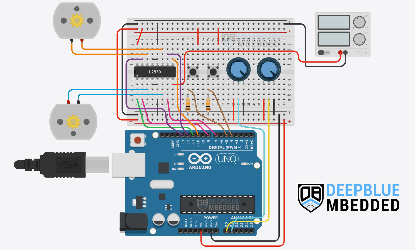
Code Example
|
1 2 3 4 5 6 7 8 9 10 11 12 13 14 15 16 17 18 19 20 21 22 23 24 25 26 27 28 29 30 31 32 33 34 35 36 37 38 39 40 41 42 43 44 45 46 47 48 49 50 51 52 53 54 55 56 57 58 59 |
/* * LAB Name: Arduino 2 DC Motors Control With L293D Driver IC * Author: Khaled Magdy * For More Info Visit: www.DeepBlueMbedded.com */ #define BTN1_PIN 4 #define BTN2_PIN 5 #define IN1_PIN 8 #define IN2_PIN 7 #define IN3_PIN 12 #define IN4_PIN 13 #define EN1_PIN 11 #define EN2_PIN 10 unsigned long T1 = 0, T2 = 0; uint8_t TimeInterval = 5; // 5ms uint16_t Btn1_State, Btn2_State; void setup() { pinMode(BTN1_PIN, INPUT); pinMode(BTN2_PIN, INPUT); pinMode(EN1_PIN, OUTPUT); pinMode(EN2_PIN, OUTPUT); pinMode(IN1_PIN, OUTPUT); pinMode(IN2_PIN, OUTPUT); pinMode(IN3_PIN, OUTPUT); pinMode(IN4_PIN, OUTPUT); digitalWrite(IN1_PIN, HIGH); digitalWrite(IN2_PIN, LOW); digitalWrite(IN3_PIN, HIGH); digitalWrite(IN4_PIN, LOW); } void loop() { T2 = millis(); if( (T2-T1) >= TimeInterval) // Every 5ms { // Read The Direction Control Button1 State if (debounce(&Btn1_State, BTN1_PIN)) { digitalWrite(IN1_PIN, !digitalRead(IN1_PIN)); digitalWrite(IN2_PIN, !digitalRead(IN2_PIN)); } // Read The Direction Control Button2 State if (debounce(&Btn2_State, BTN2_PIN)) { digitalWrite(IN3_PIN, !digitalRead(IN3_PIN)); digitalWrite(IN4_PIN, !digitalRead(IN4_PIN)); } // Read The Potentiometers & Control The Motors Speed (PWM) analogWrite(EN1_PIN, (analogRead(A0)>>2)); analogWrite(EN2_PIN, (analogRead(A1)>>2)); T1 = millis(); } } bool debounce(uint16_t* btnState, uint8_t btnPin) { *btnState = (*btnState<<1) | (!digitalRead(btnPin)); return (*btnState == 0xFFF0); } |
TinkerCAD Simulation
Testing Results
Parts List
Here is the full components list for all parts that you'd need in order to perform the practical LABs mentioned here in this article and for the whole Arduino Programming series of tutorials found here on DeepBlueMbedded. Please, note that those are affiliate links and we'll receive a small commission on your purchase at no additional cost to you, and it'd definitely support our work.
Download Attachments
You can download all attachment files for this Article/Tutorial (project files, schematics, code, etc..) using the link below. Please consider supporting my work through the various support options listed in the link down below. Every small donation helps to keep this website up and running and ultimately supports our community.
Wrap Up
To conclude this tutorial, we can say that you can easily control DC Motors with Arduino & L293D Motor Driver IC using PWM and some IO pins. To learn more about Arduino PWM, it's highly recommended that you check out this Arduino PWM Tutorial.
If you're just getting started with Arduino, you need to check out the Arduino Getting Started [Ultimate Guide] here.
And follow this Arduino Series of Tutorials to learn more about Arduino Programming.
This is the ultimate guide for getting started with Arduino for beginners. It'll help you learn the Arduino fundamentals for Hardware & Software and understand the basics required to accelerate your learning journey with Arduino Programming.
FAQ & Answers
The L293D is a dual-channel DC Motor Driver IC that's commonly used in Arduino projects to control the direction & speed of DC Motors. It has a wide power supply voltage range (4.5v To 36v) and can deliver a continuous current of 0.6A per channel and it handles up to 1.2A of peak current. It has a thermal shutdown feature as well as integrated flywheel diodes to protect the bridge from inductive spikes while switching the motor ON & OFF.
To control the speed of a DC motor using Arduino, you'll need a motor driver (a simple transistor or a dedicated driver IC like L293D) and a PWM output pin. By varying the duty cycle of the PWM, the average voltage on the motor will change causing the speed to go up and down accordingly. This is called open-loop control as we increase/decrease the motor's speed without having any idea of what actually is the current speed of the motor.
On the other hand, a closed-loop control for DC Motor with Arduino can be achieved by adding a motor speed sensor (e.g. optical encoder) and using a control algorithm like PID to regulate the motor's speed to make it follow a certain level set by the user (set-point) and the motor's speed (RPM) is known at all time in this type of control (closed-loop) unlike the open-loop method.
To control a DC motor with Arduino without a driver, you need at least to have a transistor to control the motor's speed using any PWM output pin of the Arduino. To control the direction of rotation, however, you'll need to build a polarity-inversion circuit to achieve this. The motor polarity inversion can be achieved with a 2-Relay circuit or a 4x transistor H-Bridge that you can also build on your own.
To control L293D with Arduino, you need 2 free IO pins for the direction control inputs (IN1 & IN2), and one PWM output pin for the speed control input pin on the L293D IC (EN1). This is a total of 2 io pins + 1 PWM pin per channel of the L293D which has a dual-channel H-Bridge for controlling up to 2 DC motors simultaneously.
The L293D motor driver IC is used for DC motor control applications that require up to 2 output channels. As the L293D motor driver has a dual-channel H-Bridge to control up to 2 motors independently. It's commonly used in low-power motor driver applications as it can only deliver up to 0.6A per channel for each motor at any given time before it starts to heat up. The L293D is usually used for two-wheeled simple robotic platforms (cars) thanks to its dual-channel bridge which reduces the circuit complexity & number of the required external components.
