This tutorial is the definitive guide for Arduino ADC & analogRead() For Analog Input Voltage. We’ll start off by explaining how an ADC work, what are the Arduino ADC characteristics and how to make the best use of it. We’ll also discuss the analogRead() function and how to use it for reading analog inputs with Arduino.
Then, we’ll implement a couple of Arduino example projects (LED Dimmer, and DC Motor Speed Control) Using Arduino ADC & analogRead. You’ll also learn a lot of tips and tricks for Arduino ADC & analogRead that will help you in your Arduino measurement projects. It’s a fundamental topic in this Arduino Programming Series of Tutorials, so make sure you get the hang of it. And let’s get right into it!
Table of Contents
- Introduction To ADC
- Arduino ADC (Analog To Digital Converter)
- Arduino analogRead() Function
- Arduino Analog Input (Reading Analog Voltage)
- Arduino ADC Example – LED Dimmer
- Arduino ADC Example – DC Motor Speed Control
- Remarks on Arduino ADC (analogRead)
- Arduino ADC (analogRead) Wrap Up
Introduction To ADC
An ADC (Analog to Digital Converter) is an electronic circuit that’s usually integrated into different microcontrollers or comes in as a dedicated IC. We typically use an ADC in order to measure/read the analog voltage from different sources or sensors.
Most parameters and variables are analog in nature and the electronic sensors that we use to capture this information are also analog. Just like temperature, light, pressure, and other sensors are all analog.
Therefore, we need to read the analog voltage value using our digital microcontrollers. And this is when we start learning about the ADC peripheral and try to configure it so as to get this task done.
The ADC does the inverse operation of a DAC. While an ADC (A/D) converts analog voltage to digital data, the DAC (D/A) converts digital numbers to an analog voltage on the output pin.

This is an in-depth article (tutorial) on ADC, how it works, different types of ADC, error sources, sampling, and much more. Consider checking it out if it’s your first time learning about the ADC.
This tutorial will provide you with more in-depth information about ADC (A/D) converters, types of ADC, how they work, ADC sampling, quantization, ADC errors, and much more.
Arduino ADC (Analog To Digital Converter)
The ADC (Analog to Digital Converter) in Arduino is used to read analog voltage input and convert it to its digital representation. This is essential for interfacing various types of sensors and modules with Arduino which provide an analog voltage output.
The Arduino UNO (atmega328p microcontroller) has a total of 6 analog input pins that are internally connected to the ADC to be used for reading analog voltage inputs. The Arduino’s internal ADC is 10 Bits in resolution, which means it has an output range of 0 up to 1023.
The analog voltage reference for Arduino ADC is by default VREF = +5v, which means we can measure analog input voltage up to 5v. Above that limit, the input pins can get damaged and the ADC output will saturate at 1023 anyway. So you need to be careful and stay within the working voltage limits.
In this section, we’ll dive deeper into the Arduino ADC characteristics and parameters to make the best use of it and to also know its fundamental limitations.
Arduino ADC Resolution
The Arduino ADC resolution is 10 bits, the digital output range is therefore from 0 up to 1023. And the analog input range is from 0v up to 5v (which is the default analog reference voltage VREF = +5v).
You can use the interactive tool below to set an analog input voltage and see the ADC digital output value that corresponds to the analog input voltage. The output equation for the ADC is as follows: ADC Output = ( Analog input voltage / VREF ) x (2n – 1). Where VREF = 5v and n is the ADC resolution which is 10bits.
Arduino ADC Reference Voltage
The AREF (Analog Reference) pin can be used to provide an external reference voltage for the analog-to-digital conversion of inputs to the analog pins (A0-A5). The reference voltage essentially specifies the maximum analog input voltage after which the ADC’s output will saturate at 1023.

Let’s recall the ADC’s output equation which is: ADC Output = ( Analog input voltage / VREF ) x (2n – 1). Where the “default” VREF = 5v and n is the ADC resolution which is 10bits.
Using the AREF pin we can change the default VREF voltage and set it to any desired voltage level which allows for more precise A/D conversions. Let’s say we hook up the AREF pin to an external 2.5v DC supply, now we’ll end up having double the resolution of the default 5v analog reference.
Because instead of dividing the 0v-5v range into discrete 1024 digital levels, we’ll now divide the 0v-2.5v range into discrete 1024 digital levels. Which is exactly double the default resolution. But you must make sure that the input analog voltage will not exceed 2.5v after setting the AREF to 2.5v. Otherwise, the ADC will saturate at 1023 if the analog input voltage exceeds the new AREF (2.5v).
Use the interactive ADC tool above to test it yourself and see the effect of lowering the AREF voltage from 5v down to 2.5v and how it increases the ADC resolution by a factor of 2.
| VREF | Analog Input Voltage | ADC Digital Output |
| 5v | 0.01v | 2 |
| 2.5v | 0.01v | 4 |
For the exact same analog input (0.01v), you get more ADC ticks (levels) at VREF=2.5v compared to VREF=5v. This is what we mean by the resolution being doubled (increased by a factor of 2).
Arduino ADC Sampling Time
The ADC in Arduino or any other microcontroller can’t just convert the analog voltage on a pin that is continuously changing. Therefore, it needs to take a snapshot of the analog voltage on the pin at a specific moment and store that voltage in a small capacitor (Sampling Capacitor “CS“). The voltage copy on the capacitor will remain constant after the sampling switch (SSW) is opened.
Therefore, the ADC will have a stable copy of the analog input pin voltage available on the CS capacitor and it can start conversion with no issue. The whole process of closing the sampling switch SSW until the sampling capacitor is charged to the exact same voltage level of the input pin, then reopening the SSW again is what we call ADC Sampling.
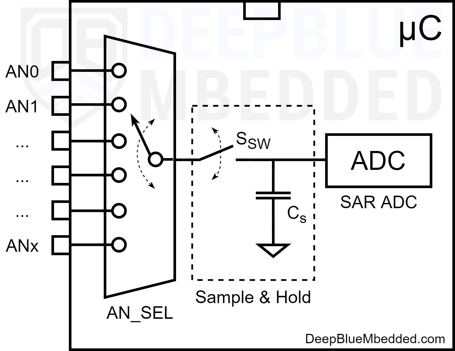
As stated in the Atmega328p datasheet, the ADC sampling time is around 1.5 to 2 ADC Clocks. Given that the default ADC Clock Speed (in Arduino UNO) is 125kHz, therefore, the ADC Sampling Time is 16μs.
The ADC has a maximum clock speed of 200kHz, but it needs to run at a lower clock frequency in order to achieve the 10-bit resolution. That’s why the Arduino ADC default clock frequency is set to 125kHz.
Arduino ADC Conversion Time
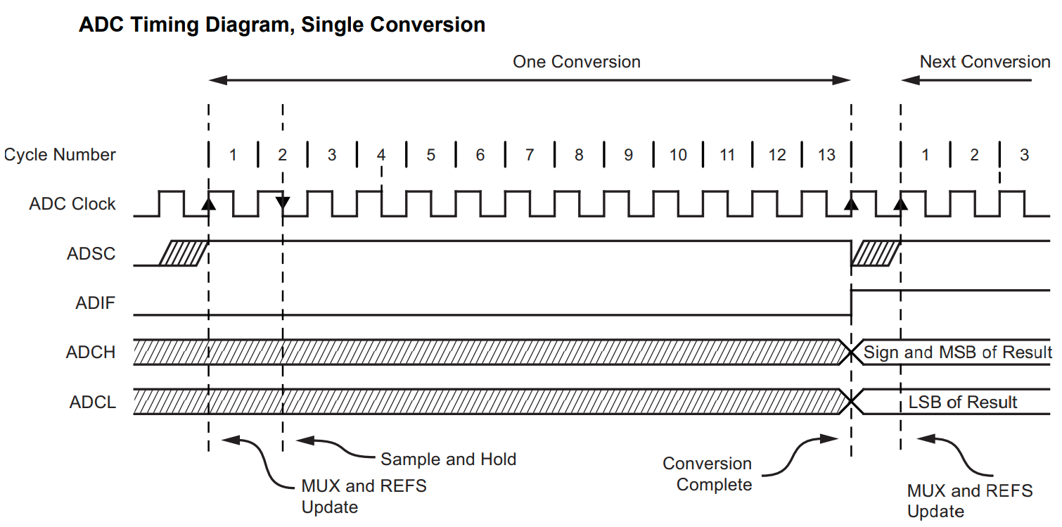
The ADC conversion time usually refers to the time it takes the ADC to complete a single A/D conversion operation. The sampling process that we’ve discussed in the previous section is part of the ADC conversion process. It actually proceeds the SOC (start of conversion) that triggers the SAR (successive approximation register) ADC to start its operation.
The SAR ADC takes around 11.5 ADC clocks to complete a single 10-Bit A/D conversion process. Add to that the sampling time which is 1.5 ADC clock. Therefore, we end up with a conversion time of 13 ADC Clocks.
Given that the default ADC Clock Speed (in Arduino UNO) is 125kHz, therefore, the ADC Conversion Time is 104μs. Which is the typical (default) ADC conversion time for Arduino UNO (atmega328p).
Arduino ADC Sampling Rate
The ADC Sampling Rate is a measure of an ADC speed which means the number of conversions (samples) that the ADC can take per second. And it’s expressed in ksps or Msps (kilo or Mega Samples Per Second).
To find out the ADC’s maximum sampling rate, we’ll run it at the maximum ADC clock speed (which is 200kHz). Given that a single A/D conversion takes 13 ADC Clocks, therefore the conversion time at maximum speed is 65μs.
Therefore, the Arduino ADC Sampling Rate is 15.4k samples per second. (1/65μs)
Arduino ADC Speed
The Arduino ADC speed also refers to the ADC’s sampling rate. By default, the ADC clock is 125kHz, resulting in a conversion time of 104μs. And therefore, the Arduino ADC default Speed is 9,600 samples per second.
By increasing the ADC clock speed, we’ll be sacrificing some resolution (accuracy) of course, but this will definitely increase the ADC Speed. At maximum ADC clock speed (200kHz), the conversion time goes down to 65μs). And therefore, the Arduino ADC Max Speed is 15,400 samples per second.
Arduino ADC Analog Pins
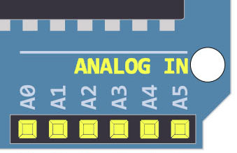
The Arduino UNO has 6 analog input pins labeled from A0 to A5 as shown in the figure below. Those pins can be used with analog peripherals in the Arduino microcontroller such as ADC (A/D Converter) and the Analog Comparator.
Arduino analogRead() Function
Reads the value from the specified analog pin. Arduino boards contain a multichannel, 10-bit ADC. This means that it will map the analog input voltages between 0 and the VREF voltage (5V or 3.3V) into integer values between 0 and 1023.
On an Arduino UNO, for example, this yields a resolution between readings of (5 volts / 1024 units) or, 0.0049 volts (4.9 mV) per unit. In other words, the smallest input voltage change that the ADC can sense is around 4.9 mV.
analogRead Syntax
|
1 |
analogRead(pin); |
analogRead Parameters
pin: the name of the analog input pin to read from (A0 to A5 on most boards, A0 to A6 on MKR boards, A0 to A7 on the Mini and Nano, A0 to A15 on the Mega).
analogRead Example
|
1 |
AN0_Result = analogRead(A0); |
analogRead Return
The analog reading on the pin. Although it is limited to the resolution of the analog to digital converter (0-1023 for 10 bits or 0-4095 for 12 bits). Data type: int.
Arduino analogRead Range
The analogRead() function returns a value within the 10 bits resolution range (0 – 1023).
Which corresponds to an analog input voltage range (0v – 5v).
Arduino analogRead Speed
To measure, the analogRead() function speed, I’ve developed the measurement code example below. Which uses Arduino Direct Pin Manipulation to toggle an IO pin before and after 4x calls to the analogRead() function “to be measured”.
The resulting pulse waveform is captured by my oscilloscope and we’ll get the pulse width and divide it by 4 to get the total execution time of the analogRead() function.
Here is the code example for analogRead() speed measurement.
|
1 2 3 4 5 6 7 8 9 10 11 12 13 14 15 16 17 18 19 20 21 22 23 24 25 26 27 |
/* * LAB Name: Arduino AnalogRead Speed Measurement * Author: Khaled Magdy * For More Info Visit: www.DeepBlueMbedded.com */ // ---[ Arduino Pin Manipulation Macros ]--- #define SET_PIN_MODE_OUTPUT(port, pin) DDR ## port |= (1 << pin) #define SET_PIN_HIGH(port, pin) (PORT ## port |= (1 << pin)) #define SET_PIN_LOW(port, pin) ((PORT ## port) &= ~(1 << (pin))) int AN0_Result = 0; void setup() { SET_PIN_MODE_OUTPUT(B, 0); // Set Pin8 (PB0) As Output } void loop() { SET_PIN_HIGH(B, 0); AN0_Result = analogRead(A0); AN0_Result = analogRead(A0); AN0_Result = analogRead(A0); AN0_Result = analogRead(A0); SET_PIN_LOW(B, 0); delay(5); } |
Here is the result after running this code on my Arduino UNO board and taking the measurement on my DSO.
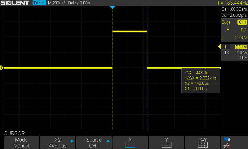
It’s around 448μs for the 4x calls to the analogRead() function. Therefore, the analogRead() speed is 112μs.
Given that the ADC default A/D conversion time is 104μs as we’ve seen earlier, the analogRead() function takes another 8μs for housekeeping logic operations, CPU context switching, and such.
This tutorial will provide you with more in-depth information about Arduino direct port & pin manipulation. You’ll learn how to measure the execution time of any function in your Arduino projects. And also to control the IO pins extremely faster than the generic digitalWrite() and digitalRead().
Arduino Analog Input (Reading Analog Voltage)
Now, let’s move to reading actual analog input voltage using Arduino ADC analog input pins. We’ll divide this section into 3 parts for all possible sinareos and how to deal with each case to maximize the ADC measurements accuracy.
In your projects you’ll be dealing with different levels of analog voltages that you may need to measure with the ADC analog input pins. The analog voltage input can fall into one of the following categories:
- Typical Range (0v – 5v)
- High Voltage (>5v)
- Small Signal (<1v)
And you need to deal with each type of analog input voltage in a different way to get accurate and reliable results of the ADC.
Arduino Analog Input (Typical Range 0v-5v)
For analog input voltage within the typical range of (0v – 5v), you just connect the “to be measured” voltage signal to the Arduino’s analog input pin directly. And you can just read the pin using the analogRead() function. Here is an example:
|
1 2 3 4 5 6 7 8 9 10 11 12 13 14 |
int AN0_Result = 0; float AN0_Voltage = 0; void setup() { // NOTHING To Do } void loop() { AN0_Result = analogRead(A0); AN0_Voltage = AN0_Result * (5 / 1024); delay(10); } |
No extra care is needed while dealing with a signal in the typical default range (0v – 5v).
Arduino Analog Input (High Voltage >5v)
If you need to measure an analog voltage that’s higher than 5v, you just can’t hook it up to the Arduino analog input pin for two reasons. First of which and most importantly, it’s going to damage the IO pin which can’t handle any voltage above +5.5v. And secondly, the ADC will saturate at 1023 the moment you reach 5v on the input pin, any voltage change above that won’t induce a change in the ADC reading that will stay at 1023.
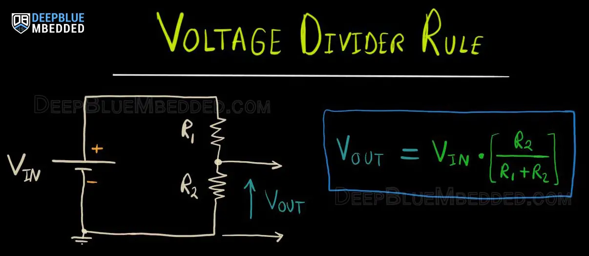
Attenuate The Input Voltage (Voltage Divider)
The proper way to read high voltage using Arduino’s ADC is to create a voltage divider network to attenuate the “to be measured” voltage with a specific ratio. So that the voltage present on the analog input pins falls within the (0v – 5v) range. Now, it’s easy to read the analog input voltage on the pin and reconstruct the actual “to be measured” voltage by multiplying the measured voltage by the attenuation ratio.
Arduino Analog Input (Small Signal <1v)
If you’re reading a sensor or an electronic device that has a small signal output voltage (less than 1v), the Arduino’s ADC in default settings will not be sufficient for this task. You’ll be losing a lot of resolution actually because of the default VREF being 5v.
Go back to the Arduino ADC interactive tool, set the VREF to 5v, and change the input voltage slider up and down within the 1v range. You’ll notice that we’re leaving 80% of the ADC range completely unused!
1- Reduce The VREF To Enhance The Resolution
By reducing the VREF down to 1v, you can see that we’re now using the full ADC range and the measurement resolution has improved significantly. At the default VREF = 5v setting, the minimum voltage change the ADC could sense was 4.88mv. After reducing the VREF down to 1v, the ADC can now sense down to 1mv of change in the analog input voltage.
2- Amplify The Input Signal
Another solution, would be to amplify the input signal itself. Especially if we’re talking about a few mv analog input signal. This is extremely challenging for the Arduino’s 10-Bit ADC. But it becomes doable and much easier if we amplify the small signal with an Op-Amp based signal conditioning circuit.
This will indeed facilitate the job of our ADC to measure the voltage that was a few millivolts and now became (0v – 5v). But it brings in some new challenges that we need to deal with. Things like Op-Amp zero-drift, nonlinearity, early saturation, etc.
Arduino ADC Example – LED Dimmer
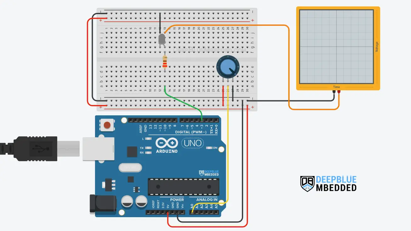
In this example project, we’ll control an LED brightness with an Arduino PWM output pin. We’ll use a potentiometer and the analogRead() function to get the potentiometer reading and use it to control the PWM’s duty cycle for LED Dimming.
Wiring
Here is the wiring diagram for this example showing how to connect the LED output, the potentiometer analog input, and the oscilloscope channel.
Code Example
Here is the full code listing for this example.
|
1 2 3 4 5 6 7 8 9 10 11 12 13 14 15 16 |
/* * LAB Name: Arduino LED Dimmer (Potentiometer + PWM) * Author: Khaled Magdy * For More Info Visit: www.DeepBlueMbedded.com */ #define LED_PIN 3 void setup() { pinMode(LED_PIN, OUTPUT); } void loop() { analogWrite(LED_PIN, (analogRead(A0)>>2)); } |
Code Explanation
First of all, we define the IO pin used for the LED output. It has to be a PWM-enabled IO pin (for UNO: 3, 5, 6, 9, 10, or 11).
|
1 |
#define LED_PIN 3 |
setup()
in the setup() function, we’ll set the pinMode to be output.
|
1 |
pinMode(LED_PIN, OUTPUT); |
loop()
in the loop() function, we’ll read the analog input pin of the potentiometer (which is 10-Bit resolution) and convert it to 8-Bit resolution by dividing by 4 (or right-shifting twice “ >>2”). Now, we’ve mapped the analog input value to the PWM duty cycle range.
Using Arduino analogWrite() function, we’ll write back the ADC scaled reading as a duty cycle for the PWM to control the speed of the motor accordingly.
|
1 |
analogWrite(LED_PIN, (analogRead(A0)>>2)); |
We can test this project’s code example using any available Arduino simulator environment. Here I’ll show you the simulation results for this project on both TinkerCAD and Proteus (ISIS).
TinkerCAD Simulation
You can check this simulation project on TinkerCAD using this link.
Proteus (ISIS) Simulation
Another extremely powerful simulation environment for Arduino is the Proteus (ISIS) with Arduino add-on library. It can definitely run our test projects for this tutorial. But you won’t feel its power until you need some virtual test equipment like an oscilloscope, function generator, power supply, and advanced SPICE simulation for auxiliary electronic circuitry that you may build around an Arduino microcontroller.
Here is the Arduino project simulation result from the Proteus environment.
Testing Results
Check out the tutorial below to help you get started with simulating your Arduino projects in the Proteus simulation environment.
This article will provide you with more in-depth information about using proteus ISIS for Arduino projects simulation.
Arduino ADC Example – DC Motor Speed Control
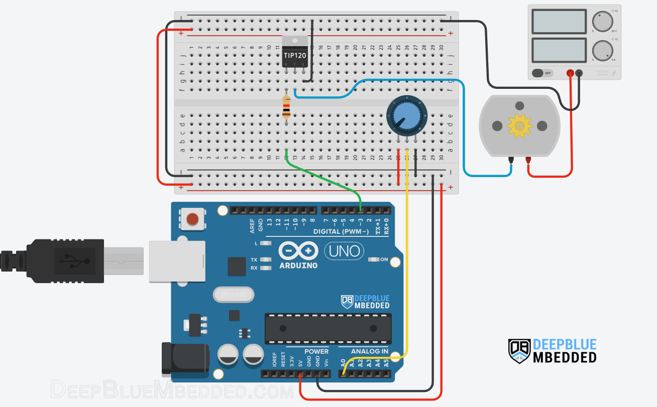
In this example project, we’ll control a DC Motor’s speed with an Arduino PWM output pin + a BJT Transistor. We’ll use a potentiometer and the analogRead() function to get the potentiometer reading and use it to control the PWM’s duty cycle and consequently the motor’s speed.
Wiring
Here is the wiring diagram for this example showing how to connect the BJT Transistor (TIP120) with the DC Motor, Battery, and Arduino PWM output pin. Pay attention to the common ground between the external power source (battery) and the Arduino board.
Example Code
Here is the full code listing for this example.
|
1 2 3 4 5 6 7 8 9 10 11 12 13 14 15 16 |
/* * LAB Name: Arduino PWM DC Motor Speed Control * Author: Khaled Magdy * For More Info Visit: www.DeepBlueMbedded.com */ #define MOTOR_PWM_PIN 3 void setup() { pinMode(MOTOR_PWM_PIN, OUTPUT); } void loop() { analogWrite(MOTOR_PWM_PIN, (analogRead(A0)>>2)); } |
Code Explanation
First of all, we define the IO pin used for the motor speed control output. It has to be a PWM-enabled IO pin (for UNO: 3, 5, 6, 9, 10, or 11).
|
1 |
#define MOTOR_PWM_PIN 3 |
setup()
in the setup() function, we’ll set the pinMode to be output.
|
1 |
pinMode(MOTOR_PWM_PIN, OUTPUT); |
loop()
in the loop() function, we’ll read the analog input pin of the potentiometer (which is 10-Bit resolution) and convert it to 8-Bit resolution by dividing by 4 (or right-shifting twice). Now, we’ve mapped the analog input value to the PWM duty cycle range.
Using Arduino analogWrite() function, we’ll write back the ADC scaled reading as a duty cycle for the PWM to control the speed of the motor accordingly.
|
1 |
analogWrite(MOTOR_PWM_PIN, (analogRead(A0)>>2)); |
Simulation
Here is the simulation result for this project on the TinkerCAD simulator. Don’t pay much attention to the motor rotation animation, it may not be rendered in real-time or it’s spinning really fast so we can’t judge the motor speed or anything other than the DC current drawn from the power supply which correlates with the speed change.
You can check this simulation project on TinkerCAD using this link.
Testing Results
Here is the result of testing this project code example on my Arduino UNO board.
Remarks on Arduino ADC (analogRead)
Before concluding this tutorial, let’s highlight some facts and more advanced topics about the ADC that you can research to expand your knowledge or to solve a challenging issue in your current project.
I may dedicated separate tutorials for any of the following topics depending on your questions and requests. So feel free to ping me if something here is of interest to you and you’d like to dig deeper in a specific area. This will always be most welcomed!
1- Arduino ADC Accuracy
The Arduino (Atmega328p) microcontroller’s datasheet states that the ADC has an absolute accuracy of ±2 LSB. At the default VREF = +5v, the LSB in ADC reading means the measured analog voltage is 4.88v. Therefore the accuracy of ±2 LSB means ±9.75mv in the measured voltage.
This can be easily verified if you’ve got a reference standard voltage source that you can compare the Arduino’s ADC against.
2- ADC Dynamic Range Bad Matching
To obtain the maximum ADC conversion accuracy, it is very important that the ADC dynamic range matches the maximum amplitude of the signal to be converted. Let us assume that the signal to be converted varies between 0 V and 2.5 V and the VREF = 5V.
The maximum signal value converted by the ADC is 512 (2.5V) as shown in the diagram down below. In this case, there are 511 unused transitions (1023 – 512 = 511). This implies a loss in the converted signal accuracy.
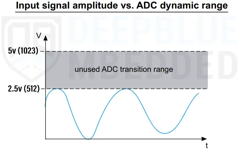
To make the best use of your ADC, set the VREF in such a way that it barely covers the “to be measure” analog input signal’s range.
3- Arduino ADC Errors
There are a few error sources in the ADC measurements that are inherent in the ADC hardware construction itself. It has some non-ideal characteristics that causes the A/D conversion result to drift a little bit away from what it should be. Those errors include the following:
- ADC Offset Error
- ADC Gain Error
- ADC Integral Non-Linearity (INL)
- ADC Differential Non-Linearity (DNL)
And you can do further research for the reason behind each error type and different ways of mitigation. The Atmega328p microcontroller’s datasheet should be a good starting point.
4- Arduino ADC Max Input Impedance
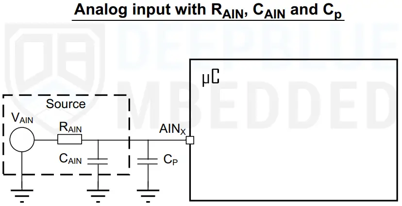
The impedance of the analog signal source, or series resistance (RAIN), between the source and pin, causes a voltage drop across it because of the current flowing into the pin. The charging of the internal sampling capacitor (CS) is controlled by switches with a resistance RADC. With the addition of source resistance (with RADC), the time required to fully charge the hold capacitor increases.
If the sampling time (ts) is less than the time required to fully charge the CS through RADC + RAIN (ts < tc), the digital value converted by the ADC will be less than the actual voltage value on the pin.

This error can be reduced or completely eliminated by setting the sampling time of the analog channel in such a way that guarantees an appropriate voltage level on the input pin is present before the ADC starts the conversion. But unfortunately, this option is not available in Arduino (Atmega328p) microcontroller, so we only have to reduce the ADC clock itself.
As stated in the Arduino (Atmega328p) microcontroller’s datasheet, the ADC hardware is optimized to deal with up to 10kΩ input impedance for any analog input channel. However, you can still go beyond that limit but you’ll have to increase the ADC sampling time, which is not possible, and now you’re forced into reducing the global ADC clock frequency.
The takeaway from this section is to try minimizing the resistance in the analog input path to the ADC. For example: when picking a potentiometer, a 10kΩ pot will definitely be better than a 100kΩ one, and so on.
5- Analog Signal Source Capacitance & ADC Parasitics
When converting analog signals, it is necessary to account for the capacitance at the source and the parasitic capacitance seen on the analog input pin. The source resistance and capacitance form an RC network. In addition, the ADC conversion results may not be accurate unless the external capacitor (CAIN + Cp) is fully charged to the level of the input voltage.
The greater value of (CAIN + Cp), the more limited the source frequency. The external capacitance at the source and the parasitic capacitance are denoted by CAIN and Cp, respectively.
6- Arduino ADC Injection Current Effect
A negative injection current on any analog pin (or a closely positioned digital input pin) may introduce leakage current into the ADC input. The worst case is the adjacent analog channel. A negative injection current is introduced when VAIN < VSS, causing current to flow out from the I/O pin. Which can potentially shift the voltage level on the pin and distort the measurement result.
7- Arduino ADC Cross-Coupling
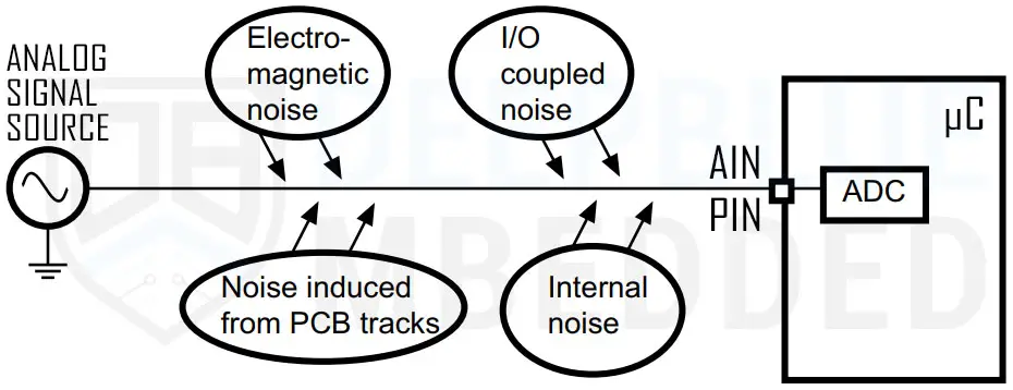
Switching the I/Os may induce some noise in the analog input of the ADC due to capacitive coupling between I/Os. Crosstalk may be introduced by PCB tracks that run close to each other or that cross each other.
Internally switching digital signals and IOs introduces high-frequency noise. Switching high sink I/Os may induce some voltage dips in the power supply caused by current surges. A digital track that crosses an analog input track on the PCB may affect the analog signal.
Very short ADC sampling time can also cause some analog input channels to pick up some voltage from each other. Because the internal sampling capacitor (CS) is not completely charged to the input pin voltage. This is also another way of cross-coupling and it can be prevented by increasing the ADC sampling time. Note that Arduino doesn’t support variable programmable sampling time, so you may need to change the ADC clock frequency divider instead.
8- ADC EMI-Induced Noise
Electromagnetic emissions from neighboring circuits may introduce high-frequency noise in an analog signal because the PCB tracks may act as an antenna. It’s called electromagnetic interference (EMI) noise. The ADC analog input pins are more sensitive and susceptible to pick up such a noise.
Parts List
Here is the full components list for all parts that you’d need in order to perform the practical LABs mentioned here in this article and for the whole Arduino Programming series of tutorials found here on DeepBlueMbedded. Please, note that those are affiliate links and we’ll receive a small commission on your purchase at no additional cost to you, and it’d definitely support our work.
Download Attachments
You can download all attachment files for this Article/Tutorial (project files, schematics, code, etc..) using the link below. Please consider supporting my work through the various support options listed in the link down below. Every small donation helps to keep this website up and running and ultimately supports our community.
Arduino ADC (analogRead) Wrap Up
To conclude this tutorial, we’d like to highlight the fact that you can easily read analog input signals with Arduino using the analogRead() function. Which converts the analog voltage on the input pin (0v – 5v) and returns it as a digital value (0 – 1023).
This tutorial is a fundamental part of our Arduino Series of Tutorials because we’ll use it in so many tutorials and projects hereafter. So make sure, you’ve learned all the concepts and implemented the practice examples whether on your Arduino board or at least in the simulation environment.
If you’re just getting started with Arduino, you need to check out the Arduino Getting Started [Ultimate Guide] here.
And follow this Arduino Series of Tutorials to learn more about Arduino Programming.
This is the ultimate guide for getting started with Arduino for beginners. It’ll help you learn the Arduino fundamentals for Hardware & Software and understand the basics required to accelerate your learning journey with Arduino Programming.
FAQ & Answers
The Arduino ADC (Analog to Digital Converter) is a peripheral in the Arduino’s microcontroller that takes an analog input voltage on a pin and converts it to a digital value. We typically use an ADC in order to measure/read the analog voltage from different sources or sensors.
Arduino UNO has an ADC type called SAR (Successive Approximation Register) with a resolution of 10 bits.
The Arduino analogRead() function allows the user to read an ADC channel (pin) and convert the analog voltage input to its digital representation and return that value. It’s got a range of (0 – 1023) that corresponds to analog input voltages (0v – 5v).
