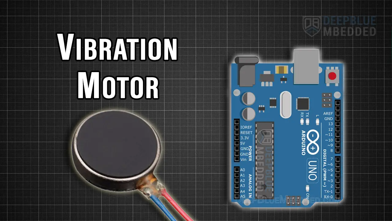
In this tutorial, you’ll learn how to do Arduino Vibration Motor Control and use the Vibration Motor with Arduino to turn it ON/OFF and control the vibration strength. We’ll also create an Arduino Vibration Motor Example Project which can be a very good starting point for your Arduino Haptic Feedback project idea. Without further ado, let’s get right into it!
Table of Contents
- Introducing Vibration Motor
- Arduino Vibration Motor Circuit Diagram
- Arduino Vibration Motor Control Code Example
- Arduino Vibration Motor Strength Control
- Concluding Remarks
Introducing Vibration Motor
A Vibration Motor is a compact device that generates mechanical vibrations through the use of an electric motor with an unbalanced mass on its drive shaft. Primarily used in a wide range of applications to provide haptic feedback to make the user interface a lot more engaging to the end user.
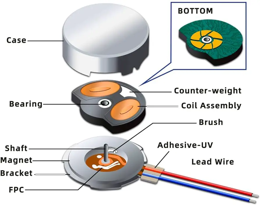
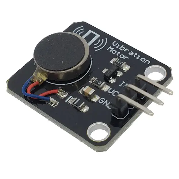
The figure above shows you the internal structure of a small Vibration Motor that’s found in cell phone devices which happens to be the same as the mini Vibration motor that we also use in various projects (with Arduino, ESP32, etc). Below is an image of the small Vibration motor that we’ll be using in this tutorial (on the left side). The image on the right side is also for the same mini vibration motor but it’s soldered on a PCB with a driver transistor control circuit to make it easier for interfacing with various microcontrollers.
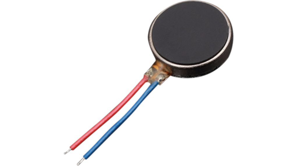
Vibration Motor Technical Specs
- Rated Voltage: 1.5 – 4VDC (3V typical)
- Rated Current: 80mA @ 3V
Vibration Motor Applications
- Haptic Feedback
- Alarm Systems
- Remote Controllers
- Interactive HMI
Buy a Vibration Motor: you can find it here on Amazon.com
Arduino Vibration Motor Circuit Diagram
Here is the wiring diagram for the Arduino Vibration Motor control circuit using a BJT transistor as a driver switch. Note that the Vibration Motor is being driven by the BJT transistor which is taking a 5v DC from the Arduino UNO board. You can also use the 3.3v supply output pin for a weaker, but safer, drive of the vibration motor.
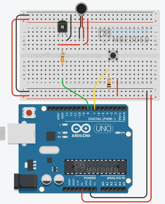
It’s highly recommended to check out this Arduino + Transistor Tutorial to learn more about how to use BJT transistors with Arduino in your projects, how to calculate the base resistor’s value, and much more.
This article will give more in-depth information about BJT transistors and how to use NPN/PNP transistors with Arduino to control various devices.
Arduino Vibration Motor Control Code Example
In this example project, we’ll use an Arduino + Vibration Motor with a BJT 2N3904 output driver transistor. A push button will be used to turn the Vibration Motor ON and OFF making it active as long as the button is held down.
The core logic of this application is taking the input button pin reading, and applying control signals to the BJT output driver transistor that turns ON and OFF the Vibration Motor.
Vibration Motor Wiring
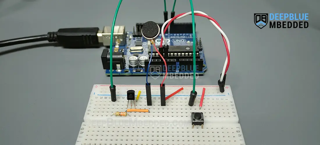
The wiring diagram for this example project is shown in the previous section, scroll up and check it out. Below is an image of how the whole setup looks like at the end, ready for the test.
Code Example
Here is the full code listing for this example.
|
1 2 3 4 5 6 7 8 9 10 11 12 13 14 15 16 17 18 19 20 |
/* * LAB Name: Arduino Vibration Motor Control * Author: Khaled Magdy * For More Info Visit: www.DeepBlueMbedded.com */ #define BTN_PIN 7 #define MOT_PIN 8 void setup() { pinMode(BTN_PIN, INPUT); pinMode(MOT_PIN, OUTPUT); } void loop() { while(digitalRead(BTN_PIN)) { digitalWrite(MOT_PIN, HIGH); } digitalWrite(MOT_PIN, LOW); } |
Code Explanation
First of all, we define the 2 IO pins used for the Arduino-Vibration Motor BJT Transistor driver & the push button input reading.
|
1 2 |
#define BTN_PIN 7 #define MOT_PIN 8 |
setup()
in the setup() function, we’ll set the pinMode for the IO pins.
|
1 2 |
pinMode(BTN_PIN, INPUT); pinMode(EM_PIN, OUTPUT); |
loop()
in the loop() function, we’ll check the button’s input pin state and enable the Vibration Motor’s driver (TIP120 BJT Transistor) as long as the button is held down (state= HIGH). When the button is released (state = LOW), we’ll get out of the while loop already and we’ll drive the motor’s output to LOW in order to turn it OFF.
|
1 2 3 4 5 6 7 |
void loop() { while(digitalRead(BTN_PIN)) { digitalWrite(MOT_PIN, HIGH); } digitalWrite(MOT_PIN, LOW); } |
TinkerCAD Simulation
Here is the simulation result for this project on the TinkerCAD simulator. You can run it as is, or make a copy, add your own code, and start running the simulation to see how it’s going to behave.
You can check this simulation project on TinkerCAD using this link.
Testing Results
You need to make sure that your vibration motor is fixed in place because it can easily jump out of the circuit or induce mechanical stress on its really weak leads causing them to be torn. Usually, a vibration motor is trapped in a plastic fixture or glued to a surface using super glue.
Arduino Vibration Motor Strength Control
Can I use Arduino PWM output to control the vibration strength of a vibration motor? The answer is YES, you can. Using a variable duty cycle PWM output from your Arduino board with the BJT transistor output driver will result in a variable vibration strength on the vibration motor.
Consider adding a Fly-Back Diode in parallel with your vibration motor in case you’re going to use a PWM signal to control the vibration strength. This diode will protect your output driver transistor from inductive spikes that the motor is going to generate.
Required Parts List
Here is the full components list for all the parts that you’d need to perform the practical LABs mentioned here in this article and for the whole Arduino Programming series of tutorials found here on DeepBlueMbedded. Please, note that those are affiliate links and we’ll receive a small commission on your purchase at no additional cost to you, and it’d definitely support our work.
Download Attachments
You can download all attachment files for this Article/Tutorial (project files, schematics, code, etc..) using the link below. Please consider supporting my work through the various support options listed in the link down below. Every small donation helps to keep this website up and running and ultimately supports our community.
Concluding Remarks
To conclude this tutorial, we can say that you can easily control a Vibration Motor with Arduino and an output driver transistor. The Vibration Motor’s vibration strength can be controlled in a variable way using a PWM signal. To learn more about Arduino PWM, it’s highly recommended that you check out this Arduino PWM Tutorial.
If you’re just getting started with Arduino, you need to check out the Arduino Getting Started [Ultimate Guide] here.
And follow this Arduino Series of Tutorials to learn more about Arduino Programming.
