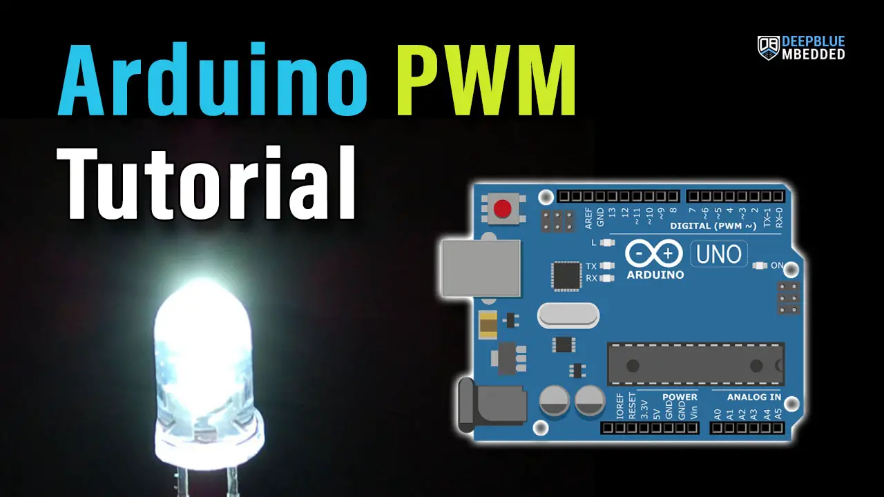
In this tutorial, you’ll learn how to use Arduino PWM analog output pins using the analogWrite() function. We’ll start from the basics of PWM signal, its frequency, duty cycle, and resolution, and discuss in detail how it works and how to use it in various Arduino control projects.
Pulse Width Modulation (PWM) is a fundamental topic in Embedded Systems and Arduino programming for electronics. This tutorial will help you fully understand it and apply some practice examples and projects on your own. Without further ado, let’s get right into it!
Table of Contents
- Arduino PWM Fundamentals
- Arduino analogWrite() Function – PWM Output
- Arduino PWM – LED Brightness Control Example
- Arduino PWM Wrap Up
Arduino PWM Fundamentals
Arduino boards have several PWM output pins usually. Those pins are designated with a (~) mark next to the pin number on the board. Before discussing how to use the PWM output pins, let’s first define what is the PWM technique and what are the properties of a PWM signal.
Introduction to PWM
Pulse Width Modulation (PWM) is a technique for generating a continuous HIGH/LOW alternating digital signal and programmatically controlling its pulse width and frequency. Certain loads like (LEDs, Motors, etc) will respond to the average voltage of the signal which gets higher as the PWM signal’s pulse width is increased.
This technique is widely used in embedded systems to control LEDs brightness, motor speed, and other applications. And here is a graphical animation that shows you the effect of a PWM signal on an LED’s brightness.

As you can see, the LED gets brighter as the pulse width (duty cycle) increases, and it gets dimmer as the pulse width decreases. And this is typically what we use the PWM output for.
PWM Frequency
The PWM signal you’ve seen above captures a few features. The first of which is the frequency, which is basically a measure of how fast the PWM signal keeps alternating between HIGH and LOW. The frequency is measured in Hz and it’s the inverse of the full period time interval. Here is how it looks graphically and its mathematical formula.

We control the Arduino PWM frequency using dedicated PWM libraries. And this can be important in a lot of applications because the switching frequency of the PWM can have a huge impact on the Switching Device and/or the Load itself.
- A switching device like a MOSFET transistor will get hotter due to more power loss (switching losses) at higher PWM frequencies.
- Certain loads like DC motors can act weirdly at high PWM frequencies as well.
- Electronics tend to generate audible noise if the PWM switching signal’s frequency is within the audible range 20Hz-20kHz. So we usually set the PWM frequency above that range.
All in all, there are good reasons why we need and will control the PWM output signal’s frequency.
PWM Duty Cycle
The PWM’s duty cycle is the most important feature that we’re always interested in. It’s a measure of how long the PWM signal stays ON relative to the full PWM’s cycle period. The PWM’s duty cycle equation is as follows:

The duty cycle is usually expressed as a percentage (%) value because it’s a ratio between two-time quantities. And it directly affects the PWM’s total (average) voltage that most devices respond to. That’s why we typically change the duty cycle to control things like LED brightness, DC motor speed, etc.
The Arduino’s PWM has a resolution of 8 bits by default, which means the duty cycle can have any value between 0 and 255. We write a 0 to get a 0% duty cycle, 255 to get a 100% duty cycle, and any value in between will have the same mapping.
PWM Resolution
The PWM resolution is expressed in (bits). It’s the number of bits that are used to represent the duty cycle value. It can be 8bits, 10, 12, or even 16bits. The PWM resolution can be as the number of discrete duty cycle levels between 0% and 100%. The higher the PWM resolution, the higher number of discrete levels over the entire range of the PWM’s duty cycle.
A PWM resolution of only 3bits means there are only 8 discrete levels for the duty cycle over the entire range (from 0% up to 100%). On the other hand, a PWM with a resolution of 8 bits will have 256 discrete levels for the duty cycle over the entire range (from 0% up to 100%). You can use the interactive tool below to test this yourself.
Average voltage:
PWM Duty Cycle:
50%
PWM Frequency:
x Hz
PWM Duty Cycle Resolution:
Set the PWM resolution to 3-bit and sweep across the entire range of PWM's duty cycle. And change the resolution up to 8 bits or even 16 bits to see the huge difference in the degree of control you'll have over the duty cycle value. It becomes incredibly smooth as the resolution increases and we become more able to fine-tune the duty cycle. You can use the keyboard arrow keys for fine adjustment of the duty cycle while testing high resolutions.
As you have seen, a higher PWM resolution is always a desirable thing to have. However, it's always in inverse proportion to the PWM's frequency. The higher the PWM frequency you choose, the lower the PWM resolution becomes. There is no way to go around this fact.
All you need to know for now is that the Arduino PWM default settings will give you an 8-Bit resolution PWM signal. This means that the duty cycle value will be between (0 to 255). And it's sufficient for most control applications.
I'll dedicate a separate tutorial to this topic for those who'd love to go deeper into this area.
Arduino PWM Pins
The pins indicated by the “~” on the Arduino board are the PWM output pins. There are 6 PWM output pins on the Arduino UNO board (pins 3, 5, 6, 9, 10, and 11).

This is a table for the PWM pins available in different Arduino boards and the default PWM output frequency for those pins.
| Arduino Board | PWM Pins | PWM Default Frequency |
| Uno, Nano, Mini | 3, 5, 6, 9, 10, 11 | 490 Hz (pins 5 and 6: 980 Hz) |
| Mega | 2 - 13, 44 - 46 | 490 Hz (pins 4 and 13: 980 Hz) |
| Leonardo, Micro, Yún | 3, 5, 6, 9, 10, 11, 13 | 490 Hz (pins 3 and 11: 980 Hz) |
Arduino PWM Applications
There are so many applications that you can create with Arduino PWM outputs. It's generally essential in most control applications including, but not limited to, the following list of applications:
- LED Brightness Control
- Generating Audio Signals
- Generating Analog Waveforms (PWM+RC)
- DC Motor Speed Control
- Servo Motor Control
- Brushless ESC Controllers
- RGB LED Strip Control
- DC-DC Converters
And the list goes on. There are so many applications that you can create with Arduino PWM outputs and we'll be discussing a lot of them in this Arduino programming series of tutorials. But in this tutorial, let's get started with the analogWrite() function to see how it works. Then, we'll implement the first basic PWM output example project for LED brightness control.
Arduino analogWrite() Function - PWM Output
Writes an analog value (PWM's duty cycle) to a pin. Can be used to light an LED at varying brightnesses or control a DC motor's speed. After a call to the analogWrite() function, the pin will generate a steady PWM signal with the specified duty cycle until the next call to analogWrite() to update the duty cycle value.
analogWrite Syntax
analogWrite(pin, value);
analogWrite Parameters
pin: the Arduino pin to write to. Allowed data types:
int.
value: the duty cycle: between 0 (always off) and 255 (always on). Allowed data types:
int.
analogWrite Example
analogWrite(3, 128); // Writes 128 (50% DutyCycle) To PWM Output Pin3
Arduino PWM output is also called Analog Output and this is most likely because of its analogWrite() function. However, it's not an analog output, it's still a digital (HIGH/LOW) signal. The effect of the PWM signal on some devices that respond to the average voltage of the PWM makes it seem like an analog output despite the fact that it's a digital signal in nature.
Arduino PWM - LED Brightness Control Example
In this example project, we'll control an LED brightness with an Arduino PWM output pin. Using two for loops, we'll gradually increase the duty cycle from 0% up to 100%. Then, gradually decrease it from 100% down to 0%. And keep repeating!
So, let's put what we've learned so far to practice and see the results on the LED and use an oscilloscope to check the output PWM signal as well.
Wiring
Here is the wiring diagram for this example showing how to connect the LED output and the oscilloscope channel.

Example Code
Here is the full code listing for this example.
/*
 * LAB Name: Arduino PWM LED Brightness Control Example
 * Author: Khaled Magdy
 * For More Info Visit: www.DeepBlueMbedded.com
*/
#define LED_PIN 3

void setup()
{
  pinMode(LED_PIN, OUTPUT);
}

void loop()
{
  // Gradually Increase Duty Cycle
  for(int i=0; i<255; i++)
  {
    analogWrite(LED_PIN, i);
    delay(5);
  }
  // Gradually Decrease Duty Cycle
  for(int i=255; i>0; i--)
  {
    analogWrite(LED_PIN, i);
    delay(5);
  }
}
Code Explanation
First of all, we define the IO pin used for the LED output. It has to be a PWM-enabled IO pin (for UNO: 3, 5, 6, 9, 10, or 11).
#define LED_PIN 3
setup()
in the setup() function, we'll set the pinMode to be output.
pinMode(LED_PIN, OUTPUT);
loop()
in the loop() function, we'll create 2 for loops. The first for loop will gradually increase the output PWM's duty cycle with a small 5ms delay time after every PWM duty cycle update operation. The second loop will gradually decrease the output PWM's duty cycle from 100% down to 0%, and everything will repeat forever.
// Gradually Increase Duty Cycle
for(int i=0; i<255; i++)
{
  analogWrite(LED_PIN, i);
  delay(5);
}
// Gradually Decrease Duty Cycle
for(int i=255; i>0; i--)
{
  analogWrite(LED_PIN, i);
  delay(5);
}
Simulation
Here is the simulation result for this project on the TinkerCAD simulator.
You can check this simulation project on TinkerCAD using this link.
Testing Results
Here is the result of testing this project code example on my Arduino UNO board.
As you have might noticed in the demo video testing, The PWM signal's frequency is 490Hz exactly. Which is what we expect as a default frequency on pin3.
Parts List
Here is the full components list for all parts that you'd need in order to perform the practical LABs mentioned here in this article and for the whole Arduino Programming series of tutorials found here on DeepBlueMbedded. Please, note that those are affiliate links and we'll receive a small commission on your purchase at no additional cost to you, and it'd definitely support our work.
Download Attachments
You can download all attachment files for this Article/Tutorial (project files, schematics, code, etc..) using the link below. Please consider supporting my work through the various support options listed in the link down below. Every small donation helps to keep this website up and running and ultimately supports our community.
Arduino PWM Wrap Up
To conclude this tutorial, we'd like to highlight the fact that you can easily generate PWM signals with Arduino using the analogWrite() function. Which generates a fixed-frequency PWM signal that we can change its duty cycle from 0 up to 255. This tutorial is a fundamental part of our Arduino Series of Tutorials because we’ll use it in so many tutorials and projects hereafter. So make sure, you’ve learned all the concepts and implemented the practice examples whether on your Arduino board or at least in the simulation environment.
If you're just getting started with Arduino, you need to check out the Arduino Getting Started [Ultimate Guide] here.
And follow this Arduino Series of Tutorials to learn more about Arduino Programming.
FAQ & Answers
PWM (Pulse Width Modulation) is a technique for generating a continuous HIGH/LOW alternating digital signal and programmatically controlling its pulse width and frequency. Certain loads like (LEDs, Motors, etc) will respond to the average voltage of the signal which gets higher as the PWM signal's pulse width is increased.
The default PWM Frequency in Arduino is 490Hz (for Pins 3, 9, 10, and 11). The default PWM Frequency for pins 5 and 6 is 980Hz. However, you can still control the PWM's frequency using additional PWM libraries to help you achieve any desired output PWM frequency.
The PWM duty cycle value in Arduino is 8-Bit, so it ranges from 0 up to 255. This is called the PWM Resolution as well. The PWM resolution is limited by hardware timer specification and also the PWM frequency setting. At the Arduino default PWM frequency (490Hz), the resolution is 8 Bits. In other words, there are 256 discrete levels to control the PWM's duty cycle.
Check your Arduino board IO pins. The pins with the (~) mark next to their number are PWM output pins. To generate a PWM signal output on any of these pins, you have to do the following:
1- Set the pin in output mode using the pinMode(pin, OUTPUT) function.
2- Use the analogWrite(pin, dutyCycle) function to set the PWM duty cycle value.
And now you'll have a PWM signal on the specified pin with the specified duty cycle.