In this tutorial, we’ll discuss Arduino External Interrupt Pins from the fundamental concepts all the way to implementing interrupt-based systems. We’ll start off by discussing what are interrupts, and how they work.
We’ll create a couple of Arduino External Interrupt Example Projects in this tutorial to practice what we’ll learn all the way through. Without further ado, let’s get right into it!
Table of Contents
- How Interrupts Work?
- Arduino External Interrupts
- Using Arduino External Interrupts
- Arduino External Interrupts Code
- Arduino External Interrupt Example
- Arduino External Interrupts Wrap Up
How Interrupts Work?
The interrupt handling mechanism in Arduino (Atmega328p) microcontroller is illustrated in the figure below. And it goes like this:
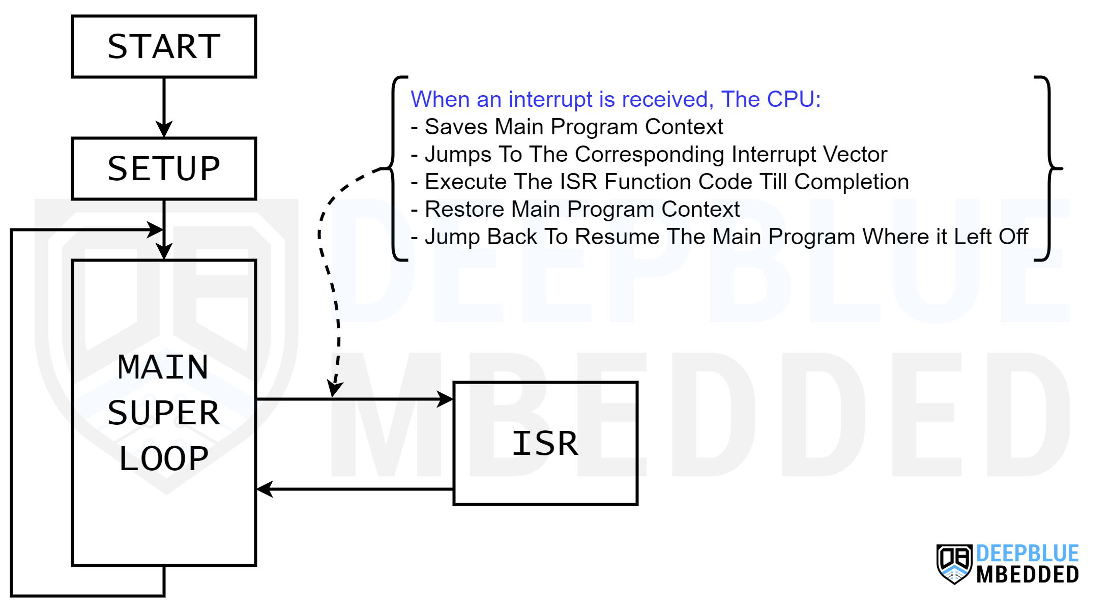
When the microcontroller’s CPU receives an interrupt signal, it pauses the main program execution and saves its current context.
The CPU then jumps to the interrupt vector (address) where the corresponding ISR handler function is located. And starts executing that ISR handler function till completion.
Then, the CPU restores back the context of the main program and jumps back to where it left off the main program. And everything resumes as it used to before the arrival of the interrupt signal.
When a new interrupt is fired, the CPU will immediately be notified and all previous steps will be repeated again. Otherwise, the CPU will keep executing the main program (super loop() function).
This is the complete Arduino Interrupts Tutorial. It’ll provide you with more in-depth information about interrupts in general and specifically in Arduino, how it works, how to write efficient ISR handlers, and other tips & tricks.
Arduino External Interrupts
Internal Interrupts
Internal interrupts are generated by internal events within the microcontroller itself, such as timers, ADC, UART, or any other peripheral events.
External Interrupts
External interrupts on the other hand are triggered by external signals applied to specific pins of the microcontroller. Those pins are usually referred to as IRQ pins (interrupt request pins). Which directly fire interrupt signals to the CPU when a certain external event occurs, that’s why those interrupts are known as external interrupts.
The most common types of IRQ pins are dedicated external interrupt pins and IOC (interrupt-on-change) pins. The difference is that dedicated external IRQ pins have separate interrupt vectors, while IRQ IOC pins share a common interrupt signal and you have to manually check which pin state has changed and caused that IOC global flag to fire the interrupt.
Using Arduino External Interrupts
Now, let’s see how to use externals Interrupts in Arduino, which functions are associated with external interrupts in Arduino (IRQ pins), trigger modes, and how to enable/disable interrupts in Arduino.
1. Arduino External Interrupt Pins
External interrupt pins in Arduino UNO are IO pin2 & pin3. They differ from one Arduino board to another, so here is a summarized table for the external interrupt pins available in each Arduino board.
| Arduino Board | External Interrupts Pins |
|---|---|
| Arduino Uno, Nano, Mini | 2, 3 |
| Arduino Mega | 2, 3, 18, 19, 20, 21 |
| Arduino Micro, Leonardo | 0, 1, 2, 3, 7 |
| Arduino Zero | All IO pins (except pin4) |
| Arduino Due | All IO pins |
Let’s take Arduino UNO as an example, it’s got (pins 2 & 3) that correspond to external interrupts (INT0 & INT1) respectively. Note that the interrupt vector number is different than the Arduino IO pin number itself. For this, we use the digitalPinToInterrupt() function that maps the IO pin number to the respective interrupt vector number automatically for us.
The PCINT (pin-change interrupt) is available in all IO pins across the entire Arduino board list. Still, you need to check the target microcontroller’s datasheet for further details regarding the pin-change interrupts.
2. External Interrupt Pin Trigger Modes
The Arduino external interrupt pins fire an interrupt when the digital state of the associated pin has changed. The pin change event that triggers an interrupt can be configured to have one of the following modes:
- RISING: Interrupt fires when the signal goes from LOW to HIGH
- FALLING: Interrupt fires when the signal goes from HIGH to LOW
- CHANGE: Interrupt fires when the signal changes (LOW -> HIGH or HIGH -> LOW)
- LOW: Interrupt fires whenever the signal is held LOW

This gives us (programmers) the flexibility to choose the pin change mode that suits the application we’re working on. Each interrupt trigger mode is useful in a particular system configuration. And below is an example to demonstrate this.
3. Arduino attachInterrupt() Function
The Arduino attachInterrupt() function is used to enable the external interrupt (IRQ) pins, only (INT0 & INT1).
Syntax
|
1 2 |
attachInterrupt(interrupt, ISR, mode); attachInterrupt(digitalPinToInterrupt(pin), ISR, mode); // More Recommended |
Parameters
interrupt: the number of the interrupt vector ( int).
pin: the pin number.
ISR: the ISR handler function to call when the interrupt occurs. This function must take no parameters and return nothing.
mode: defines when the interrupt should be triggered. Four constants are predefined as valid values:
- RISING to trigger when the pin goes from low to high,
- FALLING for when the pin goes from high to low.
- CHANGE to trigger the interrupt whenever the pin value changes
- LOW to trigger the interrupt whenever the pin is low,
The Due, Zero and MKR1000 boards allow also:
- HIGH to trigger the interrupt whenever the pin is high.
Example Code
|
1 2 3 4 5 6 7 8 9 10 11 12 13 14 15 16 17 18 |
#define LED_PIN 13 #define INT0_PIN 2 volatile byte state = LOW; void INT0_ISR() { state = !state; } void setup() { pinMode(LED_PIN, OUTPUT); pinMode(INT0_PIN, INPUT_PULLUP); attachInterrupt(digitalPinToInterrupt(INT0_PIN), INT0_ISR, CHANGE); } void loop() { digitalWrite(LED_PIN, state); } |
4. Arduino detachInterrupt() Function
The Arduino detachInterrupt() function is used to disable external interrupts (INTx) if being enabled earlier. This can be really useful if you no longer need the external interrupt pin in your application, it’s better to offload the CPU by shutting down interrupt sources that are no longer needed.
Syntax
|
1 2 |
detachInterrupt(interrupt); detachInterrupt(digitalPinToInterrupt(pin)); // More Recommended |
Parameters
interrupt: the number of the interrupt vector to be disabled ( int).
pin: the pin number of the interrupt to disable.
Check out the tutorial below to learn more about Arduino global interrupts enable/disable functions ( interrupts, noInterrupts, sei, and cli).
This article will give more in-depth information about Arduino global interrupts control using the Arduino noInterrupts, sei() & cli() functions.
Arduino External Interrupts Code
In this section, I’ll give you a step-by-step approach to what to do in order to configure and initialize an Arduino external interrupt pin and assign to it an ISR handler function.
Step 1– Decide on the external interrupt GPIO input pin that you’re going to use (INTx pin).
|
1 |
#define BTN_PIN 2 |
Step 2– Decide on the Interrupt Trigger Event that you need to have. (RISING – FALLING – LOW – CHANGE).
Step 3– Initialize that GPIO input pin & AttachInterrupt to it in the setup function.
|
1 2 3 4 5 |
void setup() { pinMode(BTN_PIN, INPUT); attachInterrupt(digitalPinToInterrupt(BTN_PIN), INT0_ISR, RISING); } |
Step 4– Now, write your own ISR handler function. In other words, what do you want to do when this input pin has a rising edge input?
|
1 2 3 4 |
void INT0_ISR(void) { // This is The ISR Handler, Do Whatever You Need To Do Here! } |
And that’s it! Let’s test this out in the following example project.
Arduino External Interrupt Example
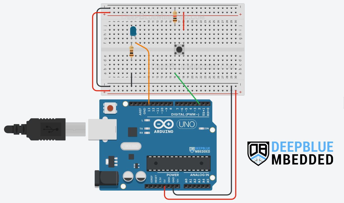
In this example project, we’ll test Arduino external interrupt pins & write an ISR function to handle it. We’ll use INT0 interrupt to toggle an LED output on every rising edge on the external interrupt input pin (hooked to a push button).
Wiring
Here is the wiring diagram for this example showing how to connect the LED output, and the push button to the interrupt input pin (INT0 = pin2).
Arduino External Interrupt Example Code
Here is the full code listing for this Arduino External Interrupt Example.
|
1 2 3 4 5 6 7 8 9 10 11 12 13 14 15 16 17 18 19 20 21 22 23 24 |
/* * LAB Name: Arduino External Interrupt Demo * Author: Khaled Magdy * For More Info Visit: www.DeepBlueMbedded.com */ #define LED_PIN 13 #define BTN_PIN 2 void INT0_ISR(void) { digitalWrite(LED_PIN, !digitalRead(LED_PIN)); } void setup() { pinMode(LED_PIN, OUTPUT); pinMode(BTN_PIN, INPUT); attachInterrupt(digitalPinToInterrupt(BTN_PIN), INT0_ISR, RISING); } void loop() { // Do Nothing } |
Code Explanation
We first need to define the IO pins to be used for the LED output & push button input (INT0 external interrupt pin = IO pin2).
|
1 2 |
#define LED_PIN 13 #define BTN_PIN 2 |
INT0_ISR()
This is the ISR handler function for the INT0 external interrupt in which we’ll only do a LED toggle action. For each RISING edge on the external interrupt pin (push button), the CPU will execute this ISR function which will toggle the output LED.
|
1 2 3 4 |
void INT0_ISR(void) { digitalWrite(LED_PIN, !digitalRead(LED_PIN)); } |
setup()
in the setup() function, we’ll initialize the IO pins to be used as input & output using the pinMode() function to set their modes.
|
1 2 |
pinMode(LED_PIN, OUTPUT); pinMode(BTN_PIN, INPUT); |
Then we’ll enable the external interrupt for the INT0 (pin2) using the attachInterrupt() function & set it to trigger on RISING edge events only.
|
1 |
attachInterrupt(digitalPinToInterrupt(BTN_PIN), INT0_ISR, RISING); |
loop()
in the loop() function, nothing needs to be done.
TinkerCAD Simulation
You can check this simulation project on TinkerCAD using this link.
Testing Results
This example project is a very good example to showcase the Button Bouncing issue & how it can affect your Arduino projects. And it also shows you that we can’t always rely on results from the simulation environment only as it’s not going to simulate such real-world random events and noise.
Note that this example project will behave in a weird way due to an issue that’s commonly known as “Button Bouncing“. This is simply a random event due to the button’s mechanical contacts bouncing, which results in some glitches or unintended pulses being injected into the digital input pin causing it falsely trigger the interrupt multiple times “randomly”.
Despite the fact that there are so many software button debouncing techniques (algorithms) that you can learn about from the guide below, it still won’t protect an external interrupt pin because the hardware bouncing is sending a random triggering signal to the interrupt circuitry. The best way to deal with it and prevent false interrupt triggering is to use hardware button debouncing which is also demonstrated in the guide tutorial below with a lot of examples.
This article will provide you with more in-depth information about Arduino button debouncing techniques both hardware & software methods. With a lot of code examples & circuit diagrams.
This article will provide you with more in-depth information about interrupt latency & response time. With a couple of techniques for interrupt latency measurement with Arduino code examples.
Parts List
Here is the full components list for all parts that you’d need in order to perform the practical LABs mentioned here in this article and for the whole Arduino Programming series of tutorials found here on DeepBlueMbedded. Please, note that those are affiliate links and we’ll receive a small commission on your purchase at no additional cost to you, and it’d definitely support our work.
Download Attachments
You can download all attachment files for this Article/Tutorial (project files, schematics, code, etc..) using the link below. Please consider supporting my work through the various support options listed in the link down below. Every small donation helps to keep this website up and running and ultimately supports our community.
Arduino External Interrupts Wrap Up
To conclude this tutorial, we’d like to highlight the fact that the Arduino external interrupt pins are very useful in so many applications in which you need your Arduino to immediately respond to various events as soon as they arrive.
This tutorial is a fundamental part of our Arduino Series of Tutorials because we’ll build on top of it to interface various sensors and modules with Arduino in other tutorials & projects. So make sure you get the hang of it and try all provided code examples & simulations (if you don’t have your Arduino Kit already).
If you’re just getting started with Arduino, you need to check out the Arduino Getting Started [Ultimate Guide] here.
This is the ultimate guide for getting started with Arduino for beginners. It’ll help you learn the Arduino fundamentals for Hardware & Software and understand the basics required to accelerate your learning journey with Arduino Programming.
