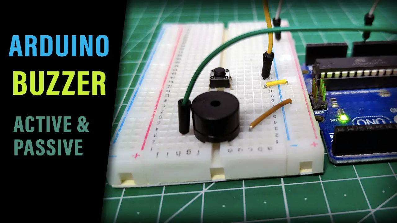
In this tutorial, we’ll learn how to use the Arduino With Active Buzzer & Passive Buzzer in your projects. You’ll also learn how to use the tone() and noTone() functions to create a couple of Arduino Buzzer Code Example projects.
We’ll start off by explaining the differences between Active Buzzers vs Passive Buzzers. Then, we’ll discuss how to interface each of them with Arduino with a couple of code examples to practice what we’ll learn. Without further ado, let’s jump right into it!
Table of Contents
- Piezo Buzzer (Speaker)
- Active Buzzers & Passive Buzzers
- Arduino Active Buzzer Interfacing
- Arduino Active Buzzer Code Example
- Arduino Passive Buzzer Interfacing
- Arduino Passive Buzzer Code Example
- Wrap Up
Piezo Buzzer (Speaker)
Piezo buzzers are a type of audio transducer that can be used to generate sound. They are a popular choice for simple sound effects, alarms, and tone-generation applications due to their small size, low cost, and ease of use. Here is an interactive tool that you can play with to experience what a buzzer sounds like!
A piezo buzzer is a polarized electronic device which means it has a positive lead & a negative lead. And it needs a voltage of 3.3v up to 12v to work, the working voltage is stated on the manufacturer page so make sure you get a 5v buzzer which is going to work just as fine with all microcontrollers.
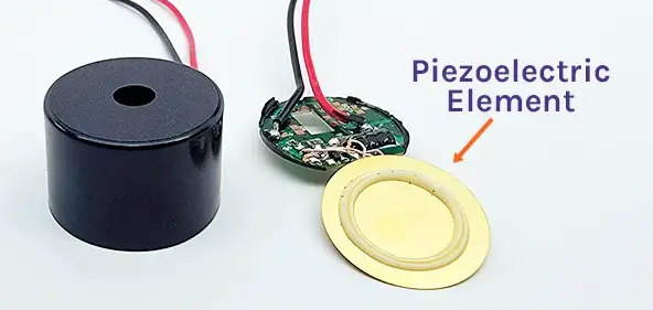
Applying voltage to the piezo buzzer terminals will cause a slight deformation in the piezo disc and by changing this voltage the piezo disc will vibrate and produce the buzzer sound we all know. This is called a Passive Buzzer.
Another type of buzzer doesn’t need a varying voltage, you just give it constant voltage and it has an internal chopper (oscillator) circuit that turns the constant voltage to a square wave and feeds that to the piezo disc to generate a fixed-frequency tone. And that type is called Active Buzzer.
Active Buzzers & Passive Buzzers
Active Buzzers are the easiest to use, as they have internal oscillators. You only need to feed it with constant voltage and it’ll play a continuous buzzer tone until you drive it LOW. It acts like a digital output device (like an LED or something) that you either turn ON or OFF.
Passive Buzzers on the other hand need an AC voltage signal in order to vibrate and make sound. Therefore, it’s a little bit harder to control compared to Active buzzers. But it also allows us to generate whatever note frequency we want to play.
Here is how you can easily differentiate between an Active buzzer and a passive buzzer:
1- By looking at the back of the buzzer
Passive Buzzers don’t “usually” have a backside cover, unlike the Active buzzers. This can ease your task of identifying an Active buzzer from a passive buzzer. However, it’s not guaranteed to always look like this and that’s why we need another test to make sure that what we think is an Active buzzer is actually correct.
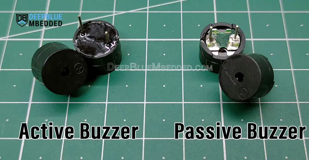
2- By connecting the buzzer to a 5v DC supply
By connecting the buzzer to a +5v DC supply, we can easily identify the Active buzzer from the passive buzzer. Because both of them have a different response to a constant +5v DC voltage, and it goes like this:
- Active Buzzer: will generate a continuous tone of buzzing sound until you disconnect the DC voltage supply.
- Passive Buzzer: will do a “click” sound (like a relay) the moment you apply DC voltage to it. Disconnect the voltage source and reconnect it again to hear the clicking sound again.
Passive buzzers will draw significantly more current compared to active buzzers when your supply them with a DC voltage source. Make sure you’re connected to a current limited source (set the limit to 50mA). Alternatively, you can use a 100Ω series resistor for current limiting to stay on the safe side.
This tutorial will provide you with more in-depth information about the differences between Active Buzzers & Passive Buzzers and the technical specs and construction for each type.
Arduino Active Buzzer Interfacing
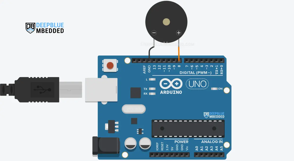
You only need a couple of jumper wires to hook up the buzzer to your Arduino board. Pay attention to the polarity of the buzzer terminals and connect the positive lead to any Arduino IO pins you’d like to use.
The Active buzzer needs a HIGH signal to start generating its fixed-frequency tone. And you don’t need to have a PWM output on that pin nor use the tone() function or anything else.
This code snippet below plays the Active buzzer tone for 1 second and turns it OFF afterward.
|
1 2 3 4 5 |
#define BUZZER_PIN 8 digitalWrite(BUZZER_PIN, HIGH); delay(1000); digitalWrite(BUZZER_PIN, LOW); |
Arduino Active Buzzer Code Example
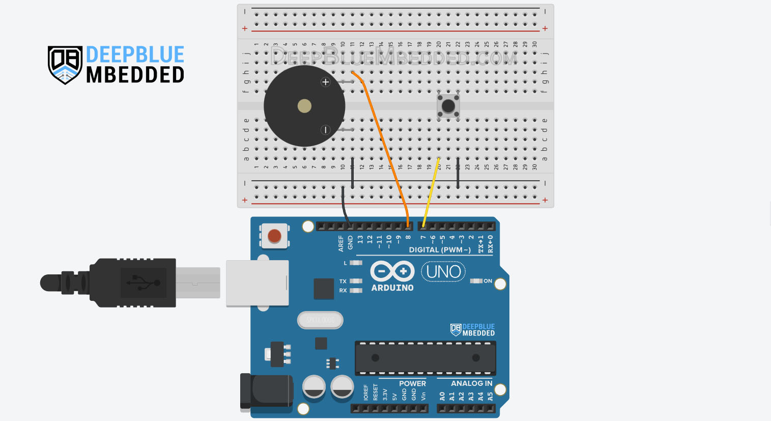
In this example project, we’ll interface an Active Buzzer with Arduino. We’ll control the buzzer using a push button, as long as the button is pressed, the buzzer will keep making sound. And it’ll go OFF whenever the button is released.
We can use any digital IO pins for this example, no PWM is needed to control an Active Buzzer with Arduino.
Wiring
Here is the wiring diagram for this example.
Code Example
Here is the full code listing for this example.
|
1 2 3 4 5 6 7 8 9 10 11 12 13 14 15 16 17 18 19 20 21 22 23 |
/* * LAB Name: Arduino (Active Buzzer) Example * Author: Khaled Magdy * For More Info Visit: www.DeepBlueMbedded.com */ #define BUZZER_PIN 8 #define BTN_PIN 7 void setup() { pinMode(BUZZER_PIN, OUTPUT); pinMode(BTN_PIN, INPUT_PULLUP); } void loop() { if(digitalRead(BTN_PIN)) { digitalWrite(BUZZER_PIN, LOW); } else { digitalWrite(BUZZER_PIN, HIGH); } } |
Code Explanation
First of all, we’ll define the pins needed for the input push button and the buzzer output.
|
1 2 |
#define BUZZER_PIN 8 #define BTN_PIN 7 |
setup()
in the setup() function, we’ll set the pinMode to be output for the buzzer pin and INPUT_PULLUP for the push button.
|
1 2 |
pinMode(BUZZER_PIN, OUTPUT); pinMode(BTN_PIN, INPUT_PULLUP); |
loop()
in the loop() function, we’ll continuously read the input push button using the digitalRead() function. If the button is pressed (state == LOW), we’ll activate the buzzer output pin (Set it to HIGH). Otherwise, we’ll set it LOW.
|
1 2 3 4 5 6 7 8 |
if(digitalRead(BTN_PIN)) { digitalWrite(BUZZER_PIN, LOW); } else { digitalWrite(BUZZER_PIN, HIGH); } |
TinkerCAD Simulation
You can check this simulation project on TinkerCAD using this link.
Testing Results
Another Code Example
This is another code example that turns the Active buzzer ON and OFF as well but it also attempts to control the volume of the buzzer by hooking it up to a PWM (pin9) and changing the duty cycle value.
|
1 2 3 4 5 6 7 8 9 10 11 12 13 14 15 16 17 18 19 20 21 22 23 24 25 |
/* * LAB Name: Arduino (Active Buzzer) Example * Author: Khaled Magdy * For More Info Visit: www.DeepBlueMbedded.com */ #define BUZZER_PIN 9 #define BTN_PIN 7 void setup() { pinMode(BUZZER_PIN, OUTPUT); pinMode(BTN_PIN, INPUT_PULLUP); } void loop() { if(digitalRead(BTN_PIN)) { analogWrite(BUZZER_PIN, 0); } else { analogWrite(BUZZER_PIN, 127); } } |
It does indeed control the volume level of the buzzer but it also distorts the buzzer sound which is not meant to be connected to a PWM signal in the first place. But it’s still a thing and I thought you should know about it and try it by yourself.
Arduino Passive Buzzer Interfacing
The Passive Buzzer connection to the Arduino is exactly the same as what we’ve done with the Active Buzzer. We can use a PWM output pin to control the passive buzzer tone output. Or, alternatively, we can use any digital IO pin alongside the tone() and noTone() functions to control the passive buzzer device.
In software, we need to generate the AC signal required to drive the passive buzzer using the tone() function for example. We’ll be using it to set different output frequencies in the following code example in the next section.
Arduino tone() Function
Generates a square wave of the specified frequency (and 50% duty cycle) on a pin. A duration can be specified, otherwise, the wave continues until a call to the noTone() function. The pin can be connected to a piezo buzzer or another speaker to play tones.
Only one tone can be generated at a time. If a tone is already playing on a different pin, the call to tone() will have no effect. If the tone is playing on the same pin, the call will set its frequency.
Syntax
|
1 2 |
tone(pin, frequency); tone(pin, frequency, duration); |
Parameters
pin: the Arduino pin on which to generate the tone.
frequency: the frequency of the tone in hertz. Allowed data types:
unsigned int.
duration: the duration of the tone in milliseconds (optional). Allowed data types:
unsigned long.
If you want to play different pitches on multiple pins, you need to call noTone() on one pin before calling tone() on the next pin. Use of the tone() function will interfere with PWM output on pins 3 and 11 (on boards other than the Mega). It is not possible to generate tones lower than 31Hz using the tone() function.
Arduino Passive Buzzer Code Example
In this example project, we’ll interface a Passive Buzzer with Arduino. We’ll use it to play different frequency tones using a push button input. Every time the button is pressed we’ll play a different frequency tone using the tone() function. And we’ll turn it OFF using the noTone() function when the button is released.
Code Example
Here is the full code listing for this example.
|
1 2 3 4 5 6 7 8 9 10 11 12 13 14 15 16 17 18 19 20 21 22 23 24 25 26 27 28 29 30 31 |
/* * LAB Name: Arduino (Passive Buzzer) Example * Author: Khaled Magdy * For More Info Visit: www.DeepBlueMbedded.com */ #define BUZZER_PIN 8 #define BTN_PIN 7 int FrequencyArr[5] = {150, 350, 550, 750, 950}; int Idx = 0; void setup() { pinMode(BUZZER_PIN, OUTPUT); pinMode(BTN_PIN, INPUT_PULLUP); } void loop() { if(digitalRead(BTN_PIN)) { noTone(BUZZER_PIN); } else { tone(BUZZER_PIN, FrequencyArr[Idx++]); delay(500); if(Idx == 5) { Idx = 0; } } } |
Code Explanation
First of all, we’ll define the pins needed for the input push button and the buzzer output.
|
1 2 |
#define BUZZER_PIN 8 #define BTN_PIN 7 |
We’ll also define an array of frequencies that we’ll play one by one, each time the button is pressed. And we’ll also define an index ( Idx) variable to keep track of the note to be played.
|
1 2 |
int FrequencyArr[5] = {150, 350, 550, 750, 950}; int Idx = 0; |
setup()
in the setup() function, we’ll set the pinMode to be output for the buzzer pin and INPUT_PULLUP for the push button.
|
1 2 |
pinMode(BUZZER_PIN, OUTPUT); pinMode(BTN_PIN, INPUT_PULLUP); |
loop()
in the loop() function, we’ll continuously read the input push button using the digitalRead() function. If the button is pressed (state == LOW), we’ll play the note from the frequencies array to the buzzer output pin using the tone(pin, frequency) function. Otherwise, we’ll call noTone(pin) to turn the buzzer OFF.
When the frequency array reaches the last index, we reset it back to zero to start from the beginning of the array the next time the button is pressed.
|
1 2 3 4 5 6 7 8 9 10 11 12 13 |
if(digitalRead(BTN_PIN)) { noTone(BUZZER_PIN); } else { tone(BUZZER_PIN, FrequencyArr[Idx++]); delay(500); if(Idx == 5) { Idx = 0; } } |
TinkerCAD Simulation
You can check this simulation project on TinkerCAD using this link.
Testing Results
Parts List
Here is the full components list for all parts that you’d need in order to perform the practical LABs mentioned here in this article and for the whole Arduino Programming series of tutorials found here on DeepBlueMbedded. Please, note that those are affiliate links and we’ll receive a small commission on your purchase at no additional cost to you, and it’d definitely support our work.
Download Attachments
You can download all attachment files for this Article/Tutorial (project files, schematics, code, etc..) using the link below. Please consider supporting my work through the various support options listed in the link down below. Every small donation helps to keep this website up and running and ultimately supports our community.
Wrap Up
To conclude this tutorial, we can say that it’s not that hard to differentiate between Active & Passive Buzzers. We’ve managed to interface both buzzer types with Arduino and write some code to control each of them. If you need a beep sound with no requirement for frequency, you should pick the Active Piezo Buzzer.
But if you need to generate variable frequency notes, you should definitely choose the Passive Piezo Buzzer. Which will allow you to control the output audio frequency as per your project requirements.
If you’re just getting started with Arduino, you need to check out the Arduino Getting Started [Ultimate Guide] here.
And follow this Arduino Series of Tutorials to learn more about Arduino Programming.
This is the ultimate guide for getting started with Arduino for beginners. It’ll help you learn the Arduino fundamentals for Hardware & Software and understand the basics required to accelerate your learning journey with Arduino Programming.
FAQ & Answers
A buzzer in an Arduino project is an audio output electronic device. It’s made of a piezoelectric element that vibrates when we apply a varying voltage to it. We usually use buzzers in Arduino projects to make sound effects for the end users (like alarms, UI interfaces, smart gadgets, etc).
You can use an active buzzer to make a buzzer sound in Arduino. By applying a HIGH output to the Active Buzzer pin, it’ll generate a continuous beep sound until you drive the buzzer output pin LOW.
The Active buzzer needs a HIGH signal to start generating its fixed-frequency tone. And you don’t need to have a PWM output on that pin nor use the tone() function or anything else.
The Passive Buzzer needs an AC voltage signal in order to vibrate and make a sound. Therefore, we’ll need a PWM output pin to control a passive buzzer with Arduino. Or we can use the built-in tone() function to generate an audio tone with the desired frequency on the buzzer output pin.
There are two types of buzzers (Active and Passive).
Active Buzzers are the easiest to use, as they have internal oscillators. You only need to feed it with constant voltage and it’ll play a continuous buzzer tone until you drive it LOW. It acts like a digital output device (like an LED or something) that you either turn ON or OFF.
Passive Buzzers on the other hand need an AC voltage signal in order to vibrate and make sound. Therefore, it’s a little bit harder to control compared to Active buzzers. But it also allows us to generate whatever note frequency we want to play.
