In this tutorial, we’ll discuss Arduino I2C Communication from the very basic concepts all the way to implementing Arduino I2C-based serial communication. We’ll create a couple of Arduino I2C projects in this tutorial, the first of which will be Arduino with I2C LCD 16×2 interfacing. In the second project, we’ll do an I2C Communication Between Two Arduino Boards.
Without further ado, let’s get right into it!
Table of Contents
- Introduction To I2C Communication
- Arduino I2C Communication (TWI)
- Arduino Wire Library (I2C Library)
- Arduino I2C Programming
- Arduino I2C Communication Configurations
- I2C Communication Between Two Arduino Boards
- Arduino I2C Example – I2C LCD 16×2 Interfacing
- Remarks on Arduino I2C Communication
- Wrap Up
Introduction To I2C Communication
I2C, I2C, or IIC (Inter-Integrated Circuit) is a very popular serial communication protocol that’s widely used by different sensors and modules in embedded systems. It consists of 2 pins only (one for serial data and one for the serial clock). Hence the name, TWI (Two-Wire Interface).
The I2C is a multi-master multi-slave protocol that supports a large number of devices on the same 2-wire bus. Each device has a unique ID that others can use to directly address that specific device. And it’s considered the most efficient serial communication bus in terms of the number of IO pins needed to establish a communication network of multiple devices.
I2C Modes & Bus Speeds
The I2C Bus has five operating speed categories. Standard-mode, Fast-mode (Fm), Fast-mode Plus (Fm+), and High-speed mode (Hs-mode) devices are downward-compatible. This means any device may be operated at a lower bus speed category than its own. Ultra Fast-mode devices are not compatible with previous versions since the bus is unidirectional.
Bidirectional bus:
- Standard-Mode (Sm), with a bit rate up to 100 kbit/s
- Fast-Mode (Fm), with a bit rate up to 400 kbit/s
- Fast-Mode Plus (Fm+), with a bit rate up to 1 Mbit/s
- High-speed Mode (Hs-mode), with a bit rate up to 3.4 Mbit/s.
Unidirectional bus:
- Ultra Fast-Mode (UFm), with a bit rate of up to 5 Mbit/s
You have to refer to the specific device datasheet to check the typical details for the i2c hardware specifications that have actually been implemented on-chip. For example, the Arduino (Atmega328p) microcontroller supports up to the Fast-Mode (Fm) which has a data transfer rate up to 400 kHz.
I2C Physical Layer (Hardware)
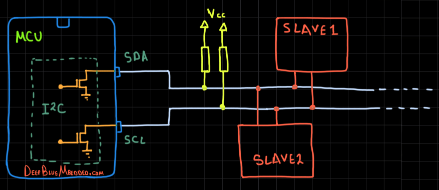
The I2C bus uses what’s known as an open-drain (or open-collector) output driver for both SDA and SCL lines. Which as the name suggests is having each IO pin connected to the collector of the output driver transistor internally, while having it pulled up to Vcc with a resistor eternally.
That’s why the default (IDLE) state for each line is HIGH when the open-drain driver is turned OFF. However, if we turn ON the output driver, the IO pin is driven LOW to the ground by the output driver transistor as you can see in the diagram below.
The I2C bus lines being “open-drain” bidirectional pins makes it perfect for multi-master multi-slave sort of communication without any risk of having collisions. And that’s due to having what’s called “Bus Arbitration” in case of multiple masters did initiate a transaction at the exact same time.
Anyone will write a 0 first while the other is writing a 1, will win the arbitration and continue its message and the other master will stop and wait till the end. That’s because of the nature of “Open-drain” output.
To write a 0, we turn ON the output driver to pull the signal line to LOW. To write a 1, we turn OFF the output driver and the line will be pulled up to HIGH by the effect of the external resistors. That’s why bus arbitration is a very powerful feature for I2C communication.
Elements of I2C Transactions
A typical I2C message consists of some basic elements (conditions) that take place on the I2C bus sequentially and it always starts with a start condition (s). Followed by the desired slave device address (7-Bits or 10-Bits), then a R/W bit to determine whether the master (who initiated the S condition for communication) wants to read or write to this slave having that address.
Then if the slave exists and works OK, it’ll acknowledge back to the master by sending an Acknowledge bit ACK otherwise, it’s considered a Negative Acknowledge NACK. Afterward, the byte of Data is sent, followed by an acknowledge from the slave. And finally, the master can terminate the communication by sending the Stop Condition (P) sequence.
We can summarize these conditions (elements) of I2C bus signaling as follows:
- Start Condition (S)
- Stop Condition (P)
- Repeated Start (Restart) Condition (Sr)
- Acknowledge ACK (A)
- Not Acknowledge NACK (~A)
- Address + R/W
- Data Byte
There are so many other topics and details about I2C serial communication protocol like clock synchronization, clock stretching, bus arbitration, device addressing & direction control, and many other topics. It’s pretty much a huge topic in fact.
But, this is more than enough for the scope of this tutorial. However, if you want to learn more about serial communication fundamentals, and its underlying hardware, and to go deeper into the topic, then you need to check out the tutorial linked below which is the ultimate I2C guide.

This article will give more in-depth information about serial communication fundamentals and I2C serial communication protocol and explains every aspect of it in great detail with code examples.
Arduino I2C Communication (TWI)
The Arduino (Atmega328p) microcontroller has an I2C communication peripheral that supports up to 400 kHz data rates. It can operate as a master or slave depending on your desired configurations. It’s compatible with the I2C protocol standard, so it provides all commonly known I2C functionalities.
Arduino I2C Pins
The Arduino UNO (Atmega328p) microcontroller has only one I2C module, which has 2 pins: (SDA and SCL) as shown below.

The I2C Pins (SDA and SCL) are the Arduino analog input pins A4 and A5 respectively. If you’re going to use the Arduino I2C communication, you’ll not be able to use those 2 pins as analog input channels for the ADC or whatever.
Here is a summarized table for I2C Pins in the most common Arduino boards.
| Arduino Board | I2C Pins |
|---|---|
| Arduino UNO, Nano, Pro Mini | A4 (SDA), A5 (SCL) |
| Arduino Mega | 20 (SDA), 21 (SCL) |
| Arduino Leonardo, Micro | 2 (SDA), 3 (SCL) |
Typically, you won’t need more than one I2C module on your Arduino microcontroller. Because if you need to add a new extra device to the I2C bus, it’s as simple as hooking it up to the SCL and SDA lines and you’re good to go. Unlike the UART which is a single master single slave communication port.
Arduino I2C Speed (Frequency)
The default Arduino I2C Speed is 100kHz and it can be increased up to a maximum of 400kHz as stated earlier.
The Arduino UNO (Atmega328p) microcontroller supports up to the I2C Fast-Mode (Fm) which has a data transfer rate up to 400 kHz.
Arduino I2C Pullup Resistor
The Arduino built-in Wire.h library for I2C communication enables the internal pullup resistors for both SDA & SCL lines. The internal pullup resistors (Rpu= 20~50kΩ) are pretty much weak and not sufficient. Therefore, you can manually disable them in code, and connect your external I2C pullup resistors.
The weak internal pullup resistors provide a drive current to the IO pin around (0.15mA) which is very low actually. This makes the I2C signals on both SDA & SCL lines a lot less sharp on both RISING and FALLING edges. This can be a serious issue if you want to increase the I2C communication speed. False edge detection will occur and corrupt the I2C messages.
We’re typically aiming for an IO pin drive current of around 1mA which means a 4.7kΩ resistor will do the job (5v/4.7kΩ ≈ 1mA). For maximum speed, you can increase the IO drive strength by setting the current to around 2mA. This can be achieved with 2.2kΩ pullup resistors.
The built-in I2C ( Wire) library enables the internal pullup resistors for both SDA & SCL lines. You can manually disable them and connect external pullup resistors for more reliable performance. Aim for an IO pin drive current (1~2mA), depending on the I2C bus VDD voltage (I = VDD / RPU).
Arduino I2C Voltage
After deciding on the proper value for the pullup resistors (RPU), we need to also decide on the VDD voltage that we’ll hook our I2C bus lines (SDA & SCL) up to. Normally, it’s 5v for the Arduino UNO. Arduino IO pins can tolerate up to 5.5v for any IO pin.
However, it also depends on the voltage level that the I2C slave device can tolerate. Some devices do only support a 3.3v logic level, so you need to hook up the I2C bus pins to 3.3v through the RPU resistors. The Arduino I2C peripheral will still perform normally at 3.3v despite the fact that it uses a 5v logic level.
You need to hook up the I2C pins (SDA & SCL) to 3.3v through the RPU resistors if your I2C slave device works with a 3.3v logic level and can’t tolerate 5v signals. The Arduino I2C will still work okay because the minimum input voltage that’s considered HIGH for the Arduino (Atmega328p) is 0.6VDD which is 0.6 x 5 = 3v. Therefore, the 3.3v I2C signals will still work just as fine.
Arduino I2C Applications
There are so many modules and sensors that we can interface with Arduino using the I2C bus, which include:
- RTC Clock
- OLED Display Screens
- I2C IO Pins Expander
- Temperature / Humidity Sensors
- External EEPROM Memory Chips
- MPU6050 IMU (Gyro+Accelerometer)
- and much more
To learn more about Arduino Serial Communication ports (protocols), we highly recommend that you check out the tutorial linked below. It’ll give you an overview of Arduino serial communication capabilities and a comparison between different serial communication ports. So you can make a guided design decision while picking communication protocols for your next projects.

This article will give more in-depth information about Arduino serial communication fundamentals and a general overview of Arduino’s UART, SPI, and I2C serial communication ports (protocol).
Arduino Wire Library (I2C Library)
To use Arduino’s I2C module, we’ll be using the built-in Wire library. This library handles all initialization and operations that you’d even need to perform with the I2C serial communication.
The Wire library implementation uses a 32-byte buffer, therefore any communication should be within this limit. Exceeding bytes in a single transmission will just be dropped.
There are both 7 and 8-bit versions of I2C addresses. 7 bits identify the device, and the eighth bit determines if it’s being written to or read from. The Wire library uses 7-bit addresses throughout. If you have a device datasheet or sample code that uses an 8-bit address, you’ll need to drop the LSB (shift the value one bit to the right), yielding an address between 0 and 127. However, the addresses from 0-7 are not usable because they are reserved by the I2C protocol so the first usable address is 8.
Wire Include
To be able to use the I2C Wire library, you need first to include it as shown below.
#include <Wire.h>
Arduino I2C Setup Functions (Wire Library)
Wire.begin()
First of all, you need to initialize the serial I2C module using the Wire.begin() function. It can initialize the I2C as a master device, or a slave device. For I2C slave initialization, you’ll need to specify the address you’d like to assign to yourself as an I2C slave on the bus. This is not needed for master I2C device initialization.
Wire.begin();     // Initialize As A Master I2C Device
Wire.begin(0x0A); // Initialize As A Slave I2C Device With Address = 0x0A
Valid I2C slave device address should be a 7-bit value that’s larger than 7 (e.g. 8, 10, …, 127).
Wire.end()
Disables the Wire library, reversing the effect of Wire.begin(). To use the Wire library again after this, call Wire.begin() again.
Wire.end()
This function can be helpful if you want to switch the I2C operation mode from master to slave or vice versa during runtime without restarting the whole microcontroller. This may be a rare condition, but it’s doable.
Wire.setClock()
This function modifies the clock frequency (data rate) for I2C communication. I2C peripheral devices have no minimum working clock frequency, however, 100KHz is usually the default value.
Wire.setClock(clockFrequency)
Parameters
clockFrequency: the value (in Hertz) of the desired communication clock. Accepted values are up to 100,000 (standard mode) and up to 400,000 (fast mode).
Arduino I2C Write Functions (Wire Library)
Wire.beginTransmission()
This function begins a transmission to the I2C peripheral device with the given address. Subsequently, queue bytes for transmission with the Wire.write() function and transmit them by calling Wire.endTransmission().
Wire.beginTransmission(address);
Parameters
address: the 7-bit address of the device to transmit to.
Wire.endTransmission()
This function ends a transmission to a peripheral device that was begun by Wire.beginTransmission() and transmits the bytes that were queued by write(). The Wire.endTransmission() accepts a boolean argument changing its behavior for compatibility with certain I2C devices.
If true, endTransmission() sends a stop condition after transmission, releasing the I2C bus. If false, endTransmission() sends a restart condition after transmission. The bus will not be released, which prevents another controller device from transmitting between messages. This allows one controller device to send multiple transmissions while in control. The default value is true.
You can use Wire.endTransmission() to end the I2C transaction on the bus or you can send to it a false like Wire.endTransmission(false) to send a restart condition on the I2C bus so the master device takes control on the I2C bus for another transaction process.
Wire.endTransmission();
Wire.endTransmission(stop);
Parameters
stop: true or false. True will send a stop message, releasing the bus after transmission. False will send a restart, keeping the connection active.
Returns
- 0: success.
- 1: data too long to fit in transmit buffer.
- 2: received NACK on transmit of address.
- 3: received NACK on transmit of data.
- 4: other error.
- 5: timeout
Wire.write()
This function writes data from a peripheral device in response to a request from a controller device or queues bytes for transmission from a controller to a peripheral device. This function is called between Wire.beginTransmission() and Wire.endTransmission().
You can use the Wire.write() function to send a single byte variable, a string of characters, or an array of bytes alongside the length of the array.
Wire.write(value);
Wire.write(string);
Wire.write(data, length);
Parameters
value: a value to send as a single byte.
string: a string to send as a series of bytes.
data: an array of data to send as bytes.
length: the number of bytes to transmit.
Returns
The number of bytes written (reading this number is optional).
Example
#include <Wire.h>

byte val = 0x55;

void setup() {
  Wire.begin();                // Initialize I2C (Master Mode: address is optional)
  Wire.beginTransmission(44);  // Transmit to device with address 44 (0x2C)
  Wire.write(val);             // Sends value byte
  Wire.endTransmission();      // Stop transmitting
}

void loop() {
  // Nothing To Be Done Here
}
Arduino I2C Read Functions (Wire Library)
Wire.requestFrom()
This function is used by the controller device to request bytes from a peripheral device. The bytes may then be retrieved with the Wire.available() and Wire.read() functions. The Wire.requestFrom() function takes a boolean argument that changes its behavior for compatibility with certain I2C devices.
If true, the requestFrom() function sends a stop condition on the I2C bus after the request, releasing the I2C bus. If false, the requestFrom() function sends a restart condition after the request. The bus will not be released, which prevents another master device from requesting between messages. This allows one master device to send multiple requests while in control. The default value is true.
Wire.requestFrom(address, quantity);
Wire.requestFrom(address, quantity, stop);
Parameters
address: the 7-bit slave address of the device to request bytes from.
quantity: the number of bytes to request.
stop: true or false. true will send a stop message after the request, releasing the bus. False will continually send a restart after the request, keeping the connection active.
Returns
byte: the number of bytes returned from the peripheral device.
Wire.available()
This function returns the number of bytes available for retrieval with read(). This function should be called on a controller device after a call to requestFrom() or on a peripheral device inside the onReceive() handler.
Wire.available();
Parameters
None.
Returns
The number of bytes available for reading.
Wire.read()
This function reads a byte that was transmitted from a peripheral device to a controller device after a call to requestFrom() or was transmitted from a controller device to a peripheral device.
Wire.read();
Parameters
None.
Returns
The next byte received.
Example
#include <Wire.h>

byte RxBuffer[100] = {0};
int RxIdx = 0;

void setup() {
  Wire.begin();  // Initialize I2C (Master Mode: address is optional)
}

void loop()
{
    Wire.requestFrom(0x55, 6);  // Request 6 bytes from slave device @ address 0x55
    // Slave may send less than requested
    while(Wire.available()) {
        RxBuffer[RxIdx++] = Wire.read();  // Receive a byte & push it into the RxBuffer
    }
    delay(100);
}
Arduino I2C Event Handler Functions (Wire Library)
Wire.onReceive()
This function registers a callback function to be called when a peripheral device receives a transmission from a controller device.
Wire.onReceive(handler);
Parameters
handler: the function to be called when the peripheral device receives data. This handler function should take a single int parameter (the number of bytes read from the controller device) and return nothing.
Returns
None.
Wire.onRequest()
This function registers a callback function to be called when a controller device requests data from a peripheral device.
Wire.onRequest(handler);
Parameters
handler: the function to be called, takes no parameters and returns nothing.
Returns
None.
You can also refer to Arduino’s official Wire Library documentation for more information.
Arduino I2C Programming
In this section, we’ll briefly summarize all the necessary steps that you need to follow in your code to implement I2C-based communication systems. First of all, we’ll discuss how to implement an I2C master device. Then, we’ll move to implement an I2C slave device. And finally, I’ll give you an I2C scanner code example that you can run to detect the addresses of I2C slave devices on the bus.
Keep in mind that both I2C master and slave devices have the ability to do both operations [ data transmission (Tx), data reception (Rx), or both of them simultaneously ]. It depends on your application and what you’re trying to achieve.
1. Arduino I2C Master Device
For an I2C Master device, you need to initialize the I2C module at first. And there is no need to specify an address for your I2C master device. Then, you’re able to do I2C transactions on the bus with any slave device.
For data transmission, you just start the I2C transaction and send your data to the slave device @ the specific address assigned to it. For data reception, the master device should send a requestFrom() the specified slave address.
I2C Master Tx Code Example
#include <Wire.h>

int AN_POT;

void setup() {
  Wire.begin(); // Initialize I2C (Master Mode: address is optional)
}

void loop() {
  AN_POT = analogRead(A0);
  Wire.beginTransmission(0x55); // Transmit to device with address 85 (0x55)
  Wire.write((AN_POT>>2));      // Sends Potentiometer Reading (8Bit)
  Wire.endTransmission();       // Stop transmitting
  delay(100);
}
I2C Master Rx Code Example
#include <Wire.h>

byte RxByte;

void setup() {
  Wire.begin(); // Initialize I2C (Master Mode: address is optional)
}

void loop() {
  Wire.requestFrom(0x55, 1); // Request From Slave @ 0x55, Data Length = 1Byte
  while(Wire.available()) {  // Read Received Datat From Slave Device
    RxByte = Wire.read();
  }
  delay(100);
}
2. Arduino I2C Slave Device
For an I2C Slave device, you need to initialize the I2C module first. And you also need to assign an address for your I2C slave device. Then, you’re able to do I2C transactions on the bus with any master device.
For data reception, you need to enable the onReceive event and add a handler function for it. In which you’ll be able to check available received data (if any) and read it. For data transmission, you need to enable the onRequest event and add a handler function for it.
If an I2C master device on the bus requested data that you (the I2C slave device) provide, then the onRequest event will trigger and in the handler function you can send the data using the Wire.write() function.
I2C Slave Rx Code Example
#include <Wire.h>

byte RxByte;

void I2C_RxHandler(int numBytes)
{
  while(Wire.available()) {  // Read Any Received Data
    RxByte = Wire.read();
  }
}

void setup() {
  Wire.begin(0x55); // Initialize I2C (Slave Mode: address=0x55 )
  Wire.onReceive(I2C_RxHandler);
}

void loop() {
  // Nothing To Be Done Here
}
I2C Slave Tx Code Example
#include <Wire.h>

byte TxByte = 0xAA;

void I2C_TxHandler(void)
{
  Wire.write(TxByte);
}

void setup() {
  Wire.begin(0x55); // Initialize I2C (Slave Mode: address=0x55 )
  Wire.onRequest(I2C_TxHandler);
}

void loop() {
  // Nothing To Be Done Here
}
To learn more about the Arduino I2C slave setup with multiple code examples & use cases, you definitely need to check out the tutorial below.

This tutorial will give you more in-depth information about how to set up your Arduino board as an I2C Slave device. And you’ll also get 3 project examples for setting up Arduino as an I2C Slave Receiver, I2C Slave Transmitter, and I2C Slave Receiver-Transmitter applications.
3. Arduino I2C Scanner
The I2C Scanner example is a very common Arduino sketch example to scan the I2C bus for available devices and get their addresses (if found). That can be useful if you don’t know the address of any I2C device or just not sure about it. Just run this example and get its addresses.
It can also tell if an I2C device is actually working or not. Maybe the device you’re trying to communicate with is actually damaged and no longer works. Then, it can be handy to run this example and make sure everything is OK.
To learn more about the Arduino I2C Scanner application, code examples, and testing, you need to check out the dedicated tutorial below.
")
This article will give you more in-depth information about the Arduino I2C Scanner application and how to use it to detect various I2C devices’ addresses.
Arduino I2C Communication Configurations
The flexibility of the I2C bus allows for different communication configurations that we’ll summarize in this section hereafter. There are mainly 4 I2C bus communication configurations depending on the number of Master & Slaved devices on the I2C bus in your application.
1. Single-Master Single-Slave
At least there should be a single master and single slave on the I2C bus, that is why this is the simplest form of I2C communication configuration. Both I2C master & slave devices are allowed to send or receive data depending on your target application needs.
For example, the below diagram shows an I2C bus with a single master (Arduino UNO board) and a single slave (MPU6050 IMU sensor). Normally, the I2C communication will be requested from the master to the slave to send sensor reading data. This means the master here is a receiver while the slave is the transmitter.

2. Single-Master Multi-Slave
Another configuration is the single-master multi-slave which is the most common among all. Because you’ll normally have multiple slave devices (modules & sensors) connected to your target microcontroller (I2C master device).
For example, the below diagram shows an I2C bus with a single master (Arduino UNO board) and 2 slaves (MPU6050 IMU sensor & I2C EEPROM). Normally, the I2C communication will be requested from master to slave1 to send sensor reading data. This means the master here is a receiver while the slave1 is the transmitter.
And the I2C communication between the master and slave2 will be both (transmitting & receiving) because the EEPROM is used for read/write operations. Therefore, the communication direction changes during the runtime of your application. The master will be (TxRx) and the slave2 will be also (RxTx).

3. Multi-Master Single-Slave
This is quite an uncommon configuration but still possible and used in many cases. Where you have multiple microcontrollers on the I2C bus and there is only 1 slave device that both masters communicate with to get or send some data.
For example, the below diagram shows an I2C bus with 2 masters (Arduino UNO board & STM32 Nucleo Board) and only 1 slave (I2C EEPROM). The I2C communication between the masters and slave1 will be both (transmitting & receiving) because the EEPROM is used for read/write operations. Therefore, the communication direction changes during the runtime of your application.
If carefully implemented, this can be a powerful application where different microcontrollers have access to a shared memory on the I2C bus. But it’s your responsibility to guarantee that none of them will invalidate the data in specific memory locations and it only access what it’s meant to. And of course, the I2C devices on the bus will do both (TxRx) operations during runtime.

4. Multi-Master Multi-Slave
And finally, the multi-master multi-slave configuration which, as the name suggests, includes multiple master devices and multiple slaves on the I2C bus.
For example, the below diagram shows an I2C bus with 2 masters (Arduino UNO board & STM32 Nucleo Board) and only 2 slaves (MPU6050 IMU Sensor & I2C EEPROM). Both masters can communicate with any slave device on the bus (one at a time). The I2C bus arbitration will prevent any data corruption on the bus if both masters attempted communication at the exact same time.

I2C Communication Between Two Arduino Boards
An I2C device (Master or Slave) can be a transmitter or a receiver and it’s up to you, the system designer & programmer, to decide whether a specific I2C device on the bus (Master or Slave) will be a data transmitter or receiver.
Given that we’re only considering Two Arduino boards (I2C devices), then it’s a one-to-one communication. In other words, the Two Arduino boards will form a Single-Master Single-Slave I2C bus.
Therefore, the I2C communication between the two Arduino boards can take one of the following forms:
- Master (Tx) → Slave (Rx)
- Master (Rx) ← Slave (Tx)
- Master (TxRx) ↔︎ Slave (RxTx)
Which depends on your target application and what you’re trying to achieve. This will be the basis on which you’ll choose the most suitable form of communication between the two Arduino boards (I2C devices).
Check out the tutorial below for a more in-depth demonstration and example application for each of the 3 communication forms mentioned above. And we’ll also discuss the use cases for each form of communication + when & why you should choose one over the others. You definitely need to check it out to establish I2C communication between two Arduino boards.

This article will give you more in-depth information about how to set up I2C communication between two Arduino boards. We’ll discuss all 3 possible communication configurations and implement them one by one through the tutorial. It’s highly recommended to check it out.
Arduino I2C Example – I2C LCD 16×2 Interfacing
Now, let’s test what we’ve learned so far about the Arduino I2C LCD and create our first project to display numeric variables to the I2C LCD display. We’ll create a counter variable and print it to the LCD using the .print() function.
Which can also accept a lot of variable data types (strings, integers, float, double, etc). So luckily, we won’t be in need to do string manipulations and data type conversion to achieve the goals of this example project.
Wiring
This is the wiring diagram for the I2C LCD with Arduino UNO.

Example Code
Here is the full code listing for this example.
/*
 * LAB Name: Arduino I2C LCD 16x2 Demo
 * Author: Khaled Magdy
 * For More Info Visit: www.DeepBlueMbedded.com
*/
#include <Wire.h>
#include <LiquidCrystal_I2C.h>

uint16_t Counter = 0;
LiquidCrystal_I2C MyLCD(0x27, 16, 2); // Creates I2C LCD Object With (Address=0x27, Cols=16, Rows=2)

void setup()
{
  MyLCD.init();
  MyLCD.backlight();
  MyLCD.setCursor(0, 0);
  MyLCD.print("Counter Value:");
}

void loop()
{
  MyLCD.setCursor(0, 1);
  MyLCD.print(Counter++);
  delay(250);
}
Code Explanation
First of all, we need to include the Arduino Wire.h library to use the I2C communication module, then the LiquidCrystal_I2C.h library which we’ll be using to control the I2C LCD module (PCF8574).
#include <Wire.h>
#include <LiquidCrystal.h>
Next, we’ll create an object of the LiquidCrystal_I2C class and define its parameters. The parameters for the LiquidCrystal_I2C object are the I2C device address (0x27), the number of LCD columns, and the number of LCD rows. Those are (16, 2) for 16×2 LCDs.
LiquidCrystal_I2C MyLCD(0x27, 16, 2); // Creates I2C LCD Object With (Address=0x27, Cols=16, Rows=2)
setup()
in the setup() function, we initialize the I2C LCD object ( MyLCD) using the .init() function. We also activate the LCD’s backlight by using the .backlight() function.
MyLCD.init();
MyLCD.backlight();
Then, we set the LCD cursor position to point to the first line, the first character cell. Any write operation to the LCD will start from the current cursor position value, that’s why it’s important to set it manually before attempting any write operation. To make sure that the text will be displayed exactly where we want it to be.
MyLCD.setCursor(0, 0); // (CharIndex, LineIndex)
Next, we’ll print the first text message "Counter Value:" to the LCD starting from the current cursor position (0, 0). Using the .print() function.
MyLCD.print("Counter Value:");
loop()
in the loop() function, we’ll point to the first character location on the second row (line) of the LCD. And write the Counter variable to the LCD using the .print() function.
MyLCD.print(Counter++);
We also increment the Counter variable and insert a small time delay before repeating the same instructions over and over again.
Simulation
Here is the simulation result for this project on the TinkerCAD simulator.
You can check this simulation project on TinkerCAD using this link.
Testing Results
Here is the result of testing this project code example on my Arduino UNO board.
It’s highly recommended to check out the Arduino I2C LCD interfacing tutorial linked below for more information about the I2C LCD module and how to use it with Arduino. There are so many examples right there which will definitely help you get the hang of it.

This is the ultimate guide for Arduino I2C LCD interfacing. Check it out to learn how the I2C LCD module works, how to use the LiquidCrystal_I2C library function to control it, change the I2C device address, connect multiple LCDs with Arduino using only 2 pins, and much more.
Remarks on Arduino I2C Communication
Before concluding this tutorial, here are some good remarks for Arduino I2C communication that you need to keep in mind.
Arduino I2C Device Address Limitations
No multiple devices are allowed to have the exact same I2C address on the bus. Usually, manufacturers give you, the designer, a couple of IO pins to set the address of that I2C device (like an LCD, EEPROM, or RTC). So that you can have multiple units of the same device on the same I2C bus.
To further investigate this matter and provide some solution, let’s first define a problem statement and start searching for a convenient solution. Here is an I2C LCD (IO expander) called PCF8574. Its default address in the datasheet is 0x27 with all solder bridges open.

What if we’d like to hook up 3 units of I2C LCD on the exact same bus and control those LCDs with our Arduino board? What can we do to make this happen? Here are the proposed solution one by one (ordered by my personal preference)
1- Change The I2C Device Address
The first thing you should consider is to take advantage of the 3 bits of address available to you in the form of solder bridges. By mixing 0’s and 1’s, you’ll end up having 8 different unique addresses for 8 x I2C LCD units all working on the exact same bus.
We want just 3, so it’s more than enough. Let’s now change the problem statement, and let’s say we need to have 10 x I2C LCD units on the exact same I2C bus. What to do?
2- Use Arduino I2C Multiplexer (Expander)
Next, we can consider getting an I2C expander IC like (TCA9548A). It’s a very cheap solution to give some virtual addresses to identical I2C devices so that you become able of addressing each device on the bus with a unique address.
Here is a simplified diagram for this I2C expander chip. Note that it has its own I2C address and you can have multiple units of this expander IC so it does increase the addressable device significantly at a very low cost.

3- Use Arduino Software I2C (Bit-Banging)
One last solution that I don’t usually recommend is by using “Bit-Banging”. Actually, most serial communication protocols can be Bit-Banged by a microcontroller. It’s a software-emulated version that uses normal GPIO pins to simulate the I2C signaling on the bus.
It acts as if it’s a hardware I2C that’s generating the signals, but in reality, it’s the CPU doing all of this with certain timing constraints and is vulnerable to all sorts of errors and issues. But it’s still doable and being used under certain circumstances.
Parts List
Here is the full components list for all parts that you’d need in order to perform the practical LABs mentioned here in this article and for the whole Arduino Programming series of tutorials found here on DeepBlueMbedded. Please, note that those are affiliate links and we’ll receive a small commission on your purchase at no additional cost to you, and it’d definitely support our work.
Download Attachments
You can download all attachment files for this Article/Tutorial (project files, schematics, code, etc..) using the link below. Please consider supporting my work through the various support options listed in the link down below. Every small donation helps to keep this website up and running and ultimately supports our community.
Wrap Up
To conclude this tutorial, we’d like to highlight the fact that the Arduino I2C communication module is so powerful as it allows up to create a multi-master multi-slave communication bus using only 2 pins. There are so many communication configurations that we can achieve using the I2C protocol.
This tutorial is a fundamental part of our Arduino Series of Tutorials because we’ll build on top of it to interface various I2C sensors, modules, and displays with Arduino in other tutorials & projects.
If you’re just starting with Arduino, check out the Arduino Getting Started [Ultimate Guide] here.

This is the ultimate guide for getting started with Arduino for beginners. It’ll help you learn the Arduino fundamentals for Hardware & Software and understand the basics required to accelerate your learning journey with Arduino Programming.
This article will give more in-depth information about Arduino serial communication fundamentals and a general overview of Arduino’s UART, SPI, and I2C serial communication ports (protocol).
I am interested in knowing if I can communicate via an ESP32 TTGOT7 V1.3 Mini (Master) to an Makerfabs ESP32-S3 ILI9488 3.5in TFT Display (Slave) via I2c?
I currently have a pair of LoRa radios and ESP32 TTGOT7 V1.3 Minis passing their GPS coordinates to each other to calculate their respective distance between displayed on an 16X2 LCD Display.
I would like to add the Makerfabs ESP32-S3 ILI9488 3.5in Parallel TFT Display to fisually monitor our respectific positions on an off-line map on the display.
Can I expect this configuration of an ESP32 Master and an ESP32-S3 Slave configuration to be compatible?
Hi Paul, Sure you can. The I2C bus communication can help you achieve the task you’re asking about just like the 2x Arduino boards communication over I2C that I’ve demonstrated in this tutorial below (you can use the same code).
https://deepbluembedded.com/i2c-communication-between-two-arduino/
I hope it helps!
Kind regards,
Khaled M.