In this project, we’ll do a Serial Communication Between Two Arduino Boards. We’ll also discuss some Arduino UART basics and fundamentals as a quick review of what we’ve previously learned in more detail in this previous Arduino UART Tutorial. We’ll run the serial communication between two Arduino boards project in both the simulation environment and in real life to check how it behaves. Without further ado, let’s get right into it!
Table of Contents
- Arduino UART Serial Communication
- Serial Communication Between Two Arduino Boards (UART)
- Remarks on Serial Communication Between Two Arduino Boards
- Wrap Up
Arduino UART Serial Communication
UART (Universal Asynchronous Receiver-Transmitter) is the most popular serial communication protocol in embedded microcontrollers. In Arduino, we typically use the UART module for serial communication with the PC via a USB-TTL converter to print serial messages on the serial monitor.
There are actually two forms of UART Hardware as follows:
- UART – Universal Asynchronous Receiver/Transmitter
- USART – Universal Synchronous/Asynchronous Receiver/Transmitter
The Synchronous type of transmitter generates the data clock and sends it to the receiver which works accordingly in a synchronized manner. On the other hand, the Asynchronous type of transmitter generates the data clock internally. There is no incoming serial clock signal, so in order to achieve proper communication between the two ends, both of them must be using the same baud rate. The baud rate is the rate at which bits are being sent bps (bits per second).
Arduino UART Pins
The Arduino UNO has only one UART module which has two pins (RX for receiving serial data and TX for transmitting serial data). The UART pins’ mapping is as follows: RX is Arduino pin 0, and TX is Arduino pin 1 respectively.

Arduino UART Logic Level
Serial communication on pins TX/RX uses TTL logic levels (5V or 3.3V depending on the board). Don’t connect these pins directly to an RS232 serial port which operates at +/- 12V and can damage your Arduino board.
Arduino UART Parameters
When using UART (Universal Asynchronous Receiver Transmitter) communication on Arduino, several parameters can be configured to control the data transmission. These parameters determine aspects such as baud rate, data format, parity, and stop bits. Let’s explore each of these parameters.
Baud Rate
The baud rate specifies the speed at which data is transmitted over the UART interface. It represents the number of bits per second. Common baud rate options for Arduino include 9600, 115200, 57600, and 38400. Both the transmitting and receiving devices must be set to the same baud rate for successful communication.
Data Bits
Data bits determine the number of bits used to represent the data being transmitted. The most common configuration is 8 data bits, which allows the transmission of 8-bit data. However, Arduino also supports other options such as 5, 6, 7, or 9 data bits.
Parity Bit
Parity is an error-checking mechanism used to detect transmission errors. It adds an additional bit to each transmitted byte for error detection. The parity bit can be configured as even, odd, or none.
- Even – the parity bit is “1” if there is an odd number of 1’s in the data frame
- Odd – the parity bit is “0” if there is an even number of 1’s in the data frame.
Stop Bits
Stop bits indicate the end of a data frame. After transmitting the data bits, one or more stop bits are added to signal the completion of the transmission. The most common option is 1 stop bit, but 1.5 or 2-stop bits can also be used for specific applications.
Flow Control
Flow control manages the data flow between the transmitting and receiving devices to prevent data loss or buffer overflow. Two common flow control mechanisms are hardware flow control (using RTS/CTS signals) and software flow control (using XON/XOFF special characters).
It is important to configure the UART parameters correctly on both the transmitting and receiving devices to ensure proper communication. The Serial library in Arduino provides functions to set and read these parameters. By selecting the appropriate baud rate, data format, parity, and stop bits, you can establish reliable UART communication between Arduino boards and other devices.
If you need an extra UART module in your application, you can use the SoftwareSerial library which is a software-emulated UART module. It’ll bit-bang the UART serial pattern on any 2 pins of your choice. But note that it’ll cost you a lot of CPU load and it’s not going to be reliable at high speeds. Because at the end of the day, it’s not a real UART hardware module.

This article will give more in-depth information about Arduino serial communication fundamentals and a general overview of Arduino’s UART, SPI, and I2C serial communication ports (protocol).

This article will give more in-depth information about Arduino UART serial communication, how it works, and how to use the Arduino Serial library functions to send and receive data over the UART serial port and use it in a handful of practical projects & applications.
Serial Communication Between Two Arduino Boards (UART)
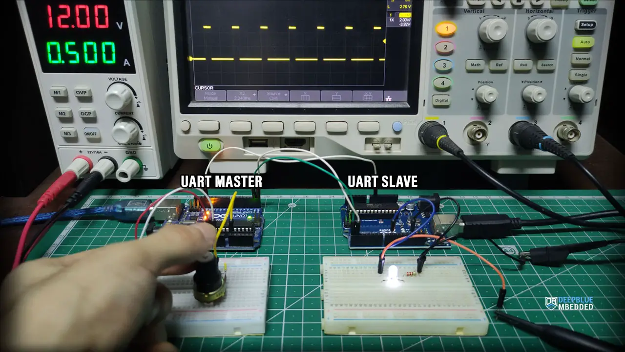
In this example project, we’ll establish serial communication between two Arduino Boards using UART serial communication. One Arduino board will act as a UART master that will read a potentiometer analog input and send it to the Slave Arduino UART device which is going to read the incoming data and use it to control a PWM output (LED).
This is a one-way communication between (Arduino UART Master) -> (Arduino UART Slave).
Wiring
Here is the wiring diagram for this example showing how to connect the LED output, and the potentiometer analog input on both Arduino boards (Master & Slave).

UART Master Code
Here is the full code listing for the Arduino UART Master Board.
/*
 * LAB Name: Arduino -> Arduino (UART Master)
 * Author: Khaled Magdy
 * For More Info Visit: www.DeepBlueMbedded.com
*/

void setup()
{
  Serial.begin(9600);
}

void loop()
{
  Serial.write(analogRead(A0)>>2);
  delay(100);
}
UART Slave Code
Here is the full code listing for the Arduino UART Slave Board.
/*
 * LAB Name: Arduino -> Arduino (UART Slave)
 * Author: Khaled Magdy
 * For More Info Visit: www.DeepBlueMbedded.com
*/
#define LED_PIN  9

uint8_t incomingByte = 0;

void setup()
{
  pinMode(LED_PIN, OUTPUT);
  Serial.begin(9600);
}

void loop()
{
  if(Serial.available())
  {
    incomingByte = Serial.read();
    analogWrite(LED_PIN, incomingByte);
  }
  delay(100);
}
Master Code Explanation
setup()
in the setup() function, we’ll initialize the UART serial port using the Serial.begin() function and set the baud rate to the default value (9600 bps).
Serial.begin(9600);
loop()
in the loop() function, we’ll read the analog input pin of the potentiometer (which is 10-Bit resolution 0- 1023) and convert it to 8-Bit resolution by dividing by 4 (or right-shifting twice “ >>2”). This is necessary because the UART serial communication sends the data byte-by-byte and the byte can have a value (0 up to 255).
And then we’ll send it over UART to the Arduino UART Slave board to control its PWM output duty cycle.
Serial.write(analogRead(A0)>>2);
Slave Code Explanation
We’ll first define a variable to hold the incoming byte of data via UART receive.
uint8_t incomingByte = 0;
setup()
in the setup() function, we’ll set the LED pinMode to be output. And we’ll initialize the UART serial port using the Serial.begin() function and set the baud rate to the default value (9600 bps).
pinMode(LED_PIN, OUTPUT);
Serial.begin(9600);
loop()
in the loop() function, we’ll check if there is any serial data has been received using the Serial.available() function. If data has been received, we’ll save it into the incomingByte variable and use it to control the LED PWM duty cycle using the analogWrite() function.
if(Serial.available())
{
    incomingByte = Serial.read();
    analogWrite(LED_PIN, incomingByte);
}
We can test this project’s code example using any available Arduino simulator environment. Here I’ll show you the simulation results for this project on both TinkerCAD and Proteus (ISIS).
TinkerCAD Simulation
You can check this simulation project on TinkerCAD using this link.
Proteus (ISIS) Simulation
Another extremely powerful simulation environment for Arduino is the Proteus (ISIS) with Arduino add-on library. It can definitely run our test projects for this tutorial. But you won’t feel its power until you need some virtual test equipment like an oscilloscope, function generator, power supply, and advanced SPICE simulation for auxiliary electronic circuitry that you may build around an Arduino microcontroller.
Here is the Arduino project simulation result from the Proteus environment.
Testing Results
Check out the tutorial below to help you get started with simulating your Arduino projects in the Proteus simulation environment.

This article will provide you with more in-depth information about using proteus ISIS for Arduino projects simulation.
Remarks on Serial Communication Between Two Arduino Boards
Before concluding this tutorial, here are some good remarks for Arduino UART communication that you need to keep in mind.
UART RX – TX
Always check the RX-TX connections if you’re facing issues getting the UART communication to work. This is the first and most common thing that people get wrong while working with UART. Double-check the wiring and make sure you’re connecting the RX of the first device to the TX of the second device and vice versa.
Common Ground Line
You also need to have a common ground connecting both devices that you’d like to establish UART communication between. They do need to have a common ground connection, otherwise, the data will get corrupted if it was sent & received at all.
Parts List
Here is the full components list for all parts that you’d need in order to perform the practical LABs mentioned here in this article and for the whole Arduino Programming series of tutorials found here on DeepBlueMbedded. Please, note that those are affiliate links and we’ll receive a small commission on your purchase at no additional cost to you, and it’d definitely support our work.
Download Attachments
You can download all attachment files for this Article/Tutorial (project files, schematics, code, etc..) using the link below. Please consider supporting my work through the various support options listed in the link down below. Every small donation helps to keep this website up and running and ultimately supports our community.
Wrap Up
To conclude this project, we’d like to highlight the fact that UART serial communication port is the easiest way to establish communication between two computer systems in a Master-Slave configuration. Another upside is that it can run flawlessly even if you extend the wires for a few extra meters, unlike other serial communication ports that are more sensitive. However, the major downside is that it’s a Master-Slave communication and we can’t add extra Arduino boards to the UART bus, only two devices (boards).
This tutorial is part of our Arduino Series of Tutorials that you should definitely check out and keep in your bookmarks in case you need to search for something or ask for help. I’ll gladly do my best to help you solve whatever issue you’re up against.
If you’re just getting started with Arduino, you need to check out the Arduino Getting Started [Ultimate Guide] here.

This is the ultimate guide for getting started with Arduino for beginners. It’ll help you learn the Arduino fundamentals for Hardware & Software and understand the basics required to accelerate your learning journey with Arduino Programming.