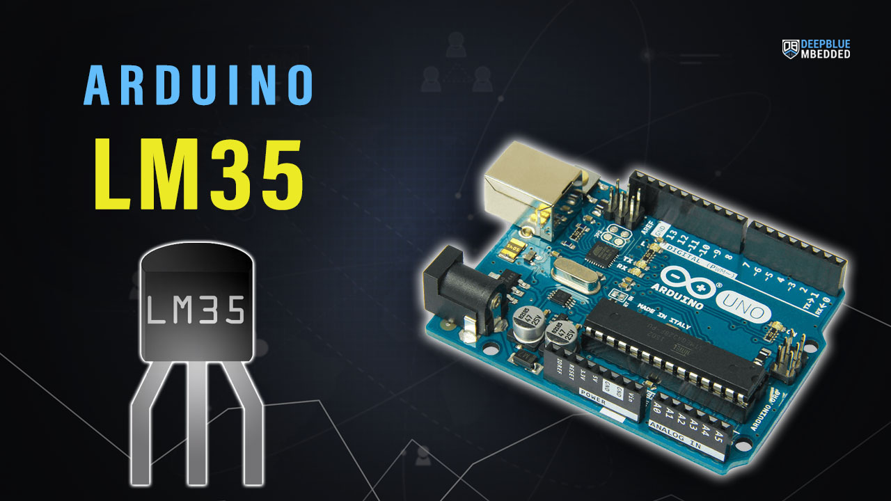
In this tutorial, you’ll learn how to interface Arduino with LM35 Temperature Sensor and use it to measure the surrounding temperature in degrees Celsius and Fahrenheit. We’ll create a couple of Arduino LM35 code example projects to practice what we’ll learn in this tutorial.
And we’ll also interface Arduino with LM35 and I2C LCD in this tutorial as well. Moreover, we’ll interface Multiple LM35 Temperature Sensors With Arduino and display the temperature readings independently in another project within this tutorial. Without further ado, let’s jump right into it!
Table of Contents
- Arduino LM35 Temperature Sensor
- Arduino LM35 Interfacing
- Arduino LM35 Code Example – Temperature Sensor
- Arduino LM35 LCD Example
- Arduino Multiple LM35 Temperature Sensors Example
- Wrap Up
Arduino LM35 Temperature Sensor
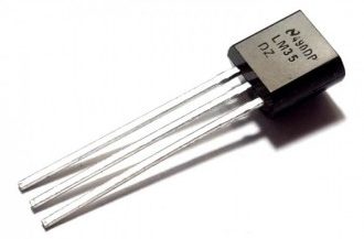
The LM35 is a temperature sensor widely used in electronic projects and midrange devices. It has limited usage in industrial applications due to maximum temperature range limitations. It’s rated to a full range of −55°C to 150°C.
You can power it up and instantly read the voltage level on the output terminal. The VOUT of the sensor directly maps to the sensor’s temperature as we’ll see hereafter.
LM35 Sensor Technical Specifications
- Linear + 10-mV/°C Scale Factor
- 0.5°C Ensured Accuracy (at 25°C)
- Rated for Full −55°C to 150°C Range
- Operates From 4 V to 30 V
- Less Than 60-μA Current Drain
- Non-Linearity Only ±¼°C Typical
LM35 Pinout
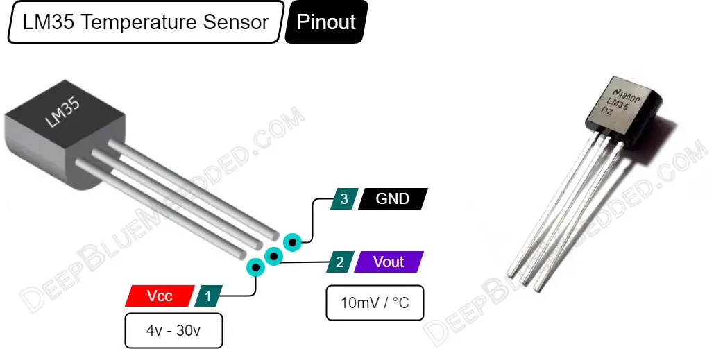
LM35 V-T Characteristics
As stated in the LM35 temperature sensor datasheet, the accuracy specifications of the LM35 are given with respect to a simple linear transfer function:
VOUT = (10 mv / °C) × T
where VOUT is the LM35 output voltage & T is the temperature in °C. And this is what we’ll be using in code in order to convert the ADC voltage readings to temperature values (in °C or °F).
You can play with the interactive tool below to see how the sensor’s analog output voltage changes when the temperature value is changed. And it’ll also show you the ADC digital value as captured (measured) by the Arduino code.
25 °C
0.25 v
128
At the maximum temperature (+150°C), the sensor’s output analog voltage will be almost 1.5v which is quite far from the Arduino’s ADC reference voltage (+5v). This means that most of the ADC’s range will stay unused and the voltage measurement resolution will be 5v/1024 = 5mv, which means we’ve got a temperature measurement resolution of 0.5°C.
The 0.5°C resolution is “luckily” equal to the sensor’s accuracy so we don’t need to enhance the measurement resolution by changing the ADC’s VREF voltage to a lower value because the voltage resolution increase will not improve the overall measurement resolution due to the sensor’s characteristic accuracy itself.
Arduino ADC (Analog Input)
The Arduino UNO has 6 analog input pins labeled from A0 to A5 as shown in the figure below. Those pins can be used with analog peripherals in the Arduino microcontroller such as ADC (A/D Converter) and the Analog Comparator.
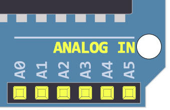
The Arduino ADC resolution is 10 bits, the digital output range is therefore from 0 up to 1023. And the analog input range is from 0v up to 5v (which is the default analog reference voltage VREF = +5v).
You can use the interactive tool below to set an analog input voltage and see the ADC digital output value that corresponds to the analog input voltage. The output equation for the ADC is as follows: ADC Output = ( Analog input voltage / VREF ) x (2n – 1). Where VREF = 5v and n is the ADC resolution which is 10bits.
It’s Highly Recommended to check out the tutorial below to learn more about Arduino ADC. It’s a prerequisite for this Arduino LM35 temperature sensor interfacing tutorial to help you understand the topic in more detail.
This tutorial is the ultimate guide for Arduino ADC & reading analog input voltages using the analogRead() function. You’ll learn, in-depth, everything about Arduino ADC, how it works, and how to make the best use of it with a lot of tips and tricks all the way through.
Arduino LM35 Interfacing
The LM35 sensor is a very popular temperature sensor that can easily be used with Arduino using the ADC analog input pin. It’s got a linear voltage output response with a slope of 10mv per °C. The typical LM35 temperature sensor’s operating range is (0°C To 150°C) but it can also measure negative temperatures down to -55°C below zero.
LM35 Temperature Sensor Configurations
You can connect your LM35 temperature sensor according to any of the following configurations (circuits) depending on your application and what you’re trying to achieve with it. It can normally measure positive temperatures (0°C To 150°C) with no extra components or circuitry.
And it can also measure negative temperatures down to -55°C and up to +150°C using the dual-supply configurations and an additional resistor. You’ll need, for example, a +5v power source, a -5v source, and a resistor R1 = 5v/50µA = 100kΩ.
If you need to measure negative temperatures with the LM35 sensor and don’t want to use dual-supply (positive & negative), you can still use the 3rd configuration shown below. It’ll require additional 2 diodes and 1 resistor (18kΩ). And you’ll also need 2 analog input pins to measure the differential voltage output of this configuration.
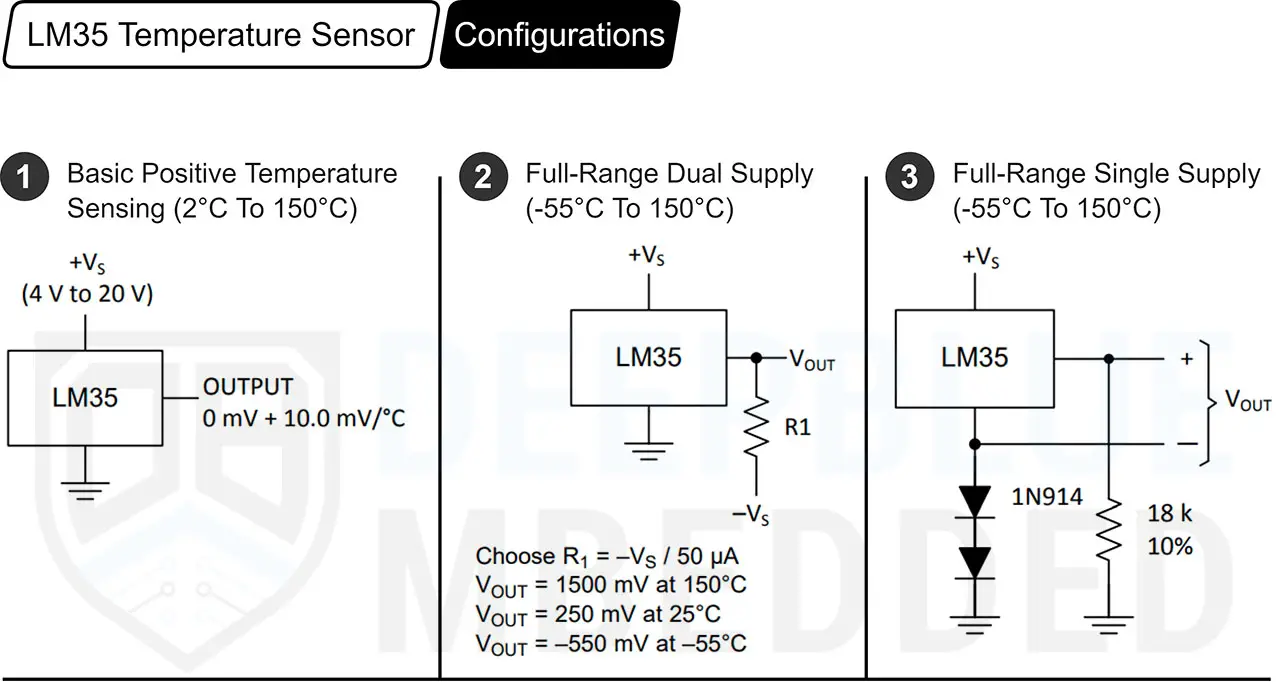
Arduino LM35 Wiring (Circuit Diagram)
Here is the wiring diagram for Arduino with the LM35 temperature sensor. Note that I’m using the basic LM35 configuration (positive temperature sensing).
And I’m using the A0 analog input pin to read the analog output voltage of the LM35 temperature sensor.
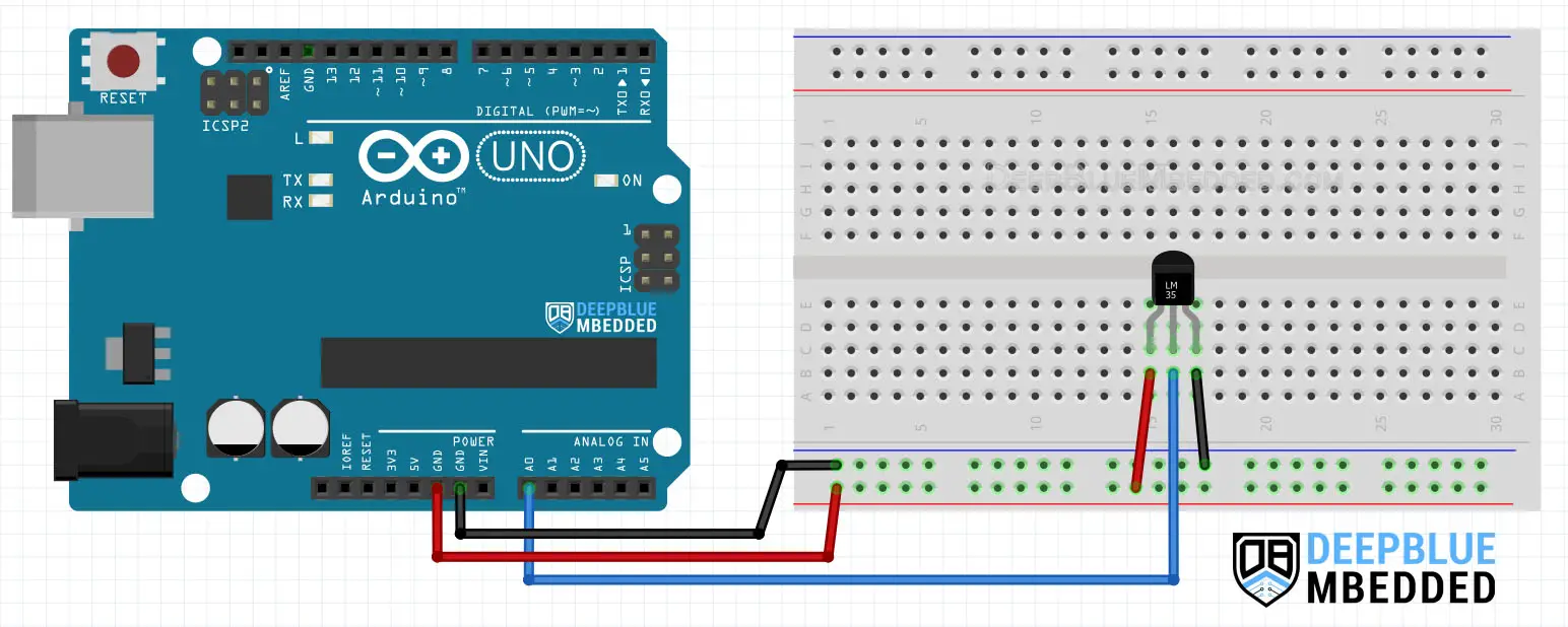
Arduino LM35 Code
Here is a test code example that reads the LM35 temperature sensor’s output on the A0 analog input pin and prints the temperature value to the serial monitor over UART. You can use it to check that your wiring and connections are all okay.
|
1 2 3 4 5 6 7 8 9 10 11 12 13 14 15 16 17 18 19 20 21 22 23 24 25 26 27 28 29 30 31 32 33 34 35 36 |
/* * LAB Name: Arduino LM35 Temperature Sensor Interfacing * Author: Khaled Magdy * For More Info Visit: www.DeepBlueMbedded.com */ #define LM35_PIN A0 int LM35_RawValue = 0; float Voltage_mV; float Temperature_C; float Temperature_F; void setup() { Serial.begin(9600); } void loop() { // Read LM35_Sensor ADC Pin LM35_RawValue = analogRead(LM35_PIN); Voltage_mV = ((LM35_RawValue*5.0)/1023.0) * 1000; // TempC = Voltage(mV) / 10 Temperature_C = Voltage_mV / 10; Temperature_F = (Temperature_C * 1.8) + 32; // Print The Readings Serial.print("Temperature = "); Serial.print(Temperature_C); Serial.print(" °C , "); Serial.print("Temperature = "); Serial.print(Temperature_F); Serial.println(" °F"); delay(100); } |
Arduino LM35 Code Example – Temperature Sensor
In this example project, we’ll use Arduino analog input with an LM35 temperature sensor to read the temperature value and print it over UART to the serial monitor in both units (degrees Celsius °C and Fahrenheit °F).
Code Example
Here is the complete code listing for this example.
|
1 2 3 4 5 6 7 8 9 10 11 12 13 14 15 16 17 18 19 20 21 22 23 24 25 26 27 28 29 30 31 32 33 34 35 36 |
/* * LAB Name: Arduino LM35 Temperature Sensor Interfacing * Author: Khaled Magdy * For More Info Visit: www.DeepBlueMbedded.com */ #define LM35_PIN A0 int LM35_RawValue = 0; float Voltage_mV; float Temperature_C; float Temperature_F; void setup() { Serial.begin(9600); } void loop() { // Read LM35_Sensor ADC Pin LM35_RawValue = analogRead(LM35_PIN); Voltage_mV = ((LM35_RawValue*5.0)/1023.0) * 1000; // TempC = Voltage(mV) / 10 Temperature_C = Voltage_mV / 10; Temperature_F = (Temperature_C * 1.8) + 32; // Print The Readings Serial.print("Temperature = "); Serial.print(Temperature_C); Serial.print(" °C , "); Serial.print("Temperature = "); Serial.print(Temperature_F); Serial.println(" °F"); delay(100); } |
Code Explanation
First, we define the IO pin used for the LM35 temperature sensor’s analog voltage reading. And we’ll also define some variables to be used during the voltage-to-temperature conversion process.
|
1 2 3 4 5 6 |
#define LM35_PIN A0 int LM35_RawValue = 0; float Voltage_mV; float Temperature_C; float Temperature_F; |
setup()
in the setup() function, we’ll initialize the UART serial port communication @ 9600bps baud rate.
|
1 |
Serial.begin(9600); |
loop()
in the loop() function, we’ll call the analogRead() function to get the voltage reading of the LM35 sensor. We’ll then convert it to voltage (in mv) and use that value to get the temperature in (°C and °F) units.
|
1 2 3 4 5 6 |
// Read LM35_Sensor ADC Pin LM35_RawValue = analogRead(LM35_PIN); Voltage_mV = ((LM35_RawValue*5.0)/1023.0) * 1000; // TempC = Voltage(mV) / 10 Temperature_C = Voltage_mV / 10; Temperature_F = (Temperature_C * 1.8) + 32; |
Then, we’ll just format the message string and send it over UART to be printed on the serial monitor at the PC side.
|
1 2 3 4 5 6 7 |
// Print The Readings Serial.print("Temperature = "); Serial.print(Temperature_C); Serial.print(" °C , "); Serial.print("Temperature = "); Serial.print(Temperature_F); Serial.println(" °F"); |
Proteus (ISIS) Simulation
Proteus (ISIS) is an extremely powerful simulation environment for Arduino. It can definitely run our test projects for this tutorial. But you won’t feel its power until you need some virtual test equipment like an oscilloscope, function generator, power supply, and advanced SPICE simulation for auxiliary electronic circuitry that you may build around an Arduino microcontroller.
Here is the Arduino project simulation result from the Proteus environment.
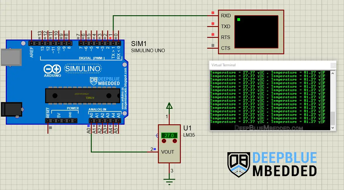
Check out the tutorial below to help you get started with simulating your Arduino projects in the Proteus simulation environment.
This article will provide you with more in-depth information about using proteus ISIS for Arduino projects simulation.
Testing Results
Arduino LM35 LCD Example
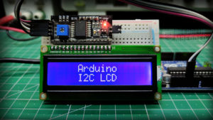
In this example project, we’ll use Arduino with an LM35 temperature sensor and I2C LCD 16×2 display to print out the temperature measurement. This example project will use the I2C LCD 16×2 with Arduino which you can learn more about by checking the tutorial linked below.
This is the ultimate guide for Arduino I2C LCD 16×2 interfacing and library functions explanation. It’ll guide you through everything you’d need to interface Arduino with an I2C LCD display.
Code Example
Here is the complete code listing for this example project.
|
1 2 3 4 5 6 7 8 9 10 11 12 13 14 15 16 17 18 19 20 21 22 23 24 25 26 27 28 29 30 31 32 33 34 35 36 37 38 |
/* * LAB Name: Arduino LM35 + I2C LCD 16x2 * Author: Khaled Magdy * For More Info Visit: www.DeepBlueMbedded.com */ #include <Wire.h> #include <LiquidCrystal_I2C.h> #define LM35_PIN A0 LiquidCrystal_I2C MyLCD(0x27, 16, 2); // Creates I2C LCD Object With (Address=0x27, Cols=16, Rows=2) int LM35_RawValue = 0; float Voltage_mV; float Temperature_C; void setup() { MyLCD.init(); MyLCD.backlight(); MyLCD.setCursor(0, 0); } void loop() { // Read LM35_Sensor ADC Pin LM35_RawValue = analogRead(LM35_PIN); Voltage_mV = ((LM35_RawValue*5.0)/1023.0) * 1000; // TempC = Voltage(mV) / 10 Temperature_C = Voltage_mV / 10; // Print Temperature Reading To The I2C LCD MyLCD.clear(); MyLCD.print("LM35 Thermometer"); MyLCD.setCursor(0, 1); MyLCD.print(Temperature_C); MyLCD.print(" C"); delay(100); } |
Code Explanation
First of all, we should include the Wire.h library for I2C communication and the LiquidCrystal_I2C.h library for the I2C LCD control.
|
1 2 |
#include <Wire.h> #include <LiquidCrystal_I2C.h> |
Then, we’ll define the analog input pin to be used for the LM35 sensor reading, we’ll create an instance of the I2C_LCD class, and define some variables to be used in the voltage-to-temperature measurement & conversion process.
|
1 2 3 4 5 6 7 |
#define LM35_PIN A0 LiquidCrystal_I2C MyLCD(0x27, 16, 2); // Creates I2C LCD Object With (Address=0x27, Cols=16, Rows=2) int LM35_RawValue = 0; float Voltage_mV; float Temperature_C; |
setup()
in the setup() function, we’ll initialize the I2C LCD display and turn ON its backlight.
|
1 2 3 |
MyLCD.init(); MyLCD.backlight(); MyLCD.setCursor(0, 0); |
loop()
in the loop() function, we’ll call the analogRead() function to get the voltage reading of the LM35 sensor. We’ll then convert it to voltage (in mv) and use that value to get the temperature in the (°C) unit.
|
1 2 3 4 5 |
// Read LM35_Sensor ADC Pin LM35_RawValue = analogRead(LM35_PIN); Voltage_mV = ((LM35_RawValue*5.0)/1023.0) * 1000; // TempC = Voltage(mV) / 10 Temperature_C = Voltage_mV / 10; |
Then, we’ll construct the string message that shows the resulting measured temperature and print it on the I2C LCD display.
|
1 2 3 4 5 6 |
// Print Temperature Reading To The I2C LCD MyLCD.clear(); MyLCD.print("LM35 Thermometer"); MyLCD.setCursor(0, 1); MyLCD.print(Temperature_C); MyLCD.print(" C"); |
Testing Results
Arduino Multiple LM35 Temperature Sensors Example
In this example project, we’ll use multiple LM35 temperature sensors with Arduino and I2C LCD display. We’ll take the temperature measurement from both sensors and display them separately on the I2C LCD display.
Code Example
Here is the complete code listing for this example.
|
1 2 3 4 5 6 7 8 9 10 11 12 13 14 15 16 17 18 19 20 21 22 23 24 25 26 27 28 29 30 31 32 33 34 35 36 37 38 39 40 41 42 43 44 45 46 47 48 49 50 51 |
/* * LAB Name: Arduino LM35 + I2C LCD 16x2 * Author: Khaled Magdy * For More Info Visit: www.DeepBlueMbedded.com */ #include <Wire.h> #include <LiquidCrystal_I2C.h> #define LM35_1_PIN A0 #define LM35_2_PIN A1 LiquidCrystal_I2C MyLCD(0x27, 16, 2); // Creates I2C LCD Object With (Address=0x27, Cols=16, Rows=2) int LM35_RawValue = 0; float Voltage_mV; float Temperature1_C; float Temperature2_C; void setup() { MyLCD.init(); MyLCD.backlight(); MyLCD.setCursor(0, 0); } void loop() { // Read LM35_Sensor1 ADC Pin LM35_RawValue = analogRead(LM35_1_PIN); Voltage_mV = ((LM35_RawValue*5.0)/1023.0) * 1000; // TempC = Voltage(mV) / 10 Temperature1_C = Voltage_mV / 10; // Read LM35_Sensor2 ADC Pin LM35_RawValue = analogRead(LM35_2_PIN); Voltage_mV = ((LM35_RawValue*5.0)/1023.0) * 1000; // TempC = Voltage(mV) / 10 Temperature2_C = Voltage_mV / 10; // Print Temperature Reading To The I2C LCD MyLCD.setCursor(0, 0); MyLCD.print("LM35_1 T= "); MyLCD.print(Temperature1_C); MyLCD.print("c"); MyLCD.setCursor(0, 1); MyLCD.print("LM35_2 T= "); MyLCD.print(Temperature2_C); MyLCD.print("c"); delay(100); } |
Code Explanation
First of all, we should include the Wire.h library for I2C communication and the LiquidCrystal_I2C.h library for the I2C LCD control.
|
1 2 |
#include <Wire.h> #include <LiquidCrystal_I2C.h> |
Then, we’ll define the 2 analog input pins to be used for the two LM35 sensors reading, we’ll create an instance of the I2C_LCD class, and define some variables to be used in the voltage-to-temperature measurement & conversion process.
|
1 2 3 4 5 6 7 8 9 |
#define LM35_1_PIN A0 #define LM35_2_PIN A1 LiquidCrystal_I2C MyLCD(0x27, 16, 2); // Creates I2C LCD Object With (Address=0x27, Cols=16, Rows=2) int LM35_RawValue = 0; float Voltage_mV; float Temperature1_C; float Temperature2_C; |
setup()
in the setup() function, we’ll initialize the I2C LCD display and turn ON its backlight.
|
1 2 3 |
MyLCD.init(); MyLCD.backlight(); MyLCD.setCursor(0, 0); |
loop()
in the loop() function, we’ll call the analogRead() function to get the voltage reading of the first LM35 sensor. We’ll then convert it to voltage (in mv) and use that value to get the temperature in the (°C) unit.
|
1 2 3 4 5 |
// Read LM35_Sensor1 ADC Pin LM35_RawValue = analogRead(LM35_1_PIN); Voltage_mV = ((LM35_RawValue*5.0)/1023.0) * 1000; // TempC = Voltage(mV) / 10 Temperature1_C = Voltage_mV / 10; |
We’ll do exactly the same logic to get the reading of the second LM35 temperature sensor.
|
1 2 3 4 5 |
// Read LM35_Sensor2 ADC Pin LM35_RawValue = analogRead(LM35_2_PIN); Voltage_mV = ((LM35_RawValue*5.0)/1023.0) * 1000; // TempC = Voltage(mV) / 10 Temperature2_C = Voltage_mV / 10; |
Then, we’ll construct the string message that shows the resulting measured temperatures from LM35 sensors 1 & 2. Then, we’ll print both temperature readings on the I2C LCD display.
|
1 2 3 4 5 6 7 8 9 |
// Print Temperature Reading To The I2C LCD MyLCD.setCursor(0, 0); MyLCD.print("LM35_1 T= "); MyLCD.print(Temperature1_C); MyLCD.print("c"); MyLCD.setCursor(0, 1); MyLCD.print("LM35_2 T= "); MyLCD.print(Temperature2_C); MyLCD.print("c"); |
Testing Results
Parts List
Here is the full components list for all parts that you’d need in order to perform the practical LABs mentioned here in this article and for the whole Arduino Programming series of tutorials found here on DeepBlueMbedded. Please, note that those are affiliate links and we’ll receive a small commission on your purchase at no additional cost to you, and it’d definitely support our work.
Download Attachments
You can download all attachment files for this Article/Tutorial (project files, schematics, code, etc..) using the link below. Please consider supporting my work through the various support options listed in the link down below. Every small donation helps to keep this website up and running and ultimately supports our community.
Wrap Up
To conclude this tutorial, we can say that you can easily interface Arduino with an LM35 temperature sensor to read the surrounding temperature and use that information for various Arduino projects. You can build on top of the examples provided here in this tutorial to create so many applications, you’re only limited by your imagination. Let me know if you have further questions or need help implementing your project.
If you’re just getting started with Arduino, you need to check out the Arduino Getting Started [Ultimate Guide] here.
And follow this Arduino Series of Tutorials to learn more about Arduino Programming.
This is the ultimate guide for getting started with Arduino for beginners. It’ll help you learn the Arduino fundamentals for Hardware & Software and understand the basics required to accelerate your learning journey with Arduino Programming.
