In this tutorial, we’ll discuss Arduino MOSFET Switch Circuit To Control Loads Like High-Power DC Motors & LEDs. You’ll learn how MOSFETs work, and how to interface Arduino With N-Channel IRF520 MOSFET Using PWM.
We’ll create an example project to Control The Speed of a DC Motor Using Arduino & IRF520 MOSFET, we’ll simulate and run the project code example to test its functionality. Without further ado, let’s get right into it!
Table of Contents
- Arduino MOSFET Interfacing
- Arduino MOSFET Switch Circuit (IRF520)
- Arduino MOSFET PWM Motor Control Example
- Selecting a MOSFET For Your Arduino Project
- Further Considerations After Selecting a MOSFET
- Arduino + Gate Driver = Happy MOSFET!
- Wrap Up
Arduino MOSFET Interfacing
The Arduino’s IO pins are able to source or sink up to 40mA of current per IO pin. This is the maximum absolute current that can be sourced from or sunk to any Arduino’s IO pin at any given time. All Arduino IO pins can source or sink up to 200mA combined at any given time.
As a rule of thumb, the Arduino IO pins are not capable of driving any sort of output load devices other than small LEDs, a buzzer, or any tiny device that requires a few mA of current to operate. Therefore, we typically use transistors with Arduino as output drivers for high-current load devices (such as Power LEDs, DC Motors, Stepper Motors, etc).
MOSFETs (Metal-Oxide-Semiconductor Field-Effect Transistors) are used as switches to control high-power load devices by allowing a small signal from the Arduino to charge the transistor’s gate to switch it ON, so it starts conducting and the load is powered ON. Discharging the MOSFET’s gate by driving it low, turns it OFF, and consequently, the load device also goes OFF.
There are two types of MOSFETs: N-Channel and P-Channel MOSFETs. In most cases, you can just go for an N-Channel device since it’s got a lower Rdson resistance which means it doesn’t heat up easily and is more power efficient than the P-Channel counterpart.
MOSFET Vs BJT
Control Mechanism: MOSFETs are controlled by voltage, while BJTs are controlled by current.
Switching Speed: MOSFETs generally have faster switching speeds compared to BJTs.
On-Resistance: MOSFETs typically have lower on-resistance (Rds(on)) than BJTs, resulting in less power loss and heat generation when driving loads.
Drive Voltage: MOSFETs require a higher gate voltage to turn on fully, especially high-power MOSFETs. This can sometimes necessitate additional gate driver circuits to achieve optimal performance.
All in all, for low-power load driver applications, you can use Arduino + BJT Transistor which is very easy to use. For high-power driver applications, it’s better to use MOSFET transistors with a discrete or integrated gate driver circuit as we’ll discuss in detail hereafter in this tutorial.
Arduino MOSFET Switch Circuit (IRF520)
Let’s say you’ll use an N-Channel MOSFET (IRF520) as a switch with your Arduino board to control some random load device (LED, Motor, or Heater). Here’s how to set it up and drive the MOSFET’s gate using a discrete BJT-based circuit.
Here are the specifications of the IRF520 MOSFET transistor as stated in its datasheet.
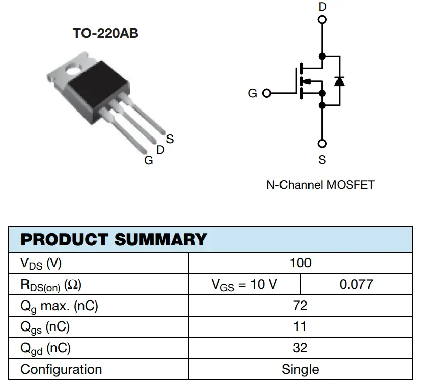
Arduino + IRF520 MOSFET
Here is the Arduino MOSFET (IRF520) circuit diagram.
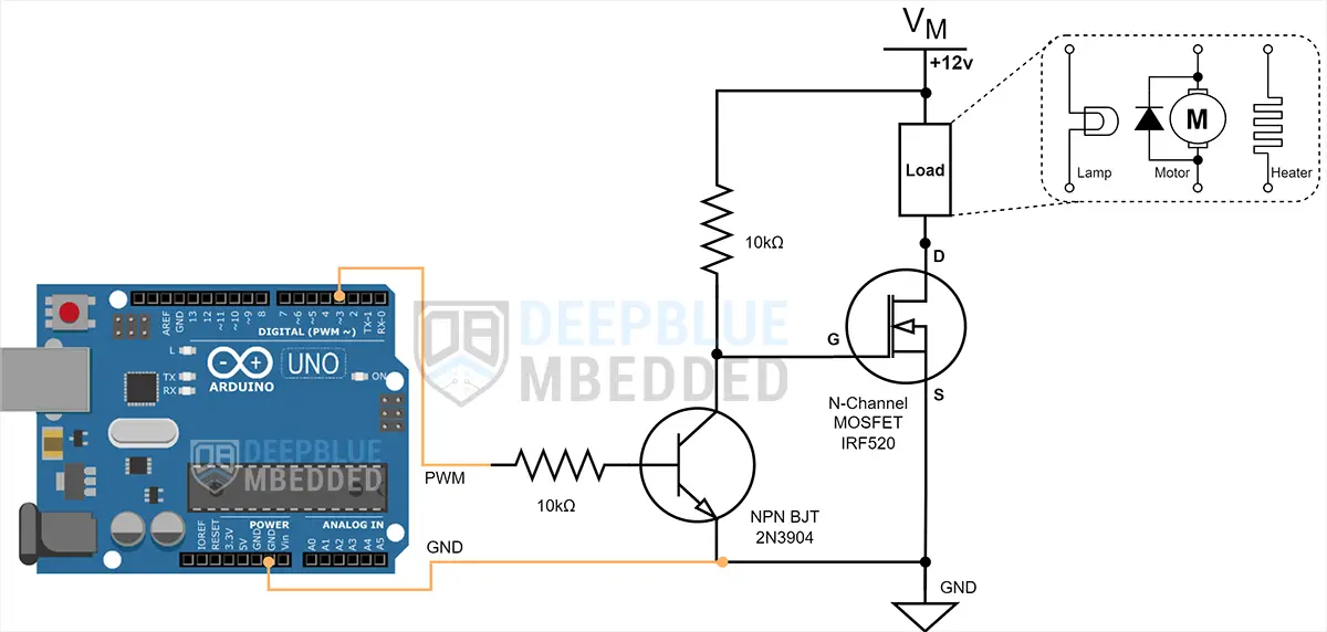
Note that in this circuit shown above, the MOSFET’s gate when driven HIGH is connected to the VMotor which is (+12v). The absolute maximum gate voltage for most of the MOSFETs is around +20v. Therefore, you may need to add a zener protection diode to the gate or use a gate driver IC instead of the method shown here.
Arduino MOSFET PWM Motor Control Example
In this example project, we’ll control a DC Motor’s speed with an Arduino PWM output pin + a MOSFET Transistor (IRF520). We’ll use a potentiometer and the analogRead() function to get the potentiometer reading and use it to control the PWM’s duty cycle and consequently the motor’s speed.
Arduino boards have several PWM output pins usually. Those pins are designated with a (~) mark next to the pin number on the board. Before discussing how to use the PWM output pins, let’s first define what is the PWM technique and what are the properties of a PWM signal.
Pulse Width Modulation (PWM) is a technique for generating a continuous HIGH/LOW alternating digital signal and programmatically controlling its pulse width and frequency. Certain loads like (LEDs, Motors, etc) will respond to the average voltage of the signal which gets higher as the PWM signal’s pulse width is increased.
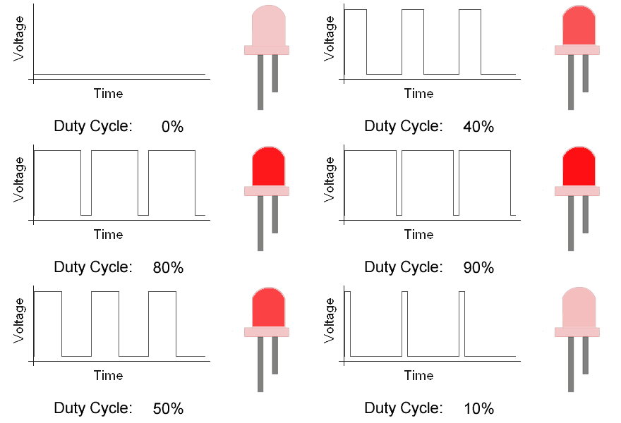
As you can see, the LED gets brighter as the pulse width (duty cycle) increases, and it gets dimmer as the pulse width decreases. And this is typically what we use the PWM output for.
Check the tutorial below to learn more about Arduino PWM. It’s a prerequisite for this project to help you understand the topic in more detail.
This tutorial will provide you with more in-depth information about Arduino PWM output. Starting from the basics of PWM signal, its frequency, duty cycle, and resolution, and will discuss in detail how it works and how to use it in various Arduino control projects.
Wiring
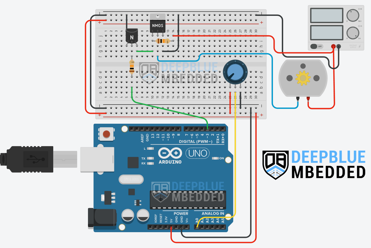
Here is the wiring diagram for this example showing how to connect the IRF520 MOSFET with the Arduino PWM output pin, the pre-driver BJT, the DC Motor, and the Battery. Pay attention to the common ground between the external power source (battery) and the Arduino board.
Example Code
Here is the full code listing for this example.
|
1 2 3 4 5 6 7 8 9 10 11 12 13 14 15 16 |
/* * LAB Name: Arduino PWM DC Motor Speed Control With IRF520 (N-Channel MOSFET) * Author: Khaled Magdy * For More Info Visit: www.DeepBlueMbedded.com */ #define MOTOR_PWM_PIN 3 void setup() { pinMode(MOTOR_PWM_PIN, OUTPUT); } void loop() { analogWrite(MOTOR_PWM_PIN, (analogRead(A0)>>2)); } |
Code Explanation
First of all, we define the IO pin used for the motor speed control output. It has to be a PWM-enabled IO pin (for UNO: 3, 5, 6, 9, 10, or 11).
|
1 |
#define MOTOR_PWM_PIN 3 |
setup()
in the setup() function, we’ll set the pinMode to be output.
|
1 |
pinMode(MOTOR_PWM_PIN, OUTPUT); |
loop()
in the loop() function, we’ll read the analog input pin of the potentiometer (which is 10-Bit resolution) and convert it to 8-Bit resolution by dividing by 4 (or right-shifting twice). Now, we’ve mapped the analog input value to the PWM duty cycle range.
Using the Arduino analogWrite() function, we’ll write back the ADC scaled reading as a duty cycle for the PWM to control the speed of the motor accordingly.
|
1 |
analogWrite(MOTOR_PWM_PIN, (analogRead(A0)>>2)); |
Simulation
Here is the simulation result for this project on the TinkerCAD simulator. Don’t pay much attention to the motor rotation animation, it may not be rendered in real-time or it’s spinning really fast so we can’t visually judge the motor speed. However, the RPM value and the DC current drawn from the power supply both correlate with the speed change.
You can check this simulation project on TinkerCAD using this link.
Testing Results
Here is the result of testing this project code example on my Arduino UNO board.
Selecting a MOSFET For Your Arduino Project
When choosing a MOSFET transistor for your Arduino project, several key parameters need to be considered to make sure it’s going to perform as expected. For example, here are the absolute maximum ratings for the IRF520 as stated in its datasheet.

VDS (Drain-Source Voltage)
This parameter indicates the maximum voltage that the MOSFET can withstand between the drain and source terminals. Ensure that the maximum VDS rating exceeds the highest voltage expected in your circuit to prevent damage to the MOSFET.
It’s advisable to leave a safety margin (for example: if you’re driving a +36v load, seek for a MOSFET with a VDS of 60v or more).
ID (Continuous Drain Current)
The ID rating specifies the maximum continuous current the MOSFET can handle. Choose a MOSFET with an ID rating higher than the maximum current your load may ever draw to avoid overheating and potential failure.
It’s advisable to leave a safety margin (for example: if you’re driving a 10A load, seek for a MOSFET with an ID of 20A or more).
RDS(on): Drain-Source On-Resistance
RDS(on) is the resistance between the drain and source terminals when the MOSFET is fully turned ON. A lower Rds(on) value results in less voltage drop and power dissipation across the MOSFET, making it more efficient.
It’s always better to get a MOSFET with as low RDS(on) value as possible, especially for high-current applications.
VGS(th): Logic Level MOSFETs
The Vgs(th) parameter indicates the minimum gate-to-source voltage required to start turning the MOSFET ON. For Arduino applications, you can search for logic-level MOSFETs which can be turned ON using only +5v.
Generally speaking, MOSFETs need (10v~12v) to fully turn ON. And those MOSFETs require a special gate driver circuit because your MCU (Arduino) only outputs a +5v signal.
For example: IRLZ44N is a Logic-Level MOSFET that you can use with Arduino without any complicated gate driver circuitry or whatever.
MOSFET Power Dissipation
Power dissipation represents the heat generated by the MOSFET during operation. This is calculated as the product of the current flowing through the MOSFET and the voltage drop across it [ P = VDS x ID ]. It can also be expressed as the equivalent turn-on resistance of the MOSFET multiplied by the current squared [ P = I2 x Rds(on) ].
Ensure that the MOSFET can dissipate the expected power without exceeding its thermal limits. A heatsink may be required for high-power applications.
Further Considerations After Selecting a MOSFET
There are some considerations that you may need to decide on after selecting a MOSFET device for your driver applications. Here we’ll discuss a few of those topics and you can make some good design decisions.
MOSFET Gate Resistor
You may find in MOSFET Drivers Circuits online that some of these include a small-value resistor (10Ω~100Ω) connected to the gate of the MOSFET transistor. This resistor slows down the charging of the gate capacitance so the transitions are not very sharp. This reduces the noise generated from the whole system and makes it more EMC-friendly.
It’s not mandatory if you don’t care about noise and such. But be careful if you’re going to add a resistor because if it’s larger than it should be, it’ll significantly slow down the MOSFET switching. The gate resistor (RG) and the MOSFET’s gate capacitance (CG) together form a low-pass filter with a time constant [ 𝜏 = RG x CG ]. This equation will help you calculate the needed resistor’s value to achieve a certain rise time.
Using Zener Diode For MOSFET’s Gate Protection
As stated earlier and as you’ve seen in the datasheet of the IRF520 MOSFET’s absolute maximum ratings, the gate voltage of the MOSFET (VGS) should never exceed ±20v. For this reason, some designers might incorporate a Zener diode in the circuit to protect the MOSFET against any change in the supply voltage.
There are better ways to go about this issue and protect your MOSFET’s gate, but using a zener diode is an easy fix despite being a non-optimal solution.
Add a Heatsink?
If you know that the load you’re doing to drive with your MOSFET transistor is a relatively light load, then you can just skip adding a heatsink to your MOSFET device. However, if you’re doing some serious work, then here is how to go about it!
To decide if your MOSFET will need a heatsink or not, you’ll need the thermal resistance info from its datasheet.

Then, follow the next steps:
Step1) Calculate The MOSFET’s Power Dissipation
P = (ID)2 x RDS(on)
For the IRF520 MOSFET, let’s assume a load current of 3A. The RDS(on) is 0.077Ω (given in the datasheet).
P = (3)2 x 0.077 = 0.693W
Step2) Determine The Maximum Junction Temperature
TJ(max) = 175°C as stated in the datasheet of the IRF520 MOSFET.
Step3) Calculate The Rise in Temperature
Using the thermal resistance from junction to ambient Rθ(JA), which is 62°C/W as stated in the IRF520 MOSFET’s datasheet.
ΔT = P x Rθ(JA) = 0.693 x 62 = 42.966°C ≈ 43°C
Step4) Check/Assume The Ambient Temperature That Your System Will Operate in
Let’s say the TA = 25°C
Step5) Calculate The MOSFET’s Junction Temperature @ The Given Load
TJ = TA + ΔT
TJ = 25 + 43 = 68°C
Make The Decision!
Since the final MOSFET’s junction temperature (TJ is 68°C which is way below the maximum junction temperature of 175°C), then we can go away without using a heatsink.
However, if the calculations ended up with a TJ that’s higher or even near the maximum junction’s temperature, then we should use a heatsink to help the MOSFET dissipate the heat faster to the ambient environment.
Discrete Vs Integrated Drive
If you’re not going to use a logic-level MOSFET then you’ll need to generate the drive voltage (10~12v) required to switch the MOSFET ON either with a discrete circuit or an integrated gate driver circuit. In this tutorial’s example, I’ve shown you how to make a simple discrete gate driver using a BJT transistor.
But ideally, you should consider using a dedicated MOSFET gate driver IC for the reasons that we’ll go through in the next section hereafter.
Arduino + Gate Driver = Happy MOSFET!
MOSFET gate driver ICs are designed to specifically meet the MOSFET’s needs for the gate to turn ON and OFF completely without any risk of damaging it. Some gate drivers monitor the MOSFET’s VDS & VGS to make sure it’s operating within range and prevent short circuits, cross-conduction, over-current, under-voltage, over-temperature, and many more events.
A half-bridge configuration that consists of 2 MOSFETs (one for the High-Side and the other for the Low-Side) adds an even harder challenge for those who want to have a discrete gate driver solution because the High-Side MOSFET gate driving requires a higher voltage than the supply voltage itself. Which is easily handled by integrated gate driver ICs that incorporate a bootstrap capacitor charging circuit to overcome this challenge.
There are several, yet very simple to use, gate driver ICs that you can use with Arduino to “safely” drive MOSFETs which include:
Required Parts List
Here is the full components list for all the parts you’d need to perform the practical LABs mentioned in this tutorial and the whole Arduino Programming series of tutorials found here on our website.
* Please, note that those are affiliate links and we’ll receive a small commission on your purchase at no additional cost to you, and it’d definitely support our work.
| QTY. | Component Name | Amazon.com | AliExpress | eBay |
| 1 | IRF520 MOSFET Transistors | Amazon | AliExpress | eBay |
| 1 | Arduino UNO Kit | Amazon | AliExpress | eBay |
| 1 | Complete Arduino Sensors/Modules Kit | Amazon | AliExpress | eBay |
| 1 | DC Power Supply | Amazon | AliExpress | eBay |
| 1 | BreadBoard | Amazon | AliExpress | eBay |
| 1 | LEDs Kit | Amazon & Amazon | AliExpress | eBay |
| 1 | Resistors Kit | Amazon & Amazon | AliExpress | eBay |
| 1 | Capacitors Kit | Amazon & Amazon | AliExpress & AliExpress | eBay & eBay |
| 1 | Jumper Wires Pack | Amazon & Amazon | AliExpress & AliExpress | eBay & eBay |
| 1 | Push Buttons | Amazon & Amazon | AliExpress | eBay |
| 1 | Potentiometers | Amazon | AliExpress | eBay |
★ Check The Links Below For The Full Course Kit List & LAB Test Equipment Required For Debugging ★
Download Tutorial’s Attachments
You can download all attachment files for this Article/Tutorial (project files, schematics, code, etc..) using the link below. Please consider supporting our work through the various support options listed in the link down below. Every small donation helps to keep this website up and running and ultimately supports the whole community.
Wrap Up
To conclude this tutorial, we can say that you can easily use an N-Channel MOSFET with Arduino to control various loads (like DC Motors, LEDs, Heaters, Electromagnets, etc). You can create your own driver circuits using the information in this tutorial so make sure you get the hang of it because we’ll use it in future tutorials & projects. It’s highly recommended that you check out this Arduino PWM Tutorial as well.
If you’re just getting started with Arduino, you need to check out the Arduino Getting Started [Ultimate Guide] here.
And follow this Arduino Series of Tutorials to learn more about Arduino Programming.
This tutorial will give you more in-depth information about NPN/PNP BJT transistors with Arduino for driving load devices like DC Motors, LEDs, etc. And how to design and go through the required calculations for building the Arduino + BJT-based driver circuit.
![Arduino MOSFET Switch N-Channel IRF520 + PWM [Tutorial]](https://deepbluembedded.com/wp-content/uploads/2024/06/Arduino-MOSFET-Switch-N-Channel-IRF520-PWM-Tutorial.jpg)
