In this tutorial, we’ll discuss Arduino Timer Interrupts from the very basic concepts all the way to implementing Arduino Timer interrupts systems. We’ll start off by discussing what is a timer, how it works, what are different timer operating modes, and how Arduino Timer interrupts work. You’ll learn all Arduino timers’ mechanics and how to properly set up timer-based systems.
We’ll create a couple of Arduino Timer Interrupt Example Code Projects in this tutorial to practice what we’ll learn all the way through. And finally, we’ll draw some conclusions and discuss some advanced tips & tricks for Arduino timer interrupts that will definitely help you take some guided design decisions in your next projects. Without further ado, let’s get right into it!
Table of Contents
- Arduino Timers
- Arduino Timer Interrupts
- Arduino Timer Interrupt Code
- Arduino Timer Calculator & Code Generator
- Arduino Timer Interrupt Example
- Arduino Timer Interrupt Compare Match Example1
- Arduino Timer Interrupt Compare Match Example2
- Wrap Up
Arduino Timers
Timer modules in Arduino provide precise timing functionality. They allow us to perform various tasks, such as generating accurate delays, creating periodic events, measuring time intervals, and meeting the time requirements of the target application.
Each Arduino board has its target microcontroller that has its own set of hardware timers. Therefore, we always need to refer to the respective datasheet of the target microcontroller to know more about its hardware capabilities and how to make the best use of it.
1. Arduino Hardware Timers
Arduino UNO (Atemga328p) has 3 hardware timers which are:
- Timer0: 8-Bit timer
- Timer1: 16-Bit timer
- Timer2: 8-Bit timer
Those timer modules are used to generate PWM output signals and provide timing & delay functionalities to the Arduino core, and we can also use them to run in any mode to achieve the desired functionality as we’ll see later on in this tutorial.
Each hardware timer has a digital counter register at its core that counts up based on an input clock signal. If the clock signal is coming from a fixed-frequency internal source, then it’s said to be working in timer mode. But if the clock input is externally fed from an IO or any async source, it’s said to be working as a counter that counts incoming pulses.
2. Arduino Timer Prescaler
A prescaler in a hardware timer module is a digital circuit that is used to divide the clock signal’s frequency by a configurable number to bring down the timer clock rate so it takes longer to reach the overflow (maximum count number).
This is really useful to control the maximum time interval that can be generated using the timer module, the PWM output frequency, or the range of time that can be measured using the timer module.
Running the timer module at the system frequency is good for resolution but will generate so many timer overflow interrupts that needs extra care in your code. Hence, using a prescaler can be useful to avoid this situation in the first place if needed.
In timer mode, the timer module will have the internal clock of the system as a clock source and it passes through the prescaler as shown below. You can programmatically control the division ratio of the prescaler to control the timer input clock frequency as you need.

The timer prescaler divider values differ from one timer module to another and it’s clearly stated in the datasheet for each timer module (Timer0, 1, and 2).
3. Arduino Timer Interrupts
Arduino timers provide different interrupt signals for various events. Such as timer overflow, when a timer reaches its maximum count value (255 for 8-Bit, and 65535 for 16-Bit timers). It fires an overflow interrupt, rolls back to zero, and starts counting up again.
There is also two output compare registers in each timer (COMPA and COMPB). When the timer register’s counter value reaches COMPA value, it drives the OCnA pin HIGH or LOW depending on your configurations, and it also fires a COMPA interrupt (if enabled). And the same goes for COMPB.
This is an interactive simulation of how timer interrupt events are generated (Timer Overflow, COMPA, and COMPB).
Each timer interrupt signal can be enabled or disabled individually and has its own interrupt vector address.
4. Arduino Timers Comparison
This is a summarized table for Arduino UNO (Atmega328p) timers, differences between them, capabilities, operating modes, interrupts, and use cases.
| Timer0 | Timer1 | Timer2 | |
| Resolution | 8 Bits | 16 Bits | 8 Bits |
| Used For PWM Output Pins# | 5, 6 | 9, 10 | 11, 3 |
| Used For Arduino Functions |
delay() millis() micros() | Servo Functions | tone() |
| Timer Mode | ✓ | ✓ | ✓ |
| Counter Mode | ✓ | ✓ | ✓ |
| Output Compare (PWM) Mode | ✓ | ✓ | ✓ |
| Input Capture Unit Mode | – | ✓ | – |
| Interrupts Vectors |
TIMER0_OVF_vect TIMER0_COMPA_vect TIMER0_COMPB_vect |
TIMER1_OVF_vect TIMER2_COMPA_vect TIMER1_COMPB_vect TIMER1_CAPT_vect |
TIMER2_OVF_vect TIMER2_COMPA_vect TIMER2_COMPB_vect |
| Prescaler Options | 1:1, 1:8, 1:64, 1:256, 1:1024 | 1:1, 1:8, 1:64, 1:256, 1:1024 | 1:1, 1:8, 1:32, 1:64, 1:128, 1:256, 1:1024 |
Playing with any timer configurations can and will disrupt the PWM output channels associated with that module. Moreover, changing the configurations of timer0 will disrupt the Arduino’s built-in timing functions ( delay, millis, and micros). So keep this in mind to make better design decisions in case you’ll be using a hardware timer module for your project. Timer1 can be the best candidate so to speak.
5. Arduino Timers Control Registers
We can initialize, configure, and control Arduino Timers & Timer Interrupts using the associated registers as stated in the datasheet. The Timer-associated registers are as follows:
- TCCRxA: Timer/Counter Control Register A.
- TCCRxB: Timer/Counter Control Register B.
- TCNTx: Timer/Counter Registers.
- OCRxA: Output Compare A Register.
- OCRxB: Output Compare B Register.
- TMISKx: Timer Interrupts Mask Register, enable/disable timer interrupts.
- TIFRx: Timer interrupts Flag Bits Register, read/clear timer interrupt flag bits.
Where x can be 0, 1, or 2 for timers (Timer0, Timer1, and Timer2) respectively. More details on the functionality that each bit controls and what are its different options can be found in the datasheet of the microcontroller.
For more information about Arduino Timers, fundamental concepts, different timers operating modes, and code examples, it’s highly recommended to check out the tutorial linked below. It’s the ultimate guide for Arduino Timers.
This article will give more in-depth information about Arduino Timers, how timers work, different timers operating modes, practical use cases and code examples, and everything you’d ever need to know about Arduino Timers.
Arduino Timer Interrupts
The timer module in timer mode is configured to have the internal system clock as the clock source with multiple prescaler options. It’s generally used to generate fixed time interval interrupts to insert time delays between events or to execute periodic events at fixed time intervals.
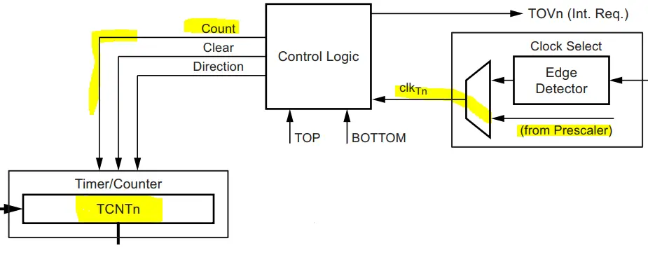
In time mode, the timer module will keep counting (0 to 255 or 65535 depending on resolution). At overflow, a timer overflow interrupt is fired and the timer rolls over back to zero and starts counting again.
Arduino Timer Equations
Timer modules in microcontrollers have a general equation which is as follows:

The desired output time interval (TOUT) is equal to the number of timer ticks multiplied by the single tick time. The timer’s tick time is determined by the input clock frequency and the prescaler ratio that you’ve selected. Therefore, the general timer equation can be expressed like this:

And that’s the equation we’ll be using to design timer-based applications (e.g. time interval delays, periodic tasks execution, and much more). You should note that the maximum TOUT is defined by the prescaler ratio configuration. Changing the prescaler will allow us to raise the maximum allowable TOUT time interval generation with the timer module before it overflows.
For example, Timer1 in Arduino UNO is clocked at 16MHz. With a prescaler of 1:1, the Maximum TOUT can be achieved by setting the TicksCount to its maximum value of 65536. This will give us TOUT(Max) = (1×65536)/16M = 4.1ms.
If you need to generate a larger TOUT time interval with that timer module @ 16MHz clock, you need to choose another option for the prescaler. Let’s say you’d like to generate a 500ms timer interrupt as a time-base for your system. This means the TOUT(MAX) needs to be >500ms.
Therefore, setting the prescaler ratio to 1:256 will be the best option. Because it’ll allow a maximum TOUT(MAX) of = (256×65536)/16M = 1.049s. Which is more than the 500ms requirement so it becomes achievable by selecting this larger prescaler ratio. Let’s now discuss how to use the general timer equation and do the required calculations to be able to configure the timer module properly.
Arduino Timer Calculations
The best way to demonstrate timer module calculations is to consider a practical example use case and walk through the calculation process step by step. And that’s what we’re going to do in this section.
Let’s say you’d like to generate a periodic timer interrupt every 100ms and use it as a time base for your system. We’ll be using the Timer1 module which is clocked at 16MHz (in Arduino UNO boards).
Step 1- Select a suitable prescaler divider. The required TOUT is 100ms. The TOUT(MAX) should be > 100ms. Therefore, selecting a prescaler of 1:64 will be sufficient. Because at 1:64 prescaler, the TOUT(MAX) = (64×65536)/16M = 262ms. Which is definitely above the required 100ms time interval.
Step 2- Using the general timer equation, plug in the (TOUT value, Prescaler divider, and CLK frequency). Then solve the equation for the TicksCount value.

Step 3- TicksCount = 25,000 ticks. And that’s the output of the calculation that we’ll use thereafter to program the timer module to generate the desired 100ms timer interrupt event.
In the next section below, we’ll see how to proceed further after getting the required timer ticks count to program the Arduino timer interrupt to fire every 100ms as desired in this example.
Arduino Timer Interrupt Code
After calculating the required timer TicksCount to achieve the desired TOUT time interval for timer interrupt events, we can go about programming the Arduino timer module in two different ways.
1- Timer Preloading
The first method is to preload the timer register (TCNTx) with a value in such a way it reached overflow (65535) after only TicksCount ticks. For the previous 100ms example, the TicksCount turned out to be 25000 ticks. Therefore, the timer preload value = 65535-25000 = 40535.
By writing 40535 to the TCNTx register, we guarantee that it’s going to tick 25000 ticks to reach the overflow state. In the timer overflow interrupt ISR handler, we’ll also need to preload the TCNTx register with the same value and keep repeating over and over again.
Here is an Arduino code example for Timer Preloading.
|
1 2 3 4 5 6 7 8 9 10 11 12 13 14 15 16 17 18 19 20 21 22 23 24 25 26 |
/* * LAB Name: Arduino Timer Preloading * Author: Khaled Magdy * For More Info Visit: www.DeepBlueMbedded.com */ ISR(TIMER1_OVF_vect) { TCNT1 = 40535; // Timer Preloading // Handle The 100ms Timer Interrupt //... } void setup() { TCCR1A = 0; // Init Timer1 TCCR1B = 0; // Init Timer1 TCCR1B |= B00000011; // Prescalar = 64 TCNT1 = 40535; // Timer Preloading TIMSK1 |= B00000001; // Enable Timer Overflow Interrupt } void loop() { // Do Nothing } |
2- Timer Compare Match Registers
An easier way to achieve the same goal without disrupting the timer’s TCNTx register’s value would be to use the compare match interrupt events. This is probably the best way to implement timer-based interrupt events. Because it gives you two (COMPA and COMPB) registers to generate two independent timer interrupt events using the same timer module.
Considering the previous 100ms time interval interrupt example, we need the timer to tick 25000 ticks to get the 100ms periodic interrupt. So, we’ll use COMPA compare register, enable its interrupt, and set its value to 25000. When a compare match occurs (when TCNT1 = OCR1A), an interrupt is fired. And that’s the 100ms periodic interrupt we want.
To keep it running at the same 100ms rate, we need to update the COMPA value because the timer’s count has now reached 25000. Therefore, we need to add 25000 ticks to the COMPA value. Don’t worry about overflow, at 65535, the register will roll over back to zero exactly like the timer’s TCNTx register does. So it’s going to work flawlessly all the time.
And that’s it! Here is an Arduino code example for Timer Compare Match Interrupt.
|
1 2 3 4 5 6 7 8 9 10 11 12 13 14 15 16 17 18 19 20 21 22 23 24 25 26 |
/* * LAB Name: Arduino Timer Compare Match Interrupt * Author: Khaled Magdy * For More Info Visit: www.DeepBlueMbedded.com */ ISR(TIMER1_COMPA_vect) { OCR1A += 25000; // Advance The COMPA Register // Handle The 100ms Timer Interrupt //... } void setup() { TCCR1A = 0; // Init Timer1 TCCR1B = 0; // Init Timer1 TCCR1B |= B00000011; // Prescalar = 64 OCR1A = 25000; // Timer CompareA Register TIMSK1 |= B00000010; // Enable Timer COMPA Interrupt } void loop() { // Do Nothing } |
Timer Prescaler & TOUT Relationship
The table below summarizes the relationship between the timer prescaler divider ratio and the allowable TOUT time interval minimum & maximum values. The minimum TOUT value is achieved by setting the timer to tick only 1 tick, while maximum TOUT is achieved by letting the timer run from 0 up to overflow (255 or 65535).
This table is assuming you’re using Arduino UNO (Atmega328p) that runs @ 16MHz clock rate. It’ll definitely help you pick the suitable prescaler value for your desired TOUT time interval.
| Timer0 | Timer1 | Timer2 | ||||
| Prescaler | Min TOUT | Max TOUT | Min TOUT | Max TOUT | Min TOUT | Max TOUT |
| 1 | 62.5ns | 16μs | 62.5ns | 4.1ms | 62.5ns | 16μs |
| 8 | 0.5μs | 128μs | 0.5μs | 32.8ms | 0.5μs | 128μs |
| 32 | – | – | – | – | 2μs | 512μs |
| 64 | 4μs | 1.024ms | 4μs | 262ms | 4μs | 1.024ms |
| 128 | – | – | – | – | 8μs | 2.05ms |
| 256 | 16μs | 4.1ms | 16μs | 1.05s | 16μs | 4.1ms |
| 1024 | 64μs | 16.4ms | 64μs | 4.2s | 64μs | 16.4ms |
|
* Min TOUT is when TicksCount = 1 * Max TOUT is when TicksCount = 256 (For Timer0, 2) or 65536 (For Timer1) |
||||||
Arduino Timer Calculator & Code Generator
To make things much easier & quicker for you, here is an Arduino Timer Interrupt Calculator & Code Generator Tool. This tool will take your desired time interval, timer module’s number, and type of interrupt signal you’d like to use. And it’ll give you a complete Arduino startup sketch ready for your project. You can either copy & paste it as is or just get the configurations, timer prescaler, and timer preload value.
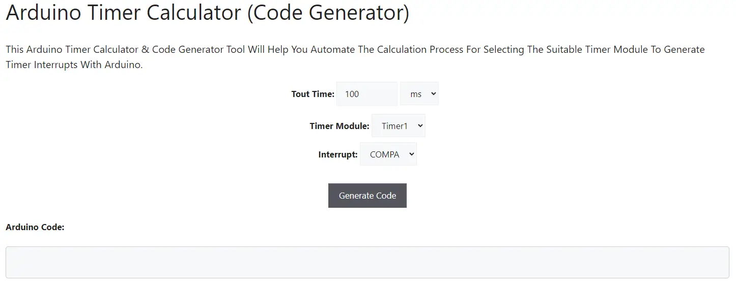
Recall the two timer interrupt implementation techniques from the previous section because we’ll need that to understand the code output of this code generation tool.
- Timer Preloading (OVF)
- Timer Compare Match Registers (COMPA & COMPB)
1- Timer Preloading (OVF)
If you select interrupt type (OVF) which is timer overflow, the generated code will be an implementation for timer preloading technique that we’ve demonstrated in the previous section.
The only downside of it is that it only generates one interrupt and you can’t “freely” set compare match interrupts beside it without getting disrupted. You technically can use COMPA & COMPB alongside timer OVF interrupt, but make sure that the COMPA/B value is larger than the Timer Preloading value.
If you’d like to achieve 25000 ticks to fire a COMPA interrupt while using timer overflow (OVF) technique which is preloading a value of 20000 into the TCNTx, then you need to set the OCRxA register to 20000+25000 = 45000. Instead of just writing a 25000 straight into the OCRxA register.
So both techniques can be used simultaneously but it needs extra careful implementation.
2- Timer Compare Match Registers
If you select interrupt type (COMPA or COMPB), the generated code will be an implementation for the timer compare match interrupt technique that we’ve discussed in the previous section as well.
The good thing about it is that you can generate two periodic interrupts at two different time intervals using the same hardware timer module using this timer compare match interrupts technique.
3- No Code Generated
If your settings for the desired timer interrupt interval exceeds what can be achieved with the selected timer, no code will be generated. Because the selected hardware timer will overflow. You can change the selected hardware timer and try again.
Timer0, 2 will not generate a time interval larger than 16.4ms. While Timer1 can give you up to 4.19s time interval interrupts.
Let’s say you exclusively want to use Timer2 only and would like to get a periodic interrupt of 100ms. The code generator tool will tell you that its beyond the limits of that timer but you can do a workaround however.
Set the desired time to 10ms (which is feasible) and generate the code. In the generated code ISR handler, create a counter and count 10 consecutive interrupts then execute your desired functionality with 100ms periodicity. It’s as simple as this!
Arduino Timer Interrupt Example
In this example project, we’ll test Arduino Timer interrupts. We’ll use the timer overflow interrupt (OVF) and timer preloading technique. The code is generated with this tool and modified for our test project requirements.
We’ll generate a 100ms periodic Timer1 interrupt, in the ISR function we’ll toggle an output LED to check the timing of the event.
Arduino Timer Interrupt Example (OVF) Code
Here is the full code listing for this Arduino Timer Interrupt Example.
|
1 2 3 4 5 6 7 8 9 10 11 12 13 14 15 16 17 18 19 20 21 22 23 24 25 26 27 |
/* * LAB Name: Arduino Timer Overflow Interrupt * Author: Khaled Magdy * For More Info Visit: www.DeepBlueMbedded.com */ ISR(TIMER1_OVF_vect) { TCNT1 = 40535; // Timer Preloading // Handle The Timer Overflow Interrupt digitalWrite(LED_BUILTIN, !digitalRead(LED_BUILTIN)); } void setup() { TCCR1A = 0; // Init Timer1A TCCR1B = 0; // Init Timer1B TCCR1B |= B00000011; // Prescaler = 64 TCNT1 = 40535; // Timer Preloading TIMSK1 |= B00000001; // Enable Timer Overflow Interrupt pinMode(LED_BUILTIN, OUTPUT); } void loop() { // Do Nothing } |
Code Explanation
ISR(TIMER1_OVF_vect)
This is the timer overflow interrupt ISR handler function in which we must always do the timer preloading at the beginning of it, then we’re free to handle the timer interrupt event. In this example, we only toggle the built-in LED output pin.
|
1 2 3 4 5 6 |
ISR(TIMER1_OVF_vect) { TCNT1 = 40535; // Timer Preloading // Handle The Timer Overflow Interrupt digitalWrite(LED_BUILTIN, !digitalRead(LED_BUILTIN)); } |
setup()
in the setup() function, we’ll configure & initialize the timer module (this is auto-generated using our online tool). Then, we need to set the LED pin to be an output pin.
|
1 2 3 4 5 6 7 8 9 |
void setup() { TCCR1A = 0; // Init Timer1A TCCR1B = 0; // Init Timer1B TCCR1B |= B00000011; // Prescaler = 64 TCNT1 = 40535; // Timer Preloading TIMSK1 |= B00000001; // Enable Timer Overflow Interrupt pinMode(LED_BUILTIN, OUTPUT); } |
loop()
in the loop() function, nothing needs to be done.
TinkerCAD Simulation
Here is the simulation result for this project on the TinkerCAD simulator. You can run it as is, or make a copy and add your own code and start running the simulation to see how it’s going to behave.
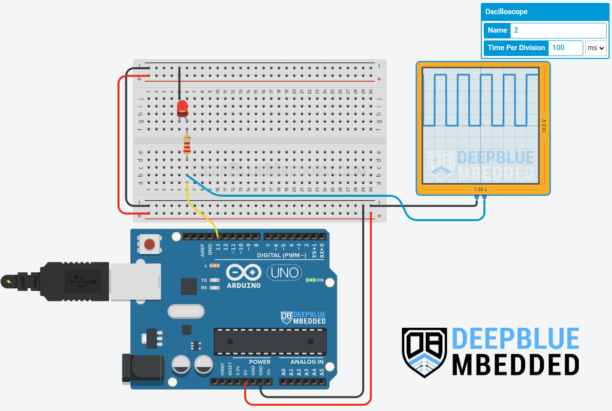
You can check this simulation project on TinkerCAD using this link.
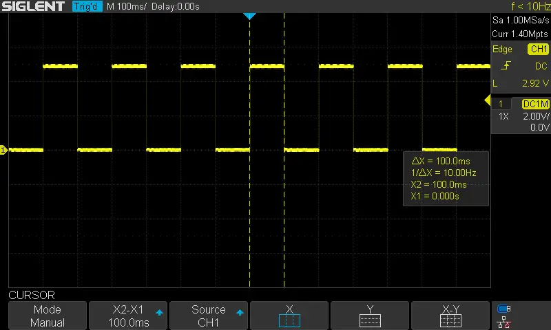
Testing Results
It’s a perfect 100ms pin toggle event exactly as we have expected.
Arduino Timer Interrupt Compare Match Example1
In this example project, we’ll test Arduino Timer interrupts. We’ll use the timer compare match interrupt (COMPA). The code is generated with this tool and modified for our test project requirements.
We’ll generate a 100ms periodic Timer1 interrupt, in the ISR function we’ll toggle an output LED to check the timing of the event.
Arduino Timer Interrupt Example (COMPA) Code
|
1 2 3 4 5 6 7 8 9 10 11 12 13 14 15 16 17 18 19 20 21 22 23 24 25 26 27 |
/* * LAB Name: Arduino Timer Compare Match Interrupt * Author: Khaled Magdy * For More Info Visit: www.DeepBlueMbedded.com */ ISR(TIMER1_COMPA_vect) { OCR1A += 25000; // Advance The COMPA Register // Handle The Timer Interrupt digitalWrite(LED_BUILTIN, !digitalRead(LED_BUILTIN)); } void setup() { TCCR1A = 0; // Init Timer1A TCCR1B = 0; // Init Timer1B TCCR1B |= B00000011; // Prescaler = 64 OCR1A = 25000; // Timer Compare1A Register TIMSK1 |= B00000010; // Enable Timer COMPA Interrupt pinMode(LED_BUILTIN, OUTPUT); } void loop() { // Do Nothing } |
Code Explanation
ISR(TIMER1_COMPA_vect)
This is the timer compare match (A) interrupt ISR handler function in which we must always advance the compare register value with the calculated TicksCount at the beginning of it, then we’re free to handle the timer interrupt event. In this example, we only toggle the built-in LED output pin.
|
1 2 3 4 5 6 |
ISR(TIMER1_COMPA_vect) { OCR1A += 25000; // Advance The COMPA Register // Handle The Timer Interrupt digitalWrite(LED_BUILTIN, !digitalRead(LED_BUILTIN)); } |
setup()
in the setup() function, we’ll configure & initialize the timer module (this is auto-generated using our online tool). Then, we need to set the LED pin to be an output pin.
|
1 2 3 4 5 6 7 8 9 |
void setup() { TCCR1A = 0; // Init Timer1A TCCR1B = 0; // Init Timer1B TCCR1B |= B00000011; // Prescaler = 64 OCR1A = 25000; // Timer Compare1A Register TIMSK1 |= B00000010; // Enable Timer COMPA Interrupt pinMode(LED_BUILTIN, OUTPUT); } |
loop()
in the loop() function, nothing needs to be done.
Proteus Simulation
Here is the simulation result for this project on the Proteus (ISIS) simulator. The TinkerCAD simulation for this example will not produce a reliable behavior maybe due to inaccuracies in the microcontroller model in the simulation environment. The proteus simulation is way more accurate and behaves exactly like the real Arduino UNO board.
Moreover, we’ve got a better and much more powerful set of virtual measurement tools (oscilloscope, function generator, multimeters, etc).
Testing Results
It’s a perfect 100ms pin toggle event exactly as we have expected and seen in simulation.

Check out the tutorial below to help you get started with simulating your Arduino projects in the Proteus simulation environment.
This article will provide you with more in-depth information about using proteus ISIS for Arduino projects simulation.
Arduino Timer Interrupt Compare Match Example2
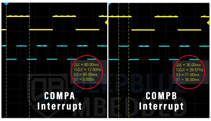
We’ll use only Timer1 for this example project, we’ll set the compare match (A) to fire an interrupt every 80ms. And compare match (B) to fire an interrupt every 35ms. In each ISR, we’ll toggle a different output pin and measure the resulting pin toggle event timing.
Arduino Timer Interrupts Example (COMPA+COMPB)
|
1 2 3 4 5 6 7 8 9 10 11 12 13 14 15 16 17 18 19 20 21 22 23 24 25 26 27 28 29 30 31 32 33 34 35 36 37 38 |
/* * LAB Name: Arduino Timer Compare Match (A+B) Interrupts * Author: Khaled Magdy * For More Info Visit: www.DeepBlueMbedded.com */ #define LED_A_PIN 13 #define LED_B_PIN 8 ISR(TIMER1_COMPA_vect) { OCR1A += 20000; // Advance The COMPA Register // Handle The Timer Interrupt digitalWrite(LED_A_PIN, !digitalRead(LED_A_PIN)); } ISR(TIMER1_COMPB_vect) { OCR1B += 8750; // Advance The COMPB Register // Handle The Timer Interrupt digitalWrite(LED_B_PIN, !digitalRead(LED_B_PIN)); } void setup() { TCCR1A = 0; // Init Timer1A TCCR1B = 0; // Init Timer1B TCCR1B |= B00000011; // Prescaler = 64 OCR1A = 20000; // Timer Compare1A Register OCR1B = 8750; // Timer Compare1B Register TIMSK1 |= B00000110; // Enable Timer COMPA+COMPB Interrupts pinMode(LED_A_PIN, OUTPUT); pinMode(LED_B_PIN, OUTPUT); } void loop() { // Do Nothing } |
Code Explanation
ISR(TIMER1_COMPA_vect)
This is the timer compare match (A) interrupt ISR handler function in which we must always advance the compare register value with the calculated TicksCount at the beginning of it, then we’re free to handle the timer interrupt event. In this example, we only toggle the LED_A output pin.
|
1 2 3 4 5 6 |
ISR(TIMER1_COMPA_vect) { OCR1A += 20000; // Advance The COMPA Register // Handle The Timer Interrupt digitalWrite(LED_A_PIN, !digitalRead(LED_A_PIN)); } |
ISR(TIMER1_COMPB_vect)
This is the timer compare match (B) interrupt ISR handler function in which we must always advance the compare register value with the calculated TicksCount at the beginning of it, then we’re free to handle the timer interrupt event. In this example, we only toggle the LED_B output pin.
|
1 2 3 4 5 6 |
ISR(TIMER1_COMPB_vect) { OCR1B += 8750; // Advance The COMPB Register // Handle The Timer Interrupt digitalWrite(LED_B_PIN, !digitalRead(LED_B_PIN)); } |
setup()
in the setup() function, we’ll configure & initialize the timer module (this is auto-generated using our online tool). Then, we need to set the LED pins’ mode to output.
|
1 2 3 4 5 6 7 8 9 10 11 |
void setup() { TCCR1A = 0; // Init Timer1A TCCR1B = 0; // Init Timer1B TCCR1B |= B00000011; // Prescaler = 64 OCR1A = 20000; // Timer Compare1A Register OCR1B = 8750; // Timer Compare1B Register TIMSK1 |= B00000110; // Enable Timer COMPA+COMPB Interrupts pinMode(LED_A_PIN, OUTPUT); pinMode(LED_B_PIN, OUTPUT); } |
loop()
in the loop() function, nothing needs to be done.
Proteus Simulation
Here is the simulation result for this project on the Proteus (ISIS) simulator.
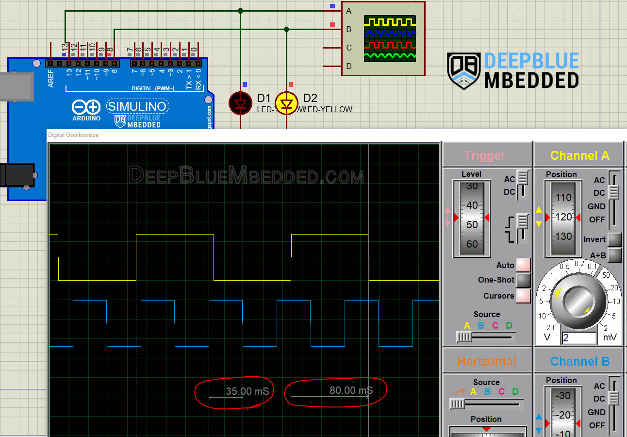
Testing Results
It shows a perfect 80ms pin toggle event & another 35ms pin toggle event, exactly as we have expected and seen in the simulation.
Parts List
Here is the full components list for all parts that you’d need in order to perform the practical LABs mentioned here in this article and for the whole Arduino Programming series of tutorials found here on DeepBlueMbedded. Please, note that those are affiliate links and we’ll receive a small commission on your purchase at no additional cost to you, and it’d definitely support our work.
Download Attachments
You can download all attachment files for this Article/Tutorial (project files, schematics, code, etc..) using the link below. Please consider supporting my work through the various support options listed in the link down below. Every small donation helps to keep this website up and running and ultimately supports our community.
Wrap Up
To conclude this tutorial, we’d like to highlight the fact that the Arduino Timer interrupts are very useful in so many applications in which you need your Arduino to periodically handle various events or to add time delays without blocking the CPU with generic delay() function calls.
It needs careful implementation for the ISR handler functions to keep it as efficient as possible. And using this Arduino Timer Calculator & Code Generator Tool will make things easier and quicker for you.
This tutorial is a fundamental part of our Arduino Series of Tutorials because we’ll build on top of it to interface various sensors and modules with Arduino in other tutorials & projects. So make sure you get the hang of it and try all provided code examples & simulations (if you don’t have your Arduino Kit already).
If you’re just getting started with Arduino, you need to check out the Arduino Getting Started [Ultimate Guide] here.
This is the ultimate guide for getting started with Arduino for beginners. It’ll help you learn the Arduino fundamentals for Hardware & Software and understand the basics required to accelerate your learning journey with Arduino Programming.
![Arduino Timers Tutorial [Ultimate Guide] Arduino Timers Tutorial [Ultimate Guide]](https://deepbluembedded.com/wp-content/uploads/2023/05/Arduino-Timers-Tutorial-Ultimate-Guide-300x169.jpg)
