In this tutorial, we’ll discuss Arduino Input Capture Unit from the fundamental concepts all the way to implementing Arduino Input Capture applications. We’ll start off by discussing what is a timer, how it works, and the working principles of Arduino timers in input capture mode.
We’ll create a couple of Arduino Input Capture Example Code Projects in this tutorial to practice what we’ll learn all the way through. And finally, we’ll draw some conclusions and discuss some applications & use cases for Arduino Timer (Input Capture Mode) that will definitely help you take some guided design decisions in your next projects. Without further ado, let’s get right into it!
Table of Contents
- Arduino Timers
- Arduino Input Capture Unit (Mode)
- Arduino Input Capture Code
- Arduino Input Capture Example
- Arduino Input Capture Unit Applications
- Arduino Input Capture Wrap Up
Arduino Timers
Timer modules in Arduino provide precise timing functionality. They allow us to perform various tasks, such as generating accurate delays, creating periodic events, measuring time intervals, and meeting the time requirements of the target application.
Each Arduino board has its target microcontroller that has its own set of hardware timers. Therefore, we always need to refer to the respective datasheet of the target microcontroller to know more about its hardware capabilities and how to make the best use of it.
1. Arduino Hardware Timers
Arduino UNO (Atemga328p) has 3 hardware timers which are:
- Timer0: 8-Bit timer
- Timer1: 16-Bit timer
- Timer2: 8-Bit timer
Those timer modules are used to generate PWM output signals and provide timing & delay functionalities to the Arduino core, and we can also use them to run in any mode to achieve the desired functionality as we’ll see later on in this tutorial.
Each hardware timer has a digital counter register at its core that counts up based on an input clock signal. If the clock signal is coming from a fixed-frequency internal source, then it’s said to be working in timer mode. But if the clock input is externally fed from an IO or any async source, it’s said to be working as a counter that counts incoming pulses.
2. Arduino Timer Prescaler
A prescaler in a hardware timer module is a digital circuit that is used to divide the clock signal’s frequency by a configurable number to bring down the timer clock rate so it takes longer to reach the overflow (maximum count number).
This is really useful to control the maximum time interval that can be generated using the timer module, the PWM output frequency, or the range of time that can be measured using the timer module.
Running the timer module at the system frequency is good for resolution but will generate so many timer overflow interrupts that needs extra care in your code. Hence, using a prescaler can be useful to avoid this situation in the first place if needed.
In timer mode, the timer module will have the internal clock of the system as a clock source and it passes through the prescaler as shown below. You can programmatically control the division ratio of the prescaler to control the timer input clock frequency as you need.

The timer prescaler divider values differ from one timer module to another and it’s clearly stated in the datasheet for each timer module (Timer0, 1, and 2).
3. Arduino Timers Comparison
This is a summarized table for Arduino UNO (Atmega328p) timers, differences between them, capabilities, operating modes, interrupts, and use cases.
| Timer0 | Timer1 | Timer2 | |
| Resolution | 8 Bits | 16 Bits | 8 Bits |
| Used For PWM Output Pins# | 5, 6 | 9, 10 | 11, 3 |
| Used For Arduino Functions |
delay() millis() micros() | Servo Functions | tone() |
| Timer Mode | ✓ | ✓ | ✓ |
| Counter Mode | ✓ | ✓ | ✓ |
| Output Compare (PWM) Mode | ✓ | ✓ | ✓ |
| Input Capture Unit Mode | – | ✓ | – |
| Interrupts Vectors |
TIMER0_OVF_vect TIMER0_COMPA_vect TIMER0_COMPB_vect |
TIMER1_OVF_vect TIMER2_COMPA_vect TIMER1_COMPB_vect TIMER1_CAPT_vect |
TIMER2_OVF_vect TIMER2_COMPA_vect TIMER2_COMPB_vect |
| Prescaler Options | 1:1, 1:8, 1:64, 1:256, 1:1024 | 1:1, 1:8, 1:64, 1:256, 1:1024 | 1:1, 1:8, 1:32, 1:64, 1:128, 1:256, 1:1024 |
Playing with any timer configurations can and will disrupt the PWM output channels associated with that module. Moreover, changing the configurations of timer0 will disrupt the Arduino’s built-in timing functions ( delay, millis, and micros). So keep this in mind to make better design decisions in case you’ll be using a hardware timer module for your project. Timer1 can be the best candidate so to speak.
4. Arduino Timers Control Registers
We can initialize, configure, and control Arduino Timers & Timer Interrupts using the associated registers as stated in the datasheet. The Timer-associated registers are as follows:
- TCCRxA: Timer/Counter Control Register A.
- TCCRxB: Timer/Counter Control Register B.
- TCNTx: Timer/Counter Registers.
- OCRxA: Output Compare A Register.
- OCRxB: Output Compare B Register.
- ICRx: Input Capture Register.
- TMISKx: Timer Interrupts Mask Register, enable/disable timer interrupts.
- TIFRx: Timer interrupts Flag Bits Register, read/clear timer interrupt flag bits.
Where x can be 0, 1, or 2 for timers (Timer0, Timer1, and Timer2) respectively. More details on the functionality that each bit controls and what are its different options can be found in the datasheet of the microcontroller.
For more information about Arduino Timers, fundamental concepts, different timer operating modes, and code examples, it’s highly recommended to check out the tutorial linked below. It’s the ultimate guide for Arduino Timers.
This article will give more in-depth information about Arduino Timers, how timers work, different timer operating modes, practical use cases and code examples, and everything you’d ever need to know about Arduino Timers.
Arduino Input Capture Unit (Mode)
The timer module in input capture mode is configured to have an internal clock source with multiple prescaler options. It’s generally used to capture the timer counter value at certain events on the input capture pin (RISING or FALLING edges). The (Input Capture Unit) is also referred to as ICU for short.
The timer module will be free running all the time, and its value (TCNTx) is captured and saved into the input capture register (ICRx) immediately when the input capture pin state has changed. This is like taking a time stamp from the running timer at certain pin state change events (on the ICPn pin).
Input Capture Unit (ICU) Hardware
There are so many applications and use cases for timer modules in input capture mode as we’ll see later on. Here is the block diagram for the hardware timer input capture unit.
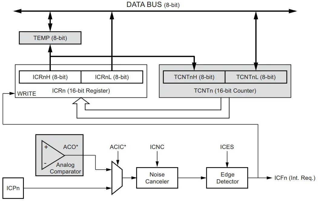
As you can see in the ICU hardware diagram, the timer counter register (TCNTx) is copied to the input capture register (ICRx) when an input capture edge is detected. It can either be coming from the ICPx external pin or from the internal analog comparator output (ACO).
The ICPx pin can trigger an input capture event on RISING or FALLING edges. When an input capture event is triggered, the current timer/counter register (TCNTx) value is copied to the input capture register (ICRx), and an interrupt is fired, if enabled. The Arduino input capture interrupt vector is TIMER1_CAPT_vect.
The main challenge when using the input capture unit is to assign enough processor capacity for handling the incoming events. The time between two events is critical. If the processor has not read the captured value in the ICRx register before the next event occurs, the ICRx will be overwritten with a new value. In this case, the result of the capture will be incorrect.
When using the input capture interrupt, the ICRx register should be read as early in the interrupt handler routine as possible. Even though the input capture interrupt has relatively high priority, the maximum interrupt response time is dependent on the maximum number of clock cycles it takes to handle any of the other interrupt requests
Input Capture Unit Trigger Sources
The main trigger source for the input capture unit is the input capture pin (ICPx). The ICU can alternatively use the analog comparator output as a trigger source for the input capture unit. The analog comparator is selected as a trigger source by setting the analog comparator input capture (ACIC) bit in the analog comparator control and status register (ACSR).
Be aware that changing the trigger source can trigger a capture. The input capture flag must therefore be cleared after the change. An input capture can also be triggered by software by controlling the port of the ICPx pin. This is one additional way of generating Arduino Software Interrupts.
Input Capture Noise Cancellation
There is also a noise cancellation circuit that can be enabled or disabled that filters out any glitches in the ICPx input pin signal or the analog comparator’s output. It does this by taking 4 consecutive samples of the input signal, if it’s been the same for the 4 samples, it’ll change the output that triggers the edge detector consequently.
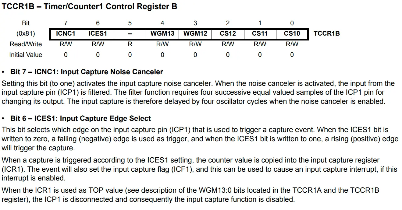
The noise canceler is enabled by setting the input capture noise canceler (ICNC1) bit in the (TCCR1B) register. When enabled the noise canceler introduces additional four system clock cycles of delay from a change applied to the input, to the update of the ICR1 register. The noise canceler uses the system clock and is therefore not affected by the prescaler.
Input Capture Unit Frequency Measurement
As stated earlier, the ICU mode is typically used to get time stamps of a free running timer module at certain events on an external pin (ICPx). Which can be very useful for applications like frequency measurement. We can set up the ICU to trigger a capture event on every RISING edge on the ICPx pin to measure an external signal’s frequency.
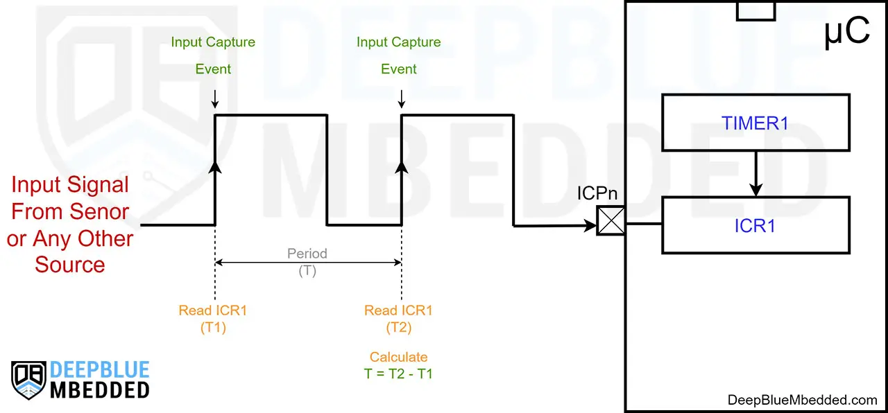
At the first edge, we’ll save the ICRx register reading into a variable (T1). At the second edge, we’ll save ICRx into (T2). And to get the signal’s period, we just subtract the time stamps as follows: ( T = T2 - T1). Just pay attention to timer overflow events because if T2 is smaller than T1, the resulting period (T) will be negative which is not correct. We need to add ( Number of TimerOVF * 65536) to T2 to get the correct absolute timestamp difference.
Here is an interactive simulator tool that will help you understand how the input capture unit works. It captures the timer value on the RISING edge of the button below, try it yourself and see how things & calculations work out on the right side.
Input Capture Unit Interactive Simulation
Duty Cycle (Pulse Width) Measurement With ICU
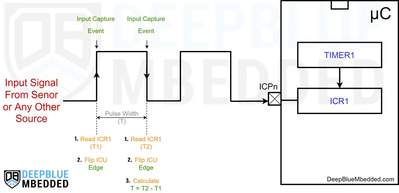
Measurement of an external signal’s duty cycle (pulse width) requires that the trigger edge is changed after each capture event. Changing the edge sensing must be done as early as possible after the ICRx register has been read. After a change of the edge, the input capture flag (ICFx) must be cleared by software (writing a logical one to the bit location).
You can refer to the Arduin UNO Pinout Guide to identify all timer input capture pins (ICPn).
In Arduino UNO (Atmega328p) microcontroller, Only Timer1 has an input capture unit (timer mode). Which has an input capture pin (ICP1) that corresponds to Arduino UNO IO pin8.
Arduino Input Capture Code
To set an Arduino Timer module to operate in input capture mode, we'll use the clock selection bits in the TCCRxB register. Here are the clock options for the least significant 3 bits in the TCCRxB register (as stated in the datasheet).

We need also to configure the input capture pin edge detection mode (RISING or FALLING) using the ICES bit in the TCCRxB register. And it's up to you to enable or disable the ICU input filter (noise cancellation) using the ICNC bit in the same register. Which is recommended to be enabled in my opinion.
The ICES and ICNC bits are the bits 6 and 7 respectively in the TCCRxB register.
You always need to enable the input capture unit (ICU) interrupt to be able to read the captured timer value as soon as it's captured. Any delay in reading the last captured timer value from the ICRx (input capture register) raises the risk of it being overwritten by the next capture event. Therefore, you always need to enable the ICU interrupt & read the ICRx register as soon as possible in the ISR handler function.
Here is an example of an Arduino Input Capture Code that sets Timer1 to operate in Input Capture Mode (it's free running & input capture event is triggered on RISING edges of the ICP1 pin).
I've also enabled the timer overflow (OVF) interrupt to keep track of how many overflow events have occurred. The goal of this code example is to measure the frequency of an input signal using the input capture unit. We read T1, T2, and calculate the absolute time difference (T = T2-T1). Then, the frequency is simply (1/T).
|
1 2 3 4 5 6 7 8 9 10 11 12 13 14 15 16 17 18 19 20 21 22 23 24 25 26 27 28 29 30 31 32 33 34 35 36 37 38 39 40 41 42 43 |
bool MeasEnd = 0; uint16_t T1, T2, T1OVF_Counter = 0; unsigned long T, Freq = 0; ISR(TIMER1_OVF_vect) { T1OVF_Counter++; } ISR(TIMER1_CAPT_vect) { if(!MeasEnd) { T1 = ICR1; MeasEnd = 1; } else { T2 = ICR1; T = T2 + (65536 * T1OVF_Counter) - T1; if(T == 0) { Freq = 0; } else { Freq = (unsigned long)(16000000/T); } T1OVF_Counter = 0; MeasEnd = 0; } } void setup() { TCCR1A = 0; // Init Timer1A TCCR1B = 0; // Init Timer1B TCCR1B |= B11000001; // Internal Clock, Prescaler = 1, ICU Filter EN, ICU Pin RISING TIMSK1 |= B00100001; // Enable Timer OVF & CAPT Interrupts } void loop() {} |
Arduino Input Capture Example
In this example project, we'll test the Arduino input capture unit. We'll create a simple frequency counter project that measures an input signal's frequency and display it on an LCD screen.
Wiring
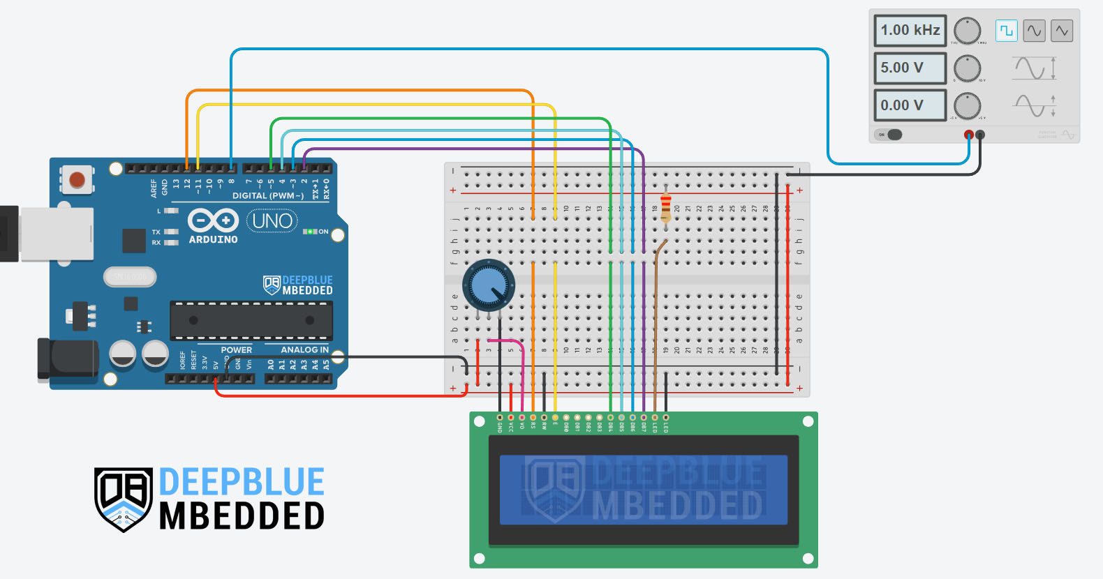
Here is how to hook up the LCD 16x2 with Arduino and the function generator signal to the ICP1 (pin8).
Arduino Input Capture Frequency Counter Example Code
Here is the full code listing for this Arduino Frequency Counter Based on the input capture unit for time measurement.
|
1 2 3 4 5 6 7 8 9 10 11 12 13 14 15 16 17 18 19 20 21 22 23 24 25 26 27 28 29 30 31 32 33 34 35 36 37 38 39 40 41 42 43 44 45 46 47 48 49 50 51 52 53 54 55 56 57 58 59 60 61 62 63 64 65 66 |
/* * LAB Name: Arduino Input Capture (Frequency Measurement) * Author: Khaled Magdy * For More Info Visit: www.DeepBlueMbedded.com */ #include <LiquidCrystal.h> bool MeasEnd = 0; uint16_t T1OVF_Counter = 0; unsigned long T1 = 0, T2 = 0, T = 0, Freq = 0; LiquidCrystal MyLCD(12, 11, 5, 4, 3, 2); // Creates an LCD object, Parameters: (RS, EN, D4, D5, D6, D7) ISR(TIMER1_OVF_vect) { T1OVF_Counter++; } ISR(TIMER1_CAPT_vect) { if(!MeasEnd) { T1 = ICR1; MeasEnd = 1; } else { T2 = ICR1; if(T1OVF_Counter) { T = T2 + (65536 * T1OVF_Counter) - T1; } else { T = T2 - T1; } if(T == 0) { Freq = 0; } else { Freq = (2000000/T); } T1OVF_Counter = 0; MeasEnd = 0; } } void setup() { TCCR1A = 0; // Init Timer1A TCCR1B = 0; // Init Timer1B TCCR1B |= B11000010; // Internal Clock, Prescaler = 8, ICU Filter EN, ICU Pin RISING TIMSK1 |= B00100001; // Enable Timer OVF & CAPT Interrupts MyLCD.begin(16, 2); // Set up the number of columns and rows on the LCD. } void loop() { MyLCD.clear(); MyLCD.setCursor(0, 0); MyLCD.print("Frequency:"); MyLCD.setCursor(0, 1); MyLCD.print(Freq); delay(50); } |
Code Explanation
ISR(TIMER1_OVF_vect)
This is the ISR interrupt handler for Timer1 overflow events. In which, we should increment the overflow counter variable to keep track of how many overflow events have fired during the measurement cycle. We need to take that into account while calculating the input signal's period (T = T2 - T1).
|
1 2 3 4 |
ISR(TIMER1_OVF_vect) { T1OVF_Counter++; } |
ISR(TIMER1_CAPT_vect)
This is the input capture interrupt ISR handler function. It uses the variable MeasEnd to identify the first edge input capture event from the second rising edge. The measurement cycle starts with capturing the first edge time stamp (T1) and ends with the second edge interrupt at which we capture (T2) and calculate the period (T = T2 - T1).
We also check if T1OVF_Counter is a non-zero value, we'll take that into account by adding (65536 * T1OVF_Counter) to T2 before subtracting T1 to get the period (T). Else, we'll just subtract T1 from T2 and we're good to go.
Frequency is finally calculated and updated by taking the clock frequency after the prescaler divider (8) which becomes 2MHz and dividing that by the total number of timer ticks (the absolute difference between time stamp T1 and time stamp T2).
setup()
in the setup() function, we'll configure & initialize the Timer1 module to operate in input capture Mode, enable the ICU & OVF interrupts, and ICU RISING edge events. And we'll also initialize the LCD display.
|
1 2 3 4 5 |
TCCR1A = 0; // Init Timer1A TCCR1B = 0; // Init Timer1B TCCR1B |= B11000010; // Internal Clock, Prescaler = 8, ICU Filter EN, ICU Pin RISING TIMSK1 |= B00100001; // Enable Timer OVF & CAPT Interrupts MyLCD.begin(16, 2); // Set up the number of columns and rows on the LCD. |
loop()
in the loop() function, we just need to update the LCD display message to show the most recent value for the frequency measurement.
|
1 2 3 4 5 6 |
MyLCD.clear(); MyLCD.setCursor(0, 0); MyLCD.print("Frequency:"); MyLCD.setCursor(0, 1); MyLCD.print(Freq); delay(50); |
Proteus Simulation
Here is the simulation result for this project on the Proteus (ISIS) simulator. The TinkerCAD simulation for this example will not produce a reliable behavior maybe due to inaccuracies in the microcontroller model in the simulation environment. The proteus simulation is way more accurate and behaves exactly like the real Arduino UNO board.
Moreover, we've got a better and much more powerful set of virtual measurement tools (oscilloscope, function generator, multimeters, virtual serial terminal, etc).
Check out the tutorial below to help you get started with simulating your Arduino projects in the Proteus simulation environment.
This article will provide you with more in-depth information about using proteus ISIS for Arduino projects simulation.
Testing Results
Arduino Input Capture Unit Applications
There are so many applications and use cases for timer modules in input capture mode. In this section, we'll discuss some of the most common input capture unit applications that you need to know to make the best use of it if you need it in your next project.
1. Pulse Width (Duty Cycle) Measurement
You can use the Timer in input capture mode to measure the pulse width (duty cycle) of an input signal. By taking a time stamp at the first edge, then flip the ICU triggering edge. On the next edge, an input capture event will also trigger and we'll have two time stamps at the RISING & FALLING edges of the input signal.
By subtracting the time stamps, we can easily find out the input signal's duty cycle (pulse width).
2. Frequency Measurement
By taking two time stamps of the free-running timer at the same edge of the input signal, we can easily identify the input signal's period and then find out the frequency.
This is a very common application for timer modules in input capture mode that's used in devices like (tachometers or motor RPM speed measurement). We can also build a frequency counter project based on Arduino's input counter mode like the one we did in the example project here in this tutorial.
3. Sensors Interfacing
We can interface so many sensors with Arduino using the input capture unit to measure output pulses. Things like ultrasonic sensor HC-SR04, optical encoders, zero-crossing detection for AC signals, and much more.
4. Software Interrupt
This is quite an uncommon application for input capture units but it can be used to generate software-triggered interrupts, if not natively supported by the microcontroller's CPU instruction set. To learn more About Arduino Software Interrupts, you can check out the tutorial below for more in-depth information about this topic.
This article will give more in-depth information about Arduino Software Interrupts, how to generate software interrupts in Arduino, and will also provide an example code for Arduino software interrupts generation.
5. Extra External Interrupt Pin
One obscure application for timer modules in input mode is to use the timer input capture pin (ICPn) as an additional external interrupt pin with a dedicated interrupt vector. You can consider it exactly like (INT0 & INT1) pins.
If you're desperate for one more dedicated interrupt pin like (INTx) not (PCINT), then a timer module in input capture mode can be an exotic solution for such a situation. You can use the ICP1 pin as a dedicated interrupt pin with a dedicated interrupt vector TIMER1_CAPT_vect, and that's it!
Parts List
Here is the full components list for all parts that you'd need in order to perform the practical LABs mentioned here in this article and for the whole Arduino Programming series of tutorials found here on DeepBlueMbedded. Please, note that those are affiliate links and we'll receive a small commission on your purchase at no additional cost to you, and it'd definitely support our work.
Download Attachments
You can download all attachment files for this Article/Tutorial (project files, schematics, code, etc..) using the link below. Please consider supporting my work through the various support options listed in the link down below. Every small donation helps to keep this website up and running and ultimately supports our community.
Arduino Input Capture Wrap Up
To conclude this tutorial, we'd like to highlight the fact that the Arduino Timers in Input Capture Mode are very useful in so many applications as we've discussed earlier. You can easily set up an Arduino timer to operate in Input capture mode and measure input signals' width or frequency using the ICPn pin.
This tutorial is a fundamental part of our Arduino Series of Tutorials because we’ll build on top of it to interface various sensors and modules with Arduino in other tutorials & projects. So make sure you get the hang of it and try all provided code examples & simulations (if you don't have your Arduino Kit already).
If you're just getting started with Arduino, you need to check out the Arduino Getting Started [Ultimate Guide] here.
This is the ultimate guide for getting started with Arduino for beginners. It’ll help you learn the Arduino fundamentals for Hardware & Software and understand the basics required to accelerate your learning journey with Arduino Programming.
![Arduino Timers Tutorial [Ultimate Guide] Arduino Timers Tutorial [Ultimate Guide]](https://deepbluembedded.com/wp-content/uploads/2023/05/Arduino-Timers-Tutorial-Ultimate-Guide-300x169.jpg)
