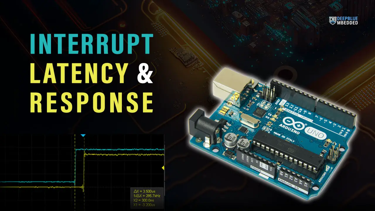
In this tutorial, we’ll discuss Interrupt Latency & Response Time (Interrupt Speed) in Arduino what it means, how you can measure it on your own, and what it does affect in your project. We’ll create a test setup and code example to run the measurement process and discuss the results to draw some conclusions.
Without further ado, let’s get right into it!
Table of Contents
- Interrupt Latency
- Interrupt Response Time
- CPU Context Saving & Switching
- Causes of Interrupt Latency
- Interrupt Latency Measurement 1 – Arduino Example
- Interrupt Latency Measurement 2 – Arduino Example
- Wrap Up
Interrupt Latency
Interrupt Latency is defined to be the time between the actual interrupt request (IRQ) signal and the CPU starting to execute the first instruction of the (ISR) interrupt handler function. And it’s usually expressed in CPU clock cycles or time (in μs or ns).
Each CPU has its own interrupt latency which is dictated by the way it handles interrupt signals and some other hardware implementation variations. So it’s considered to be one of the key characteristics of each CPU that we can assess or measure to know exactly how long it actually is for a given CPU.
In this tutorial, we’ll discuss the reasons behind interrupt latency and a couple of techniques with code examples to measure the interrupt latency in Arduino (Atmega328p) microcontroller.
Interrupt Response Time
Interrupt Response Time is the time between the actual interrupt request (IRQ) signal and the CPU starting to execute the first instruction of the (ISR) interrupt handler function. Which is exactly the same definition for interrupt latency.
There are so many debates online about this and we, me and my work colleagues, did also debate this subject a lot. And the conclusion is: those terms can be used interchangeably to point to the time between a hardware IRQ firing event & start of ISR. If someone wants to point to anything else, this needs to be explicitly stated and avoid using any term of those two. Just to eliminate any misconception or misunderstanding.
CPU Context Saving & Switching
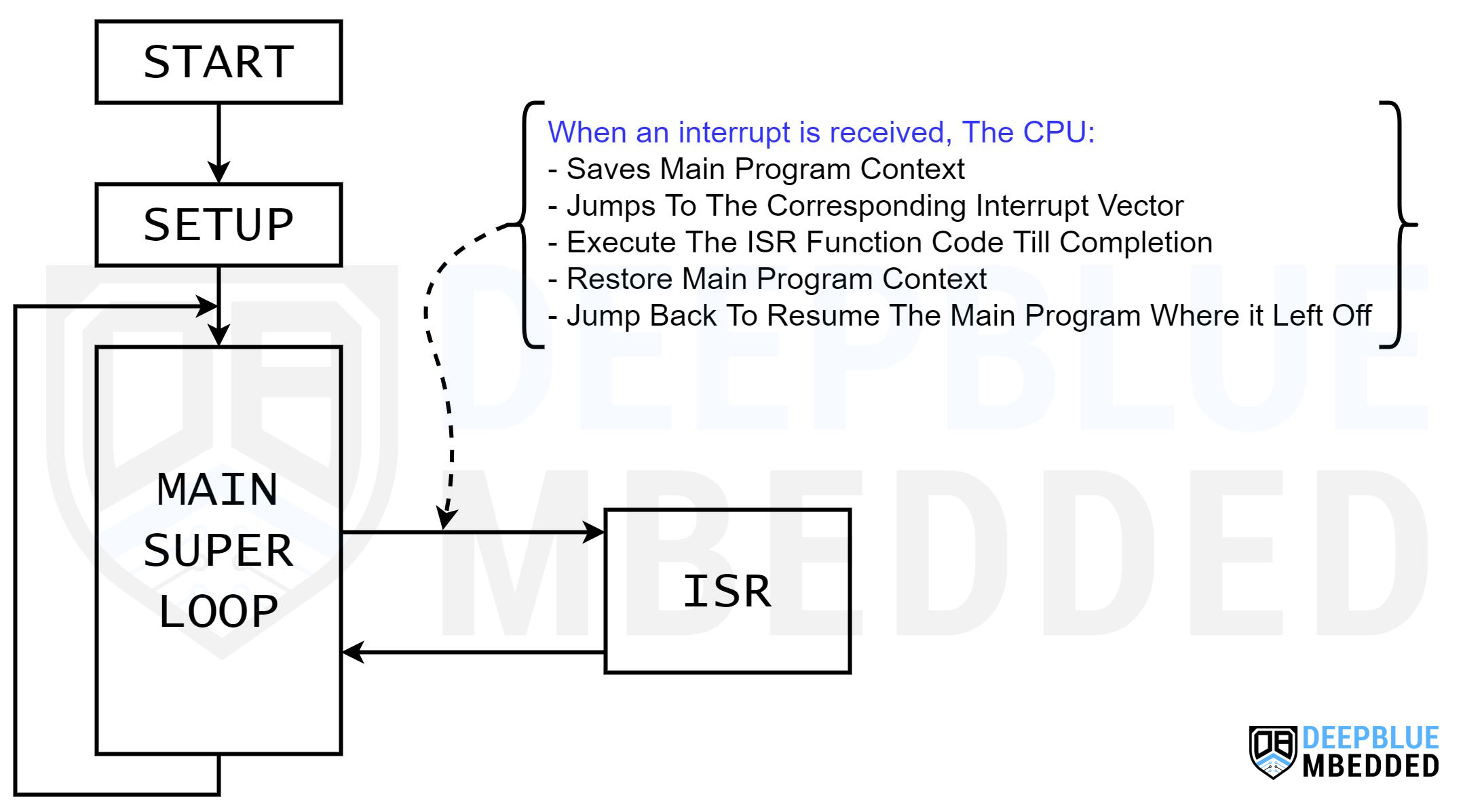
Context Saving & Switching is a process that the CPU needs to do just to smoothly switch between main program execution and ISR handlers. It needs to save the current CPU registers, program counter address, and shadow registers. This is the only way the CPU can know where it left off before jumping to the interrupt vector to execute the ISR function located there.
After finishing the execution of the ISR handler function, the CPU needs to remember where it left off the main program to continue from that point. Therefore, context restoration is needed. So it pops up all saved addresses and registers (context) and jumps back to where it left off the main program.
Context saving and switching take time for the CPU to do and we, roughly, call it interrupt latency. And it happens every time an interrupt signal is received, so if your system is set up in such a way that the CPU receives thousands of interrupts per second, you definitely need to assess the effect of interrupt latency & its contribution to the whole CPU load measurement.
We can’t just simply assume that interrupt latency is only due to the time wasted in CPU context saving and switching. It is however one reason behind interrupt latency but there are still some other contributors to it as we’ll see in the next section hereafter.
Causes of Interrupt Latency
There are so many factors that affect the interrupt latency of a CPU as seen by each ISR handler. The most important causes for interrupt latency are listed below:
- Completion of Current Instruction: In most processor architectures, the processor typically finishes executing the current instruction, even if it takes multiple cycles, before handling the interrupt.
- ISR Selection: Some processor architectures require additional software statements to correctly select the appropriate ISR for the triggered interrupt.
- Context Saving & Switching: To preserve the system’s state upon returning from the Interrupt Service Routine (ISR), the processor saves important core registers, such as the program counter, flag registers, and linker register, onto the stack.
- Fetching & Decoding ISR Instructions: There is a time overhead involved in fetching and decoding the instructions of the ISR, which may impact the overall execution time.
- Memory Speed: Memory systems, like flash memory where the code is stored, often have slower clock frequencies compared to the CPU. This difference in clock speeds can introduce wait states during the ISR execution.
- Higher-Priority Interrupts Nesting: At any point, the to-be-executed interrupt ISR can be interrupted by another higher-priority interrupt, including before the first instruction of the ISR is executed. Which adds to the overall interrupt latency.
- Interrupt Request Sync: The interrupt request signal must be synchronized with the CPU clock timing. This synchronization process may require several cycles for the interrupt signal source to trigger the actual interrupt request.
- External Interrupts Sync: When the interrupt request signal originates from outside the processor device (external interrupts), it must first be synchronized with the bus or peripheral clock before being processed by the CPU.
Each interrupt handler (ISR) has a different interrupt latency value due to its priority or address in the interrupt vector table or even a random event like the in-progress execution of another ISR. Therefore, the interrupt latency measurement is better to be an average value that you take with a grain of salt at the end. Because interrupt latency seen by one ISR is not globally the same across all other ISRs but it’ll be close enough.
Interrupt Latency Measurement 1 – Arduino Example
In this example, we’ll measure the interrupt latency using a GPIO pin and direct register access to accelerate the GPIO pin control. We’ll connect an external push button to an interrupt pin (INT0 = pin2). And in the INT0_ISR function, we’ll drive an IO pin HIGH. The time between the button input pin rising edge and the output pin going HIGH is a measure for the interrupt latency seen by the INT0_ISR function.
We’ll use an oscilloscope to do this manual measurement.
Example Code
Here is the full code listing for the Arduino interrupt latency measurement 1.
|
1 2 3 4 5 6 7 8 9 10 11 12 13 14 15 16 17 18 19 20 21 22 23 24 25 26 27 28 29 30 |
/* * LAB Name: Arduino Interrupt Latency (Speed) Measurement * Author: Khaled Magdy * For More Info Visit: www.DeepBlueMbedded.com */ // ---[ Arduino Pin Manipulation Macros ]--- #define SET_PIN_MODE_OUTPUT(port, pin) DDR ## port |= (1 << pin) #define SET_PIN_HIGH(port, pin) (PORT ## port |= (1 << pin)) #define SET_PIN_LOW(port, pin) ((PORT ## port) &= ~(1 << (pin))) #define INT0_PIN 2 void INT0_ISR(void) { SET_PIN_HIGH(B, 0); delay(1); } void setup() { SET_PIN_MODE_OUTPUT(B, 0); // Set Pin8 (PB0) As Output pinMode(INT0_PIN, INPUT); attachInterrupt(digitalPinToInterrupt(INT0_PIN), INT0_ISR, RISING); } void loop() { SET_PIN_LOW(B, 0); delay(10); } |
Code Explanation
INT0_ISR()
This is the ISR handler function that we’ll use to measure the interrupt latency. At the first instruction of the ISR, we’ll drive the test pin (pin8 or PB0) to HIGH. Then we add a small delay to be able to capture the signal more easily on the oscilloscope before it’s driven LOW in the main loop() afterward.
|
1 2 3 4 5 |
void INT0_ISR(void) { SET_PIN_HIGH(B, 0); delay(1); } |
setup()
in the setup() function, we just need to initialize the IO pins to be used as input & output, then enable interrupt pin2 (INT0) to be triggered at the RISING edge.
|
1 2 3 |
SET_PIN_MODE_OUTPUT(B, 0); // Set Pin8 (PB0) As Output pinMode(INT0_PIN, INPUT); attachInterrupt(digitalPinToInterrupt(INT0_PIN), INT0_ISR, RISING); |
loop()
in the loop() function, we always set the test pin to LOW which is the default (IDLE) state for it.
|
1 2 |
SET_PIN_LOW(B, 0); delay(10); |
Note that in this example, I’m using direct port manipulation for ultra-fast pin access to eliminate the effect of the digitalWrite() function’s execution time on the measurement I’m performing. To learn more about this topic, and you should, it’s highly recommended to check out the tutorial below.
This article will give more in-depth information about Arduino direct port manipulation and register access to control IO pin extremely faster than the default digitalRead & digitalWrite functions.
Proteus (ISIS) Simulation
Another extremely powerful simulation environment for Arduino is the Proteus (ISIS) with Arduino add-on library. It can definitely run our test projects for this tutorial. But you won’t feel its power until you need some virtual test equipment like an oscilloscope, function generator, power supply, and advanced SPICE simulation for auxiliary electronic circuitry that you may build around an Arduino microcontroller.
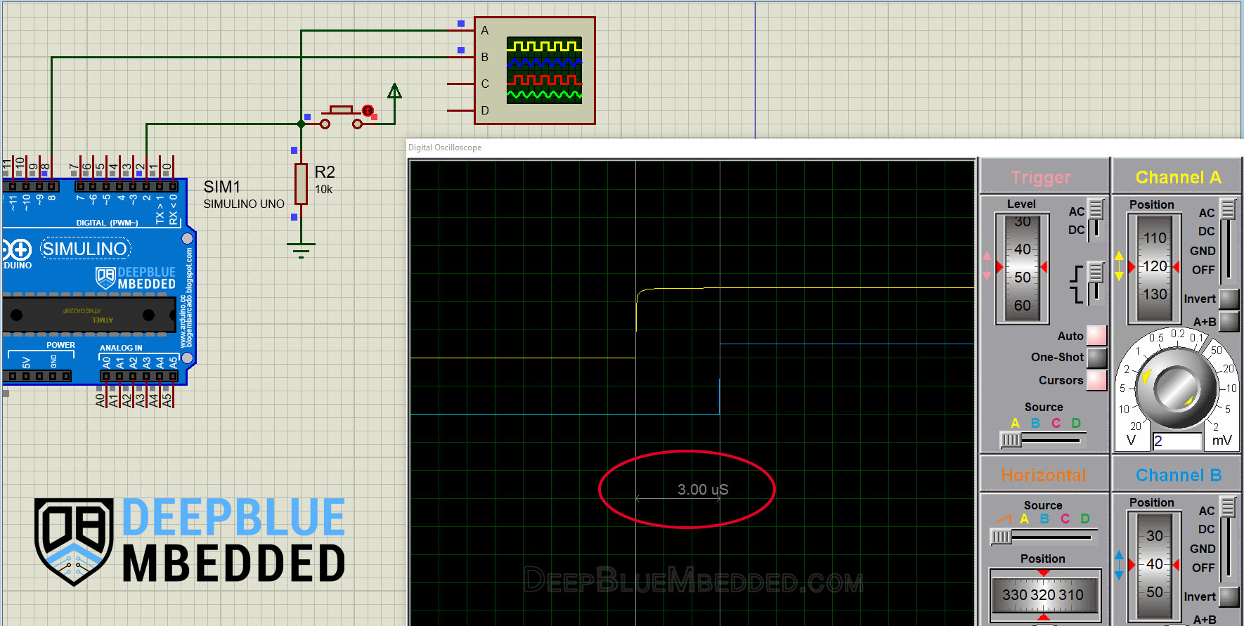
Here is the Arduino project simulation result from the Proteus environment.
Testing Results
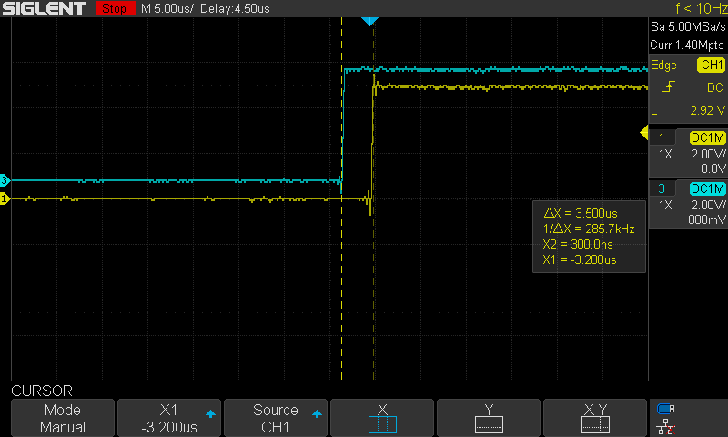
Simulation results are amazingly so close to the real measurement on a real Arduino board with a real oscilloscope. You definitely need to check out the tutorial below to help you get started with simulating your Arduino projects in the Proteus simulation environment.
This article will provide you with more in-depth information about using proteus ISIS for Arduino projects simulation.
Interrupt Latency Measurement 2 – Arduino Example
Another technique that I use quite often because it’s completely automatic and you can do it hands-free, no oscilloscope manual measurement is required or whatsoever. It depends on a timer overflow interrupt.
Generally speaking, a timer overflow interrupt occurs when the timer reaches the maximum value. Let’s consider Arduino’s Timer1 for example, it’s a 16-Bit timer and it can count up to 65535. At which, it’s going to overflow, trigger an interrupt, roll over back to zero, and start counting up again.
The question is: in the Timer1_Overflow_ISR function, at the very first instruction, if you read the timer counter register do you think it’s going to be zero? The answer is NO. Why? because of interrupt latency of course!
The timer counter register will always have a non-zero value at the beginning of the timer overflow ISR handler function. And its value is exactly what we’re looking for! The number of timer ticks that you’ll find in the timer’s counter register represents the elapsed time since the overflow IRQ event and the CPU to execute that first instruction in the ISR handler function.
And there you have it!
Example Code
Here is an Arduino example code that implements this measurement technique.
|
1 2 3 4 5 6 7 8 9 10 11 12 13 14 15 16 17 18 19 20 21 22 23 24 25 26 27 |
/* * LAB Name: Arduino Interrupt Latency (Speed) Measurement2 * Author: Khaled Magdy * For More Info Visit: www.DeepBlueMbedded.com */ volatile int var; ISR(TIMER1_OVF_vect) { var = TCNT1; Serial.println(var); } void setup() { TCCR1A = 0; // Init Timer1 TCCR1B = 0; // Init Timer1 TCCR1B |= B00000001; // Prescalar = 1 TIMSK1 |= B00000001; // Enable Timer Overflow Interrupt Serial.begin(115200); } void loop() { // Do Nothing } |
Code Explanation
As you might have noticed in the example code above, I’ve set the timer1 prescaler to 1 and enabled its overflow interrupt, and let it run freely. When an overflow occurs, the timer’s counter starts counting from 0 again. And we’ll read out the counter’s value at the beginning of the timer overflow ISR handler function.
Whatever that value is, we’ll send it as is over the serial port and calculate the interrupt latency time using the timer equation. Given that the CLKIO is 16MHz, the prescaler is 1. Therefore the interrupt latency = var / 16,000,000.
Testing Results
Here is the result of running this interrupt latency measurement code example on my Arduino UNO board.
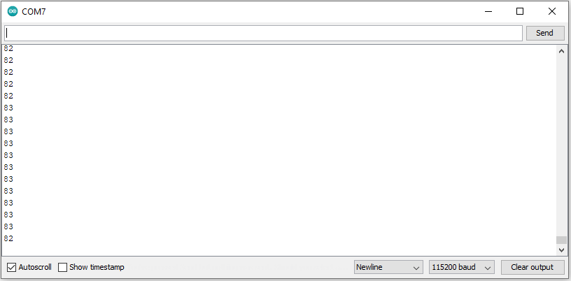
This means the Timer1 counter register has a value of 82 ticks at the beginning of the ISR handler function execution. Therefore, the measured interrupt latency = 82 / 16M = 5μs. The result is not very far from the interrupt latency seen by the INT0_ISR handler function which turned out to be 3.5μs.
Parts List
Here is the full components list for all parts that you’d need in order to perform the practical LABs mentioned here in this article and for the whole Arduino Programming series of tutorials found here on DeepBlueMbedded. Please, note that those are affiliate links and we’ll receive a small commission on your purchase at no additional cost to you, and it’d definitely support our work.
Download Attachments
You can download all attachment files for this Article/Tutorial (project files, schematics, code, etc..) using the link below. Please consider supporting my work through the various support options listed in the link down below. Every small donation helps to keep this website up and running and ultimately supports our community.
Wrap Up
To conclude this tutorial, we’d like to highlight the fact that interrupt latency is affected by a lot of factors and can be, roughly, measured by many techniques like the 2 we’ve presented in this tutorial. It becomes more important to assess the interrupt latency in systems where the CPU is receiving thousands of interrupts each second. Those few μs of interrupt latency add to the total CPU load and can’t be neglected.
If you’re just getting started with Arduino, you need to check out the Arduino Getting Started [Ultimate Guide] here.
This is the ultimate guide for getting started with Arduino for beginners. It’ll help you learn the Arduino fundamentals for Hardware & Software and understand the basics required to accelerate your learning journey with Arduino Programming.
This is the complete Arduino Interrupts Tutorial. It’ll provide you with more in-depth information about interrupts in general and specifically in Arduino, how it works, how to write efficient ISR handlers, and other tips & tricks.
