In this tutorial, you’ll learn how to do Arduino Phototransistor Interfacing and use the 3DU5C phototransistor with Arduino as a light intensity sensor. We’ll also create an Arduino Phototransistor Circuit Example Project which can be a very good starting point for your Arduino + Phototransistor project idea. Without further ado, let’s get right into it!
Table of Contents
- Arduino With Phototransistor
- Arduino Phototransistor Circuit Diagram
- Arduino Phototransistor Code Example
- Concluding Remarks
Arduino With Phototransistor
A Phototransistor is a semiconductor device that’s basically an NPN/PNP transistor but it doesn’t have a base terminal lead. Instead, the junction is exposed to ambient light that hits the base of the phototransistor which develops a small voltage across the BE junction causing the transistor to conduct (switch ON).
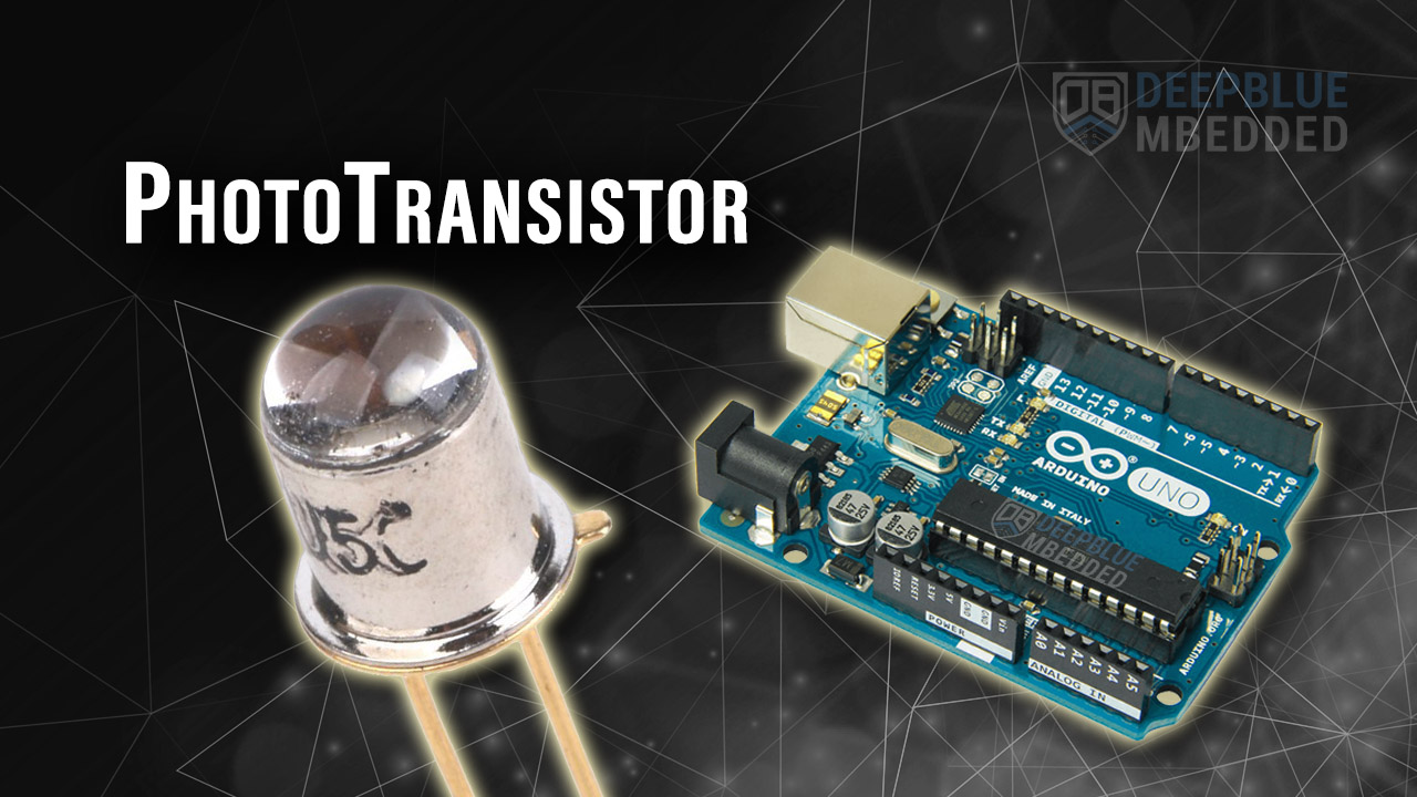
Below is the 3DU5C which is a phototransistor device that we’ll be using in this tutorial with Arduino to create a light-intensity sensor application. You can, however, use any phototransistor device available to you instead.
Note that the phototransistor’s emitter pin is the one in line with the “notch” of the body case.

Phototransistor Applications
- Solar Tracking
- Light Intensity Meters
- Position Sensing
- Photo-interrupters
- etc
Buy a Phototransistor: you can find it here on Amazon.com
Arduino Phototransistor Circuit Diagram
We need to design a simple electronic circuit to interface the phototransistor device with the Arduino microcontroller to read the output voltage developed across the phototransistor’s output load resistor when light hits it.
The easiest way to achieve this goal is to use a simple resistor between the phototransistor’s emitter & ground and read that voltage with any Arduino’s ADC analog input channel pins.
Here is the Arduino with Phototransistor circuit diagram. Note that we’re using a 1kΩ resistor here in this circuit.

Here is the equivalent circuit diagram for the Arduino phototransistor wiring diagram shown above.

Arduino Phototransistor Code Example
In this example project, we’ll use an Arduino + Phototransistor (3DU5C) as a light intensity sensor to measure the ambient light intensity. The analog voltage reading will be sent back to the PC over the serial port and we’ll display it on the serial monitor and the serial plotter.
Arduino Phototransistor Circuit Wiring
The wiring diagram for this example project is shown in the previous section, scroll up and check it out. Below is an image of how the whole setup looks like at the end, ready for the test.

Code Example
Here is the full code listing for this example.
/*
 * LAB Name: Arduino PhotoTransistor Example
 * Author: Khaled Magdy
 * For More Info Visit: www.DeepBlueMbedded.com
*/

void setup() {
  Serial.begin(9600);
}

void loop() {
  float Vout = (analogRead(A0)*5)/1023.0;
  Serial.println(Vout);
  delay(100);
}
Code Explanation
setup()
in the setup() function, we’ll initialize the serial port to operate @ 9600bps.
Serial.begin(9600);
loop()
in the loop() function, we’ll read the analog voltage on the A0 pin, convert the digital value to an analog voltage, and send it over the serial port to the PC where we’ll be monitoring it.
void loop() {
  float Vout = (analogRead(A0)*5)/1023.0;
  Serial.println(Vout);
  delay(100);
}
Arduino + Phototransistor TinkerCAD Simulation
Here is the simulation result for the phototransistor circuit on the TinkerCAD simulator. You can run it as is, or make a copy, add your own code, and start simulating to see how it’s going to behave.
You can check this simulation project on TinkerCAD using this link.
The simulation results are only for logic verification and you should not expect to get the exact same output voltage levels on the real hardware. The results may vary depending on: the resistor value you’re using, the phototransistor silicon device itself, or the light source used while testing.
In the hardware testing that I’ve done, the output voltage for the phototransistor circuit swings from 0.08v (darkness) up to 4.99v (intense light).
Required Parts List
Here is the full components list for all the parts that you’d need to perform the practical LABs mentioned here in this article and for the whole Arduino Programming series of tutorials found here on DeepBlueMbedded. Please, note that those are affiliate links and we’ll receive a small commission on your purchase at no additional cost to you, and it’d definitely support our work.
Download Attachments
You can download all attachment files for this Article/Tutorial (project files, schematics, code, etc..) using the link below. Please consider supporting my work through the various support options listed in the link down below. Every small donation helps to keep this website up and running and ultimately supports our community.
Concluding Remarks
To conclude this tutorial, we can say that you can easily interface a phototransistor with Arduino and use it as a light sensor for measuring the ambient light intensity. Try the provided example circuit on your hardware setup or at least run it in the TinkerCAD simulation environment to maximize the information gained from this tutorial.
If you’re just getting started with Arduino, you need to check out the Arduino Getting Started [Ultimate Guide] here.
And follow this Arduino Series of Tutorials to learn more about Arduino Programming.
 Circuit & Code Example")
In this tutorial, you’ll learn how to interface Arduino with a photodiode and use it for light intensity measurement as a light sensor.

This article will give more in-depth information about LDR light sensors interfacing with Arduino and how to use the LDR for light intensity measurement with Arduino.