In this tutorial, you’ll download STM32 Proteus Library For BluePill Stm32F103C6 and learn how to simulate STM32 Projects with Proteus ISIS software. We’ll also discuss some tips for STM32 Simulation to avoid running into problems while testing your projects. Without further ado, let’s get right into it!
Please, be advised that you first need to have installed Proteus ISIS on your computer and your license (time-limited free, student, or whatever) can simulate microcontroller projects (AVR, PIC, etc). I’ll show you how to install the add-on STM32 BluePill Proteus Library and use it for simulating STM32 projects.
Table of Contents
- STM32 Proteus Library
- STM32 Proteus Library Simulation Project Example
- STM32 Proteus Simulation Remarks
- Wrap Up
STM32 Proteus Library
The STM32 BluePill Proteus Library is based on the STM32 microcontroller’s ( CM3_STM32) model that comes with the Proteus ISIS simulator itself, we just need to install an add-on library to have a BluePill board that’s very similar to how a real board looks. However, you can still use the built-in STM32 library and do the essential wiring for the bare microcontroller on your own.
STM32 Proteus Library Download
You can download the STM32 BluePill Proteus Library using the link below or the button near the end of this tutorial. And unzip the folder to see its contents, and here is what’s inside.
[ Download STM32 BluePill Proteus Library Here ]

Unzip the library folder and open it, and you’ll find some folders and files. The Files I’ve marked in the screenshot above, are the model file ( .LIB and .IDX ) that we’ll copy and paste for installing the BluePill Proteus Library. Follow the next section’s step-by-step installation guide.
STM32 Proteus Library Installation
Here is a step-by-step guide for installing STM32 BluePill Proteus Library in Proteus ISIS.
1- Copy Library Files
After downloading the library folder, unzip it and copy all the ( .LIB and .IDX ) files.
2- Go to the Proteus libraries folder & Paste
Open the installation directory for proteus which is usually as follows:
C:\Program Files (x86)\Labcenter Electronics\Proteus 8 Professional\DATA\LIBRARY
And paste the files you’ve copied right there.

3- Open Proteus (ISIS) and Test
It’s now done, and you can open Proteus (ISIS) and create a new project to test the functionality of the BluePill Proteus Library. And that’s what we’ll be doing in the next section hereafter.
The Proteus BluePill library is based on the STM32F103C6 part which is the only target you can use with this board. Don’t confuse it for the BluePill with the STM32F103C8T6, though. It’s a different target MCU of the same family.
STM32 Proteus Library Simulation Project Example
In this example, we’ll test the STM32 BluePill Proteus Simulation with an LED blinking example.
(1) STM32 Proteus Simulation Project
Now, let’s create a Proteus Simulation project in ISIS (v8.13)
Open Proteus ISIS
Create New Project
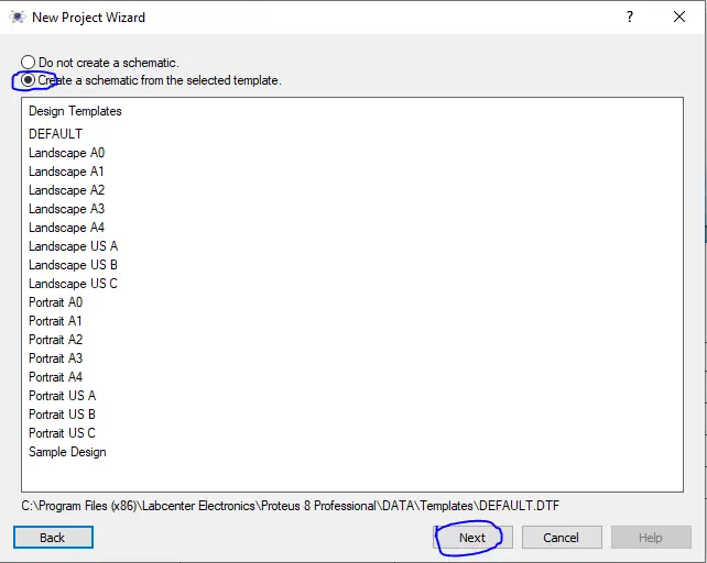
Create a Schematic With the Default Template
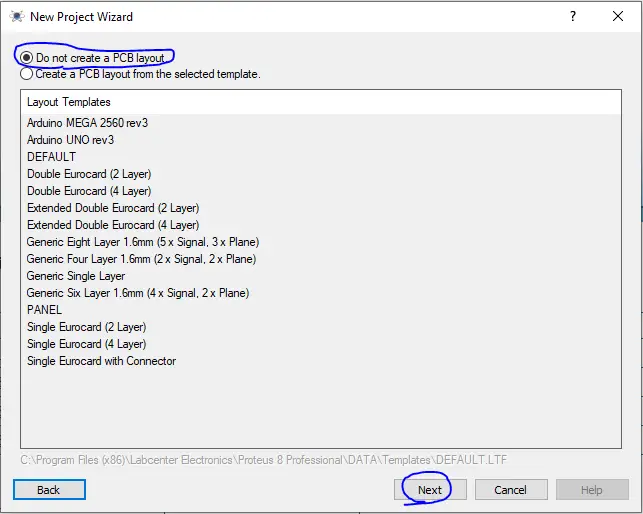
Do not create a PCB layout
No Firmware Project
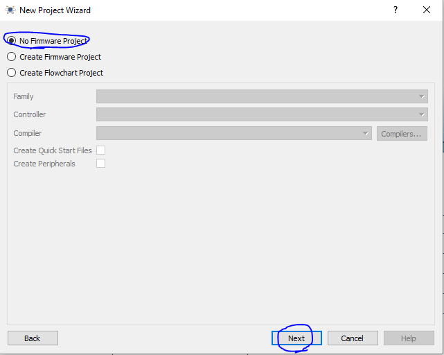
And Click Finish
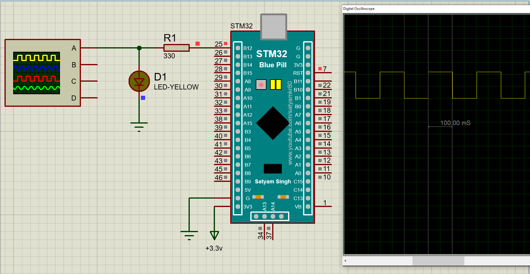
Now, we’ve created the simulation project. Let’s add the STM32 BluePill board and hook up an LED to the PB12 GPIO pin. We’ll also hook up a virtual oscilloscope to measure the toggle time to make sure the simulated microcontroller is running @ the same frequency as the real hardware.
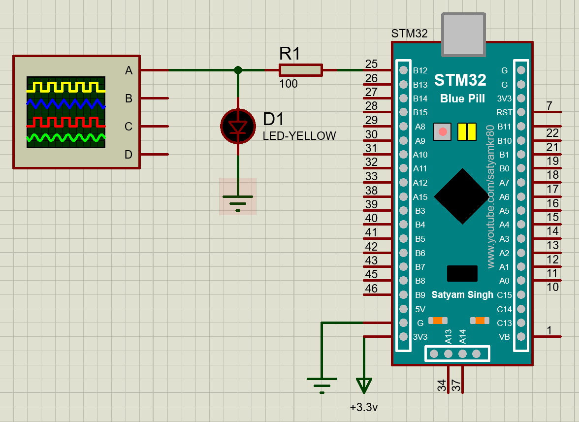
We have to connect the 3V3 pin of the BluePill board to a power label and name it +3.3v and hook up the GND power line as well. This is a must for the simulation to run without issues.
(2) STM32 LED Blink Firmware Example Project
Now, we’ll create the LED blinking firmware project for the STM32F103C6 target microcontroller in CubeMX & CubeIDE. We’ll set up the PB12 GPIO pin as an output pin and program it to toggle every 100ms and keep repeating.
Step #1
Open STM32CubeMX, create a new project, and select the STM32F103C6 target microcontroller.
Step #2
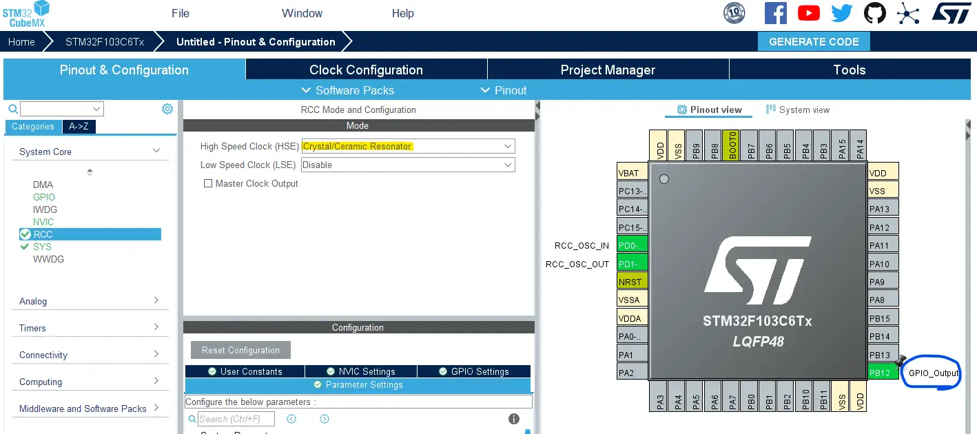
Go to the RCC clock configuration page and enable the HSE external crystal oscillator input.
Click on the PB12 GPIO pin in the “Pinout View” and select it to be in GPIO_Output mode.
Step #3
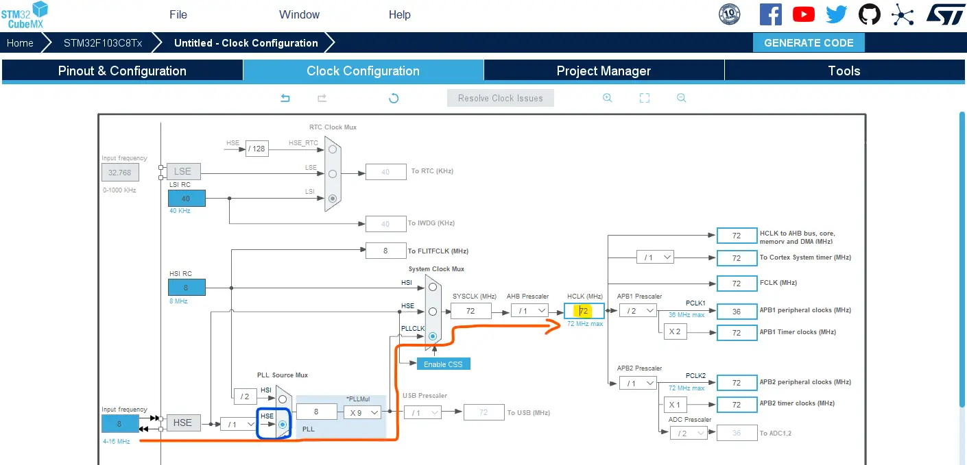
Go to the clock configurations page, and select the HSE as a clock source, PLL output, and type in 72MHz for the desired output system frequency. Hit the “ Enter” key, and let the application solve for the required PLL dividers/multipliers to achieve the desired clock rate.
The reason behind this: using the external onboard oscillator on the BluePill board provides a more accurate and stable clock, and using a 72MHz as a system clock pushes the microcontroller to its limits, so we get the maximum performance out of it. As long as we don’t care about the application’s power consumption.
Step #4
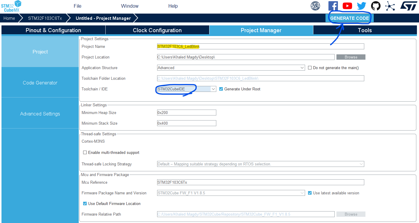
Finally, go to the Project Manager, give your project a name, select the toolchain/IDE to be STM32CubeIDE, and click on the Generate Code button.
The STM32CubeMX tool will generate the initialization code & the project main files and it’ll prompt you to open the project in STM32CubeIDE. Select, open project, and let’s move to the next step.
Step #5
Copy the following code into your main.c file replacing the auto-generated code from the beginning of the fill till the main function. You should leave everything else under the main() function in the main.c file as is.
STM32 LED Blinking Code Example
|
1 2 3 4 5 6 7 8 9 10 11 12 13 14 15 16 17 |
#include "main.h" void SystemClock_Config(void); static void MX_GPIO_Init(void); int main(void) { HAL_Init(); SystemClock_Config(); MX_GPIO_Init(); while (1) { HAL_GPIO_TogglePin (GPIOB, GPIO_PIN_12); HAL_Delay (100); } } |
Step #6
Before building the application, we need to force the compiler to generate the binary output HEX file to be used by Proteus in simulation later on.
Therefore, right-click on the project name in the project explorer and select the properties option.
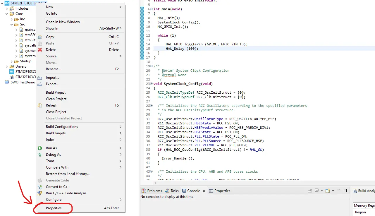
Step #7
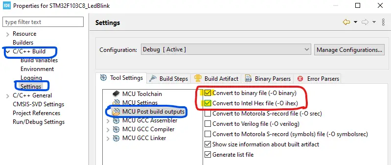
Under C/C++ Build > Settings > MCU Post build outputs
Enable HEX & BIN output formats. Only the .HEX is needed for the Proteus simulation but we can also use the binary for flashing the target later on.
Step #8
Now, click on the Build project icon to build the project and the output binary/hex files will be found in the project directory location under Debug or Release depending on the build option you’ve chosen.
(3) Running The STM32 Proteus Simulation
Having the firmware output .hex file, we’ll now add it to the Proteus simulation project that we’ve created earlier and start the simulation.
Double-click the BluePill board in the simulator, select the hex file path, and insert the actual frequency of the target MCU (which is 72MHz) in our case.
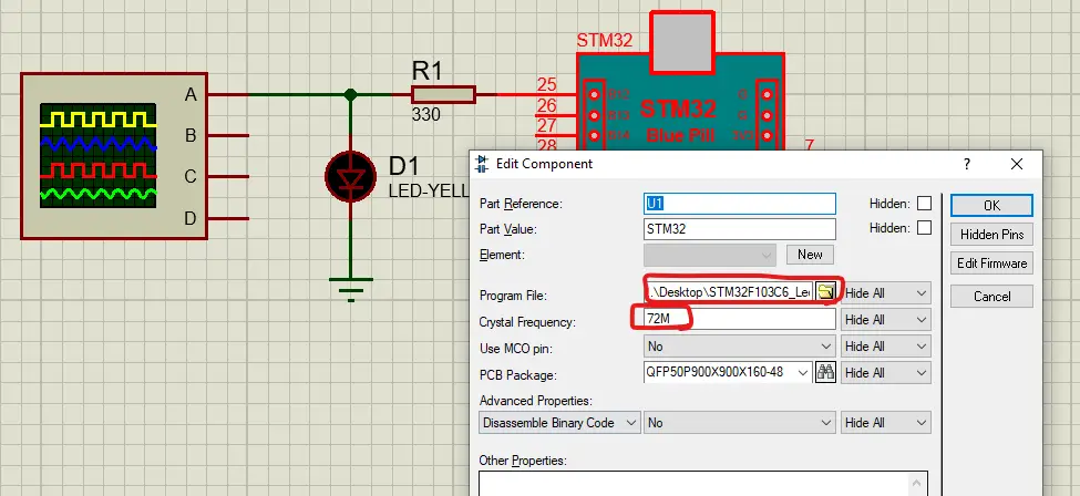
Start the simulation!
As you can see below the output waveform is exactly 100ms as we expect it to be. This indicates that the project is being simulated at the correct frequency of the target microcontroller and we can depend on the simulation environment in terms of timing behavior observation.
STM32 Proteus Simulation Remarks
Simulating your STM32 projects can be really helpful especially when you’re just getting started with STM32 microcontrollers. This step is not mandatory at all, however, running your project in a simulator environment will help you catch and fix some logic errors in the code or in the circuit wiring connections.
If the code doesn’t run logically in simulation, it won’t either do in the real world. However, the opposite is not always true. If your project runs in simulation perfectly, it doesn’t mean it’ll also do in the real world. Many external factors can affect the application running on a real STM32 board. Things like noise, bad wiring, damaged parts, and more other obstacles that can’t be predicted by your simulator.
Moreover, the simulation environment will have its own limitations at the end of the day. It’s going to have a limited number of modules and sensors to use with STM32, only a couple of STM32 microcontrollers are included, insufficient measurement tools, and many other limitations.
Also, pay attention to the warning messages that Proteus displays at the bottom of the screen. Always click on it and see what’s going on. It’ll give you a great notification for catastrophic events such as:
- Power Reset
- Watchdog Reset
- Excessive current or voltage
- Wrong or missing circuit connections
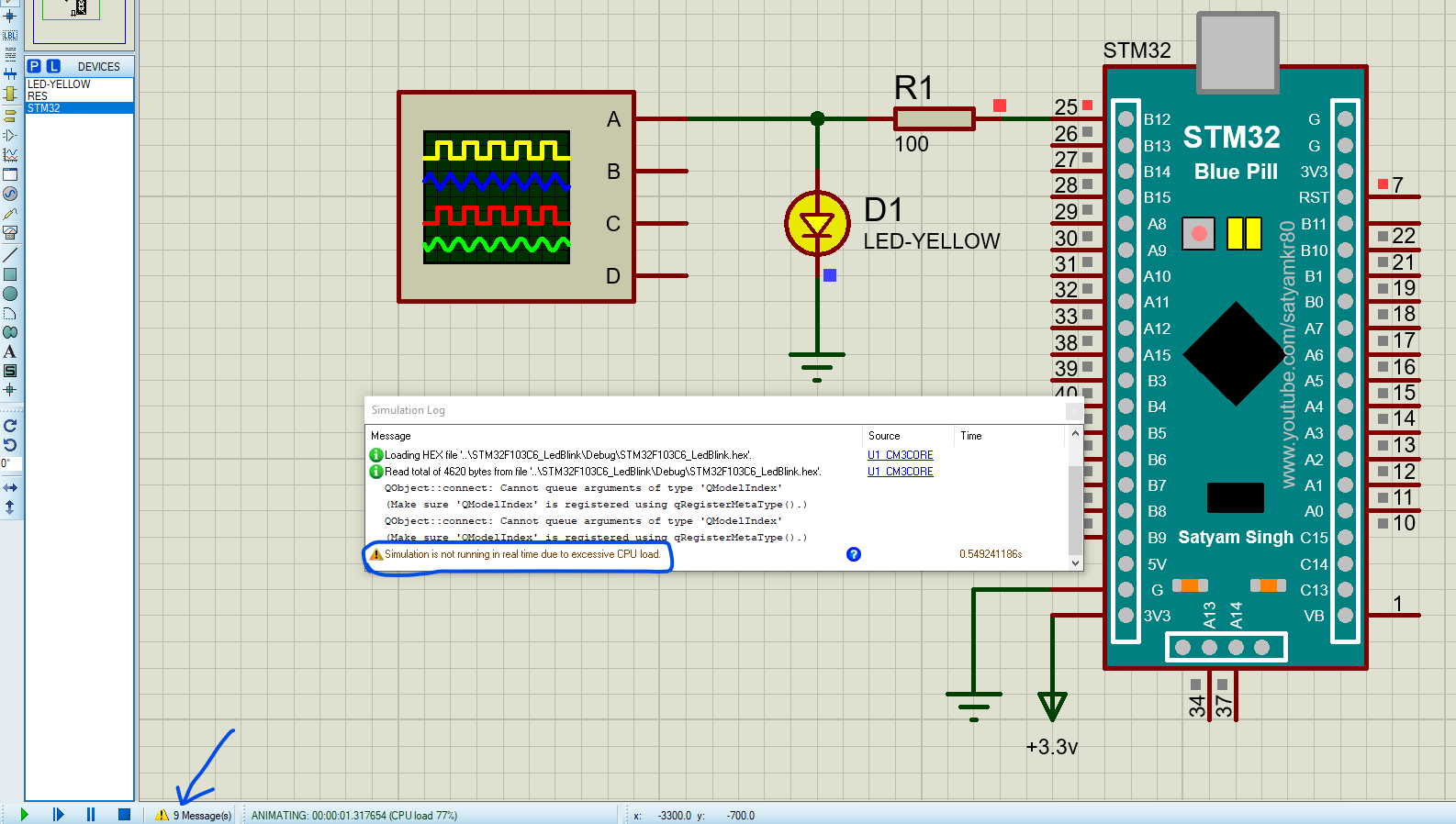
And it’s going to warn you if the simulation is not running in real time. This means you shouldn’t care too much about any timing behavior you’ll see in the simulation screen like LED blinking time and such. It’s going to take longer than programmed due to excessive CPU loading during simulation, don’t change your code to accommodate for it. It’s a simulation runtime issue not in your STM32 code itself.
But all in all, it’s a great tool for learning and getting started with STM32 even if you don’t have an STM32 board or the full hardware kit yet.
Download Attachments
You can download all attachment files for this Article/Tutorial (project files, schematics, code, etc..) using the link below. Please consider supporting my work through the various support options listed in the link below. Every small donation helps to keep this website up and running and ultimately supports our community.
Wrap Up
To conclude this tutorial, I’d like to highlight the fact that only STM32F103C6 target microcontroller is supported by the BluePill Proteus library. By following the steps illustrated earlier in this tutorial, you’ll be able to set up the STM32 BluePill Proteus simulation library and run your STM32 firmware projects inside the Proteus ISIS simulator.
If you’re just getting started with STM32, you need to check out the STM32 Getting Started Tutorial here.
Follow this STM32 Series of Tutorials to learn more about STM32 Microcontrollers Programming.
