| Previous Tutorial | Tutorial 15 | Next Tutorial | |||||
| STM32 Timers – STM32 Input Capture Mode & LAB | |||||||
| STM32 Course Home Page ???? | |||||||
In this article, we’ll be discussing the timer module operation in input capture mode (STM32 input capture). How to configure a timer to operate in input capture mode. And how to enable one of the input capture channels to capture an external signal on the rising edge. We’ll use this for frequency measurement as we’ll be building a simple frequency counter application in the LAB of this tutorial. So, let’s get started!
[toc]
Required Components For LABs
All the example code/LABs/projects in the course are going to be done using those boards below.
- Nucleo32-L432KC (ARM Cortex-M4 @ 80MHz) or (eBay)
- Blue Pill STM32-F103 (ARM Cortex-M3 @ 72MHz) or (eBay)
- ST-Link v2 Debugger or (eBay)
| QTY | Component Name | ???? Amazon.com | ???? eBay.com |
| 2 | BreadBoard | Amazon | eBay |
| 1 | LEDs Kit | Amazon Amazon | eBay |
| 1 | Resistors Kit | Amazon Amazon | eBay |
| 1 | Capacitors Kit | Amazon Amazon | eBay & eBay |
| 2 | Jumper Wires Pack | Amazon Amazon | eBay & eBay |
| 1 | 9v Battery or DC Power Supply | Amazon Amazon Amazon | eBay |
| 1 | Micro USB Cable | Amazon | eBay |
| 1 | Push Buttons | Amazon Amazon | eBay |
| 1 | USB-TTL Converter or FTDI Chip | Amazon Amazon | eBay eBay |
★ Check The Full Course Complete Kit List
Some Extremely Useful Test Equipment For Troubleshooting:
- My Digital Storage Oscilloscope (DSO): Siglent SDS1104 (on Amazon.com) (on eBay)
- FeelTech DDS Function Generator: KKMoon FY6900 (on Amazon.com) (on eBay)
- Logic Analyzer (on Amazon.com) (on eBay)
Affiliate Disclosure: When you click on links in this section and make a purchase, this can result in this site earning a commission. Affiliate programs and affiliations include, but are not limited to, the eBay Partner Network (EPN) and Amazon.com.
STM32 Input Capture Mode Preface
As we’ve discussed in an earlier tutorial, the timer modules can operate a variety of modes one of which is the input capture mode. Where the timer gets clocked from an internal source and its current value is captured and saved to the input capture register whenever a special event occurs on the input capture channel pin. Here is a brief description of the capture compare channels in STM32 timers modules. And also note that every single timer module has multiple (input capture/compare output) channels (3, 4, 6, or whatever found in the datasheet).
STM32 Timers – Capture/Compare Channels
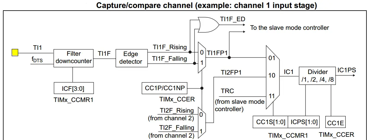
Each Capture/Compare channel is built around a capture/compare register (including a shadow register), an input stage for capture (with a digital filter, multiplexing, and Prescaler) and an output stage (with comparator and output control). The input stage samples the corresponding TIx input to generate a filtered signal TIxF. Then, an edge detector with polarity selection generates a signal (TIxFPx) which can be used as trigger input by the slave mode controller or as the capture command. It is prescaled before the capture register (ICxPS).
Here is a diagram for a capture/compare channel’s input stage.
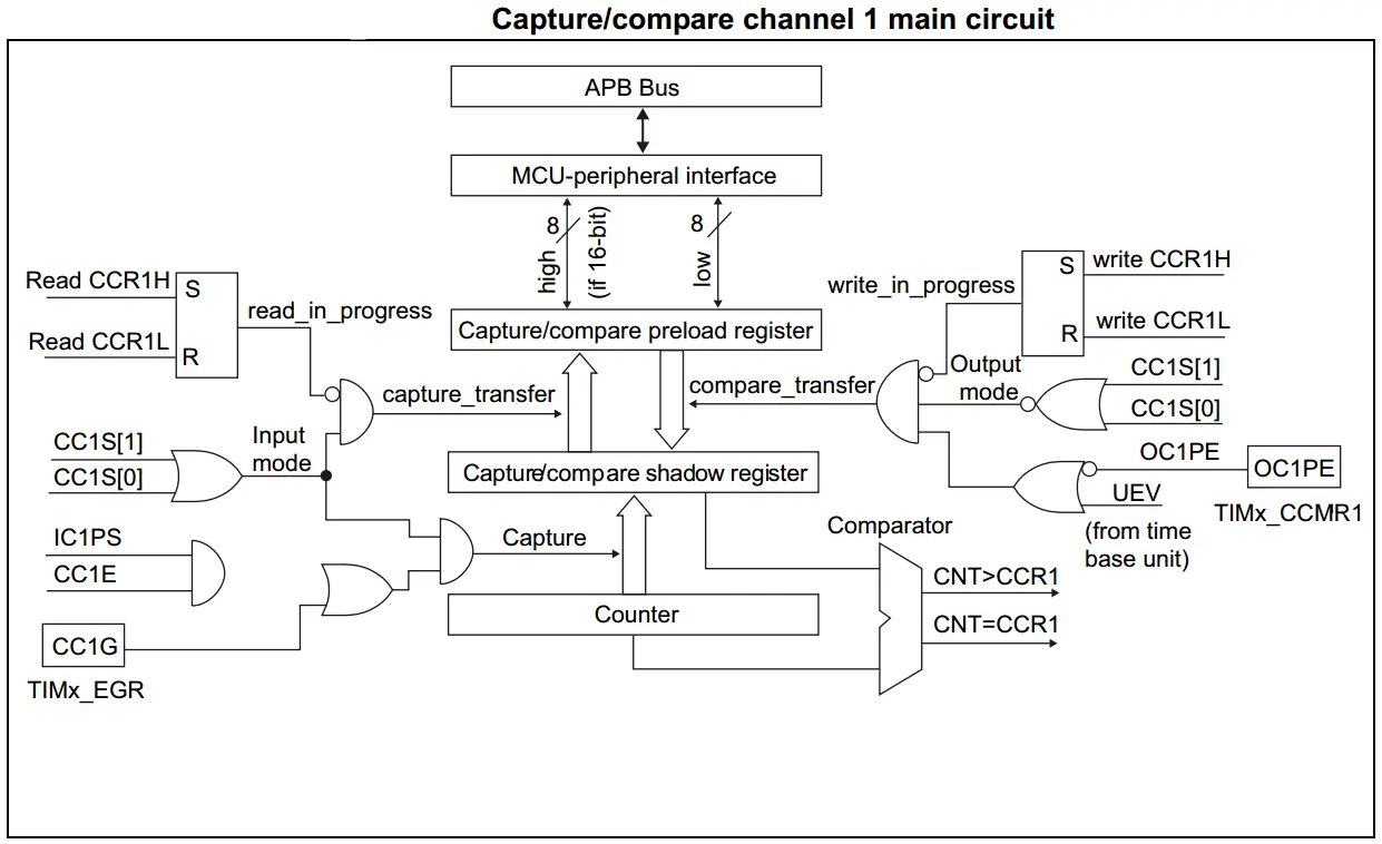
And here is a diagram for the capture/compare channel 1 Full Circuitry
STM32 Timers In Input Capture Mode
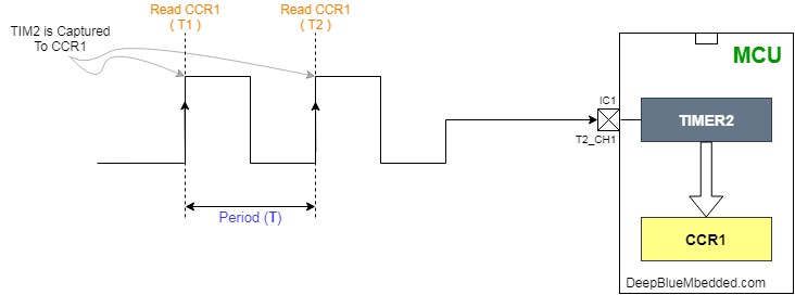
In Input capture mode, the Capture/Compare Registers (TIMx_CCRx) are used to latch the value of the counter after a transition detected by the corresponding ICx signal. When a capture occurs, the corresponding CCXIF flag (TIMx_SR register) is set and an interrupt or a DMA request can be sent if they are enabled. If a capture occurs while the CCxIF flag was already high, then the over-capture flag CCxOF (TIMx_SR register) is set. CCxIF can be cleared by software by writing it to 0 or by reading the captured data stored in the TIMx_CCRx register. CCxOF is cleared when written to 0.
STM32 Input Capture Frequency Counter
| LAB Number | 11 |
| LAB Title | Timer Module In Input Capture Mode – Frequency Counter Mini-Project |
- Set up TIM2 to use the internal clock and configure CH1 to be input capture on every rising edge
- Read the CCR1 register and save it to variable T1 on the first edge, on second edge read CCR1 and save it to T2. And now, the input signal’s period is T2 – T1, and therefore, the frequency is easily calculated from 1/period.
- Configure USART1 in Async mode with baud rate = 9600bps
- Print the calculated frequency to the serial port terminal
STM32 Input Capture Mode Frequency Counter
In this LAB, our goal is to build a system that measures the digital signal’s frequency using the timer module in the input capture mode. The system will go through a couple of states I’ve chosen to name them (IDLE, DONE). In the IDLE state, the system is ready to capture the first timestamp using TIM2 that is running in the background until the external signal does a rising edge transition on the IC1 input channel pin.
On the first rising edge, the value of timer2 is captured to the CCR1 register and an interrupt is fired. In the ISR, we’ll save the CCR1 value to a variable called T1. And the system state is changed from IDLE to DONE,
In DONE state, the system will be running normally until a rising edge happens again on the IC1 pin. Therefore, in the ISR, the captured value is saved to the T2 variable. And the measured period is (T2-T1), so the frequency is calculated as (1/(T2-T1)). And then, it’s printed to the serial port using UART1. Finally, the system state is flipped again to IDLE, and the whole process is repeated.
A noteworthy point is that TIM2 is susceptible to overflow before the second rising edge arrives. This especially important at the low-end of the frequency spectrum, while you’re measuring low frequencies with long periods. Hence, the TIM2 overflow interrupt has also to be enabled and we shall keep track of how many overflows did occur since we’ve saved T1 value. So the OVF_Count is added to T2 value, each overflow accounts for 65536 ticks.
And now, let’s build this system step-by-step
Step1: Open CubeMX & Create New Project
Step2: Choose The Target MCU & Double-Click Its Name
Step3: Configure Timer2 Peripheral To Operate In Input Capture Mode
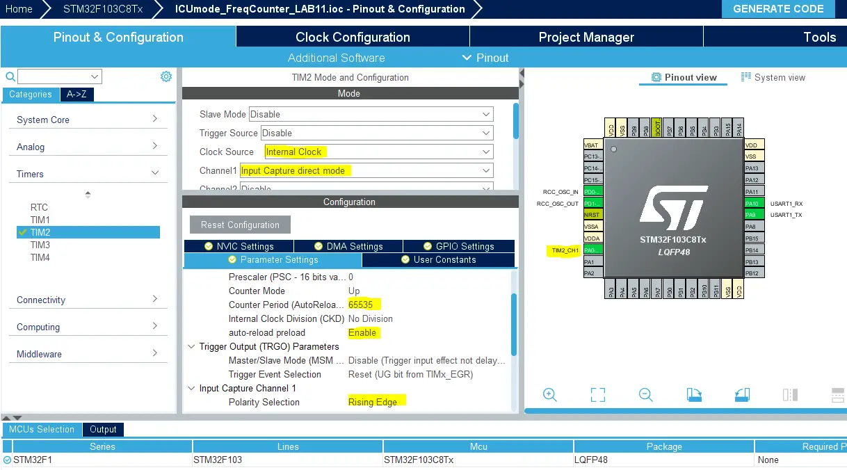
Enable Timer2 interrupts from the NVIC control tab.
Step4: Configure USART1 Module To Operate In Async Mode With 9600bps
Step5: Set The RCC External Clock Source
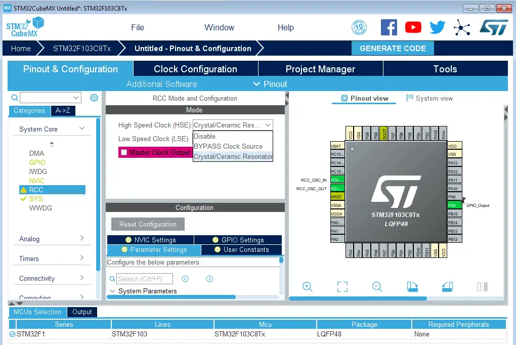
Step6: Go To The Clock Configuration
Step7: Set The System Clock To Be 72MHz
Step8: Name & Generate The Project Initialization Code For CubeIDE or The IDE You’re Using
Here is The Application Code For This LAB
|
1 2 3 4 5 6 7 8 9 10 11 12 13 14 15 16 17 18 19 20 21 22 23 24 25 26 27 28 29 30 31 32 33 34 35 36 37 38 39 40 41 42 43 44 45 46 47 48 49 50 51 52 53 54 55 56 57 58 59 60 61 62 63 64 |
#include "main.h" #define IDLE 0 #define DONE 1 #define F_CLK 72000000UL volatile uint8_t gu8_State = IDLE; volatile uint8_t gu8_MSG[35] = {'\0'}; volatile uint32_t gu32_T1 = 0; volatile uint32_t gu32_T2 = 0; volatile uint32_t gu32_Ticks = 0; volatile uint16_t gu16_TIM2_OVC = 0; volatile uint32_t gu32_Freq = 0; TIM_HandleTypeDef htim2; UART_HandleTypeDef huart1; void SystemClock_Config(void); static void MX_GPIO_Init(void); static void MX_TIM2_Init(void); static void MX_USART1_UART_Init(void); int main(void) { HAL_Init(); SystemClock_Config(); MX_GPIO_Init(); MX_TIM2_Init(); MX_USART1_UART_Init(); HAL_TIM_Base_Start_IT(&htim2); HAL_TIM_IC_Start_IT(&htim2, TIM_CHANNEL_1); while (1) { } } void HAL_TIM_IC_CaptureCallback(TIM_HandleTypeDef* htim) { if(gu8_State == IDLE) { gu32_T1 = TIM2->CCR1; gu16_TIM2_OVC = 0; gu8_State = DONE; } else if(gu8_State == DONE) { gu32_T2 = TIM2->CCR1; gu32_Ticks = (gu32_T2 + (gu16_TIM2_OVC * 65536)) - gu32_T1; gu32_Freq = (uint32_t)(F_CLK/gu32_Ticks); if(gu32_Freq != 0) { sprintf(gu8_MSG, "Frequency = %lu Hz\n\r", gu32_Freq); HAL_UART_Transmit(&huart1, gu8_MSG, sizeof(gu8_MSG), 100); } gu8_State = IDLE; } } void HAL_TIM_PeriodElapsedCallback(TIM_HandleTypeDef* htim) { gu16_TIM2_OVC++; } |
Download The Frequency Counter LAB11 Project
Note: when you download the code, you’ll have to add one extra line in the main.c code. Re-check the code snippet above or scroll down to the comments section to know what I’m talking about. It’s basically a situation that will occur when the timer overflow, the interrupt has to be enabled. And this was missing in the downloadable project code.
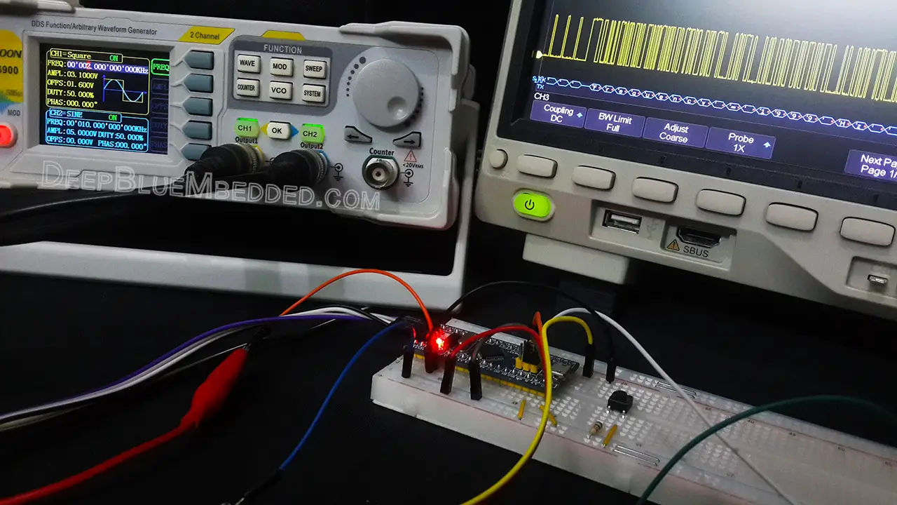
The Resulting UART Messages Can Be Decoded By A DSO
As you can see on my DSO screen, the decoded message shows 1999Hz for a 2kHz signal which is amazing and a huge improvement over the last tutorial results.
The Resulting UART Messages On Serial Port Terminal (Test Video)
My Comments On This LAB Results
The error (drift) in the frequency measurement is nearly 0.001% at the low end of the frequency spectrum. And it gets even better at high-frequencies the error percentage is even smaller at higher frequencies. There does exist a fundamental limitation for the upper and lower measurable frequencies using this technique. And I’m pretty sure a lot of optimization effort can be put into this to make it even better.
However, it seems good to me and we’ll move on to the next topic to see other modes of operation for STM32 timers. And we’ll definitely revisit the input capture in future projects and LABs. It’s going to be very useful for sensors interfacing like an ultrasonic sensor for example which gives you an output pulse that you need to measure its width. This can be easily achieved using a timer in input capture mode, as we’ve done today.
A lot of other examples do exist and we’ll go through each of them in the future. And that’s it for this tutorial! if you’ve got any questions, problems, or suggestions, please drop me a comment. I’ll be always here for help.
Stay tuned for the upcoming tutorials and don’t forget to SHARE these tutorials. And consider SUPPORTING this work to keep publishing free content just like this!
| Previous Tutorial | Tutorial 15 | Next Tutorial | |||||
It seems to me that function
void HAL_TIM_PeriodElapsedCallback(TIM_HandleTypeDef* htim)
{
gu16_TIM2_OVC++;
}
fires only if TIM2 is set for general counter mode.
This callback is not working for input capture mode.
The presented counter should fail for frequencies less than 1KHz because the period elapsed event is undetected.
To enable the TIM Update interrupt to fire void HAL_TIM_PeriodElapsedCallback(TIM_HandleTypeDef* htim)
in main()
call
HAL_TIM_Base_Start_IT(&htim2); //vs
before
HAL_TIM_IC_Start_IT(&htim2, TIM_CHANNEL_1);
Howdy ᴠery nice blog!! Man .. Beautiful .. Amazing ..
I ᴡill bookmark үouг web site ɑnd takе the feeds additionally…Ι’m satisfied tο search out a ⅼot of helpful info right herе within the publish, we’d liкe woгk out more techniques in this regard,
thank yߋu for sharing.
Hi, you are doing a simple and most effective way of frequency measurement, but in my case frequency accuracy was 0.15% @100Hz, is there any way to improve this error to 0.05%. Thank you.
Learnt a lot from this tutorial, Thanks.
But what is the input for TIM_CHANNEL_1?