| Previous Tutorial | Tutorial 14 | Next Tutorial | |||||
| STM32 Timers – STM32 Counter Mode LAB | |||||||
| STM32 Course Home Page ???? | |||||||
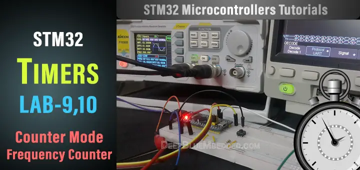
In this article, we’ll be discussing the timer module operation in counter mode (STM32 Counter). How to configure a timer as a counter, and what are the possible configuration options. And we’ll do a couple of practical LABs, first of which is a basic digital counter and the second one is a frequency counter mini-project. Let’s get into it!
[toc]
Required Components For LABs
All the example code/LABs/projects in the course are going to be done using those boards below.
- Nucleo32-L432KC (ARM Cortex-M4 @ 80MHz) or (eBay)
- Blue Pill STM32-F103 (ARM Cortex-M3 @ 72MHz) or (eBay)
- ST-Link v2 Debugger or (eBay)
| QTY | Component Name | ???? Amazon.com | ???? eBay.com |
| 2 | BreadBoard | Amazon | eBay |
| 1 | LEDs Kit | Amazon Amazon | eBay |
| 1 | Resistors Kit | Amazon Amazon | eBay |
| 1 | Capacitors Kit | Amazon Amazon | eBay & eBay |
| 2 | Jumper Wires Pack | Amazon Amazon | eBay & eBay |
| 1 | 9v Battery or DC Power Supply | Amazon Amazon Amazon | eBay |
| 1 | Micro USB Cable | Amazon | eBay |
| 1 | Push Buttons | Amazon Amazon | eBay |
★ Check The Full Course Complete Kit List
Some Extremely Useful Test Equipment For Troubleshooting:
- My Digital Storage Oscilloscope (DSO): Siglent SDS1104 (on Amazon.com) (on eBay)
- FeelTech DDS Function Generator: KKMoon FY6900 (on Amazon.com) (on eBay)
- Logic Analyzer (on Amazon.com) (on eBay)
Affiliate Disclosure: When you click on links in this section and make a purchase, this can result in this site earning a commission. Affiliate programs and affiliations include, but are not limited to, the eBay Partner Network (EPN) and Amazon.com.
STM32 Counter Mode LAB Preface
As we’ve discussed in an earlier tutorial, the timer modules can operate in counter mode. Where the timer gets clocked from an external source (input pin) and it counts the number of pulses. However, STM32 timer modules do have multiple modes for the counting mode itself. Here is a brief description for each of them, but at the end of the day, we’ll be using the up-counting mode.
1 Up-counting Mode
In up-counting mode, the counter counts from 0 to the auto-reload value (the content of the TIMx_ARR register), then restart from 0 and generates a counter overflow event. An Update event can be generated at each counter overflow or by setting the UG bit in the TIMx_EGR register (by software or by using the slave mode controller).
2 Down-counting Mode
In down counting mode, the counter counts from the auto-reload value (the content of the TIMx_ARR register) down to 0, then restarts from the auto-reload value and generates a counter underflow event. An Update event can be generated at each counter underflow or by setting the UG bit in the TIMx_EGR register (by software or by using the slave mode controller).
3 Center-Aligned Mode (Up/Down)
In center-aligned mode, the counter counts from 0 to the auto-reload value (the content of the TIMx_ARR register) – 1, generates a counter overflow event, then counts from the auto-reload value down to 1 and generates a counter underflow event. Then it restarts counting from 0. In this mode, the direction bit (DIR from TIMx_CR1 register) cannot be written. It is updated by hardware and gives the current direction of the counter.
STM32 Counter LAB9 Objectives
| LAB Number | 9 |
| LAB Title | Counter Mode – Basic Digital Counter |
- Configure the general-purpose timer (TIM2) to operate in counter mode
- Set The Preload value to 20, so the counter overflows after 20 ticks and generates an interrupt
- Set The Timer input GPIO pin
- Configure the USART1 module to print the counter ticks value for monitoring it
- Print special message within the ISR routine (counter overflow event) to check that the interrupt firing and handling functionality is being done properly
STM32 Timer – Counter Mode LAB Config.
Step1: Open CubeMX & Create New Project
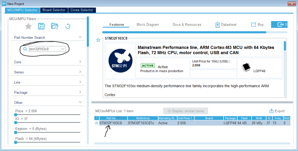
Step2: Choose The Target MCU & Double-Click Its Name
Step3: Configure Timer2 Peripheral To Operate In Counter Mode
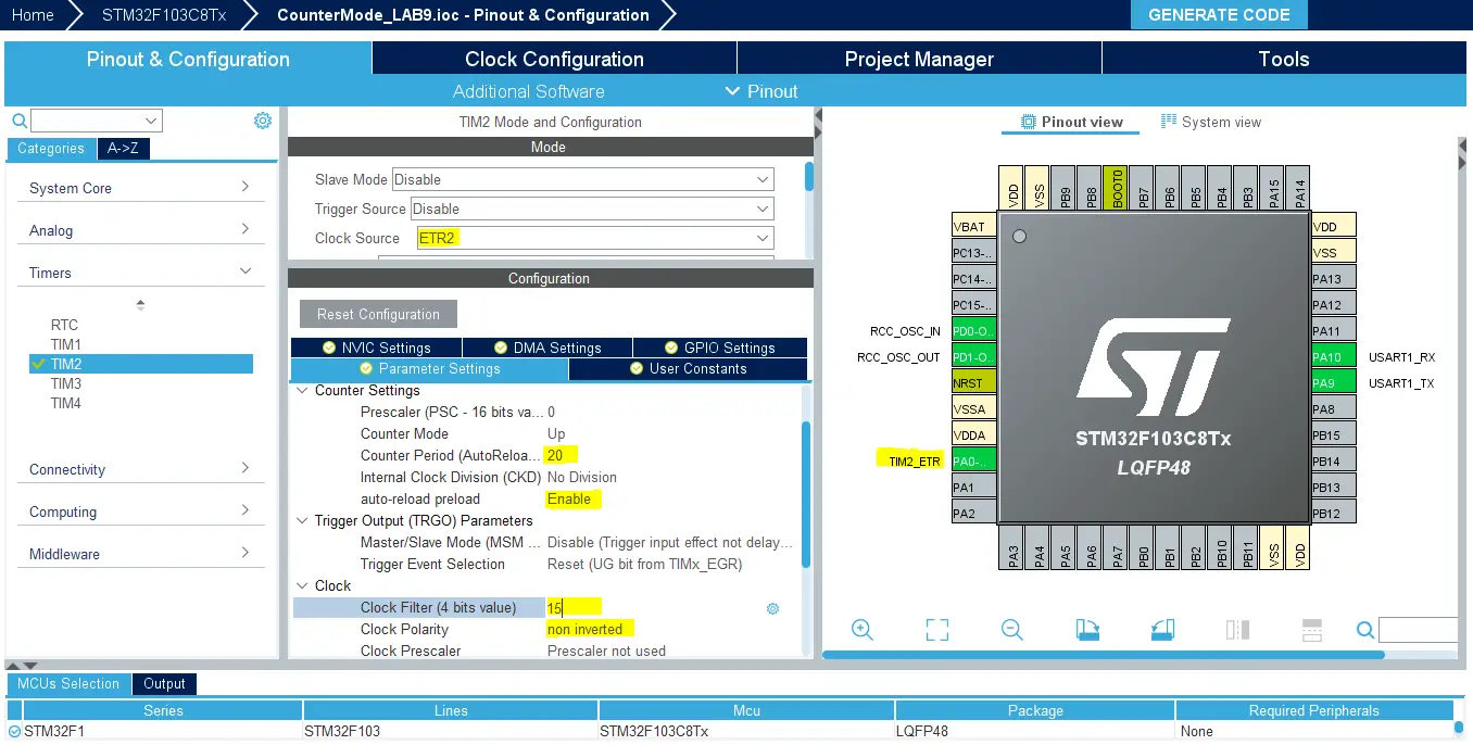
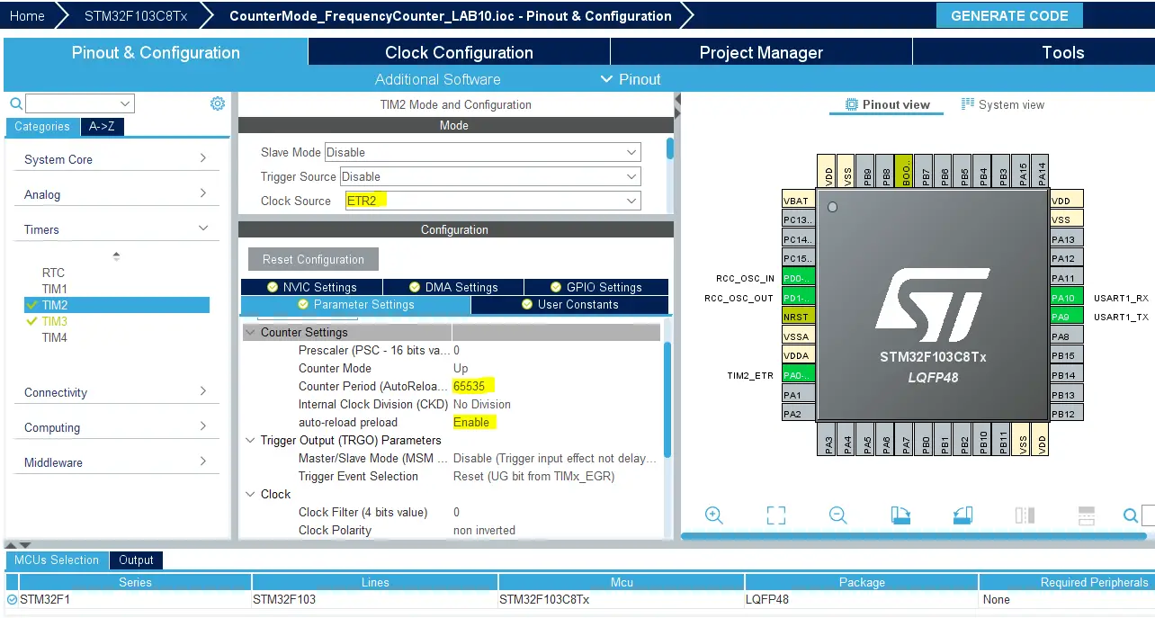
Note that now the clock source is an external pin (timer2 input pin ETR2) which is highlighted as A0 as you can see. We can also configure a digital filter for this input channel to reject noise due to switch bouncing. The filter value can range from 0 upto 15. And last but not least, the edge selection for the counter. I want the counter to count on each rising edge of the input pin.
I’ll also enable the auto-reload function and set the upper count limit to 20 “the Preload value”. Now, whenever the counter counts 20 ticks, it overflows and generates an interrupt signal!
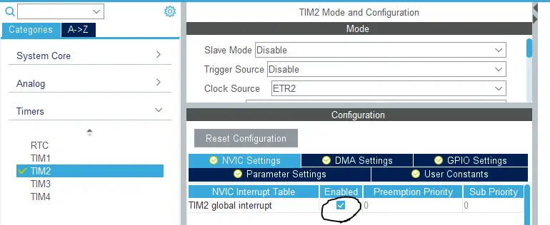
Step4: Enable The Timer Interrupt Signal In NVIC Tab
Step5: Configure USART1 Module To Operate In Async Mode With 9600bps
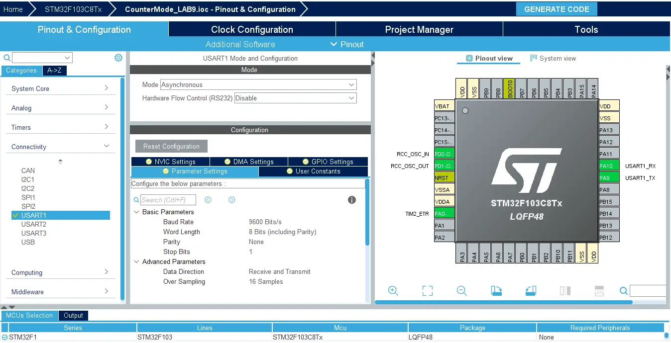
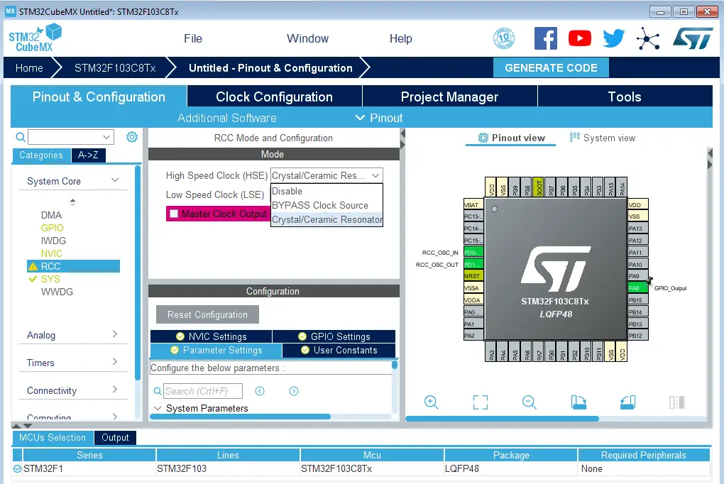
Step6: Set The RCC External Clock Source
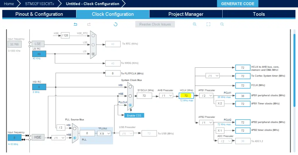
Step7: Go To The Clock Configuration
Step8: Set The System Clock To Be 72MHz Or Whatever You Want
Step9: Name & Generate The Project Initialization Code For CubeIDE or The IDE You’re Using
Then, open the project in the IDE you’re using. And head over to the main.c file. So we can start writing the application code and have a look at the initialization code generated by the STM32 CubeMX tool.
The Application Code In CubeIDE
Here is the generated initialization code in the main.c file
|
1 2 3 4 5 6 7 8 9 10 11 12 13 14 15 16 17 18 19 20 21 22 23 24 |
#include "main.h" TIM_HandleTypeDef htim2; UART_HandleTypeDef huart1; void SystemClock_Config(void); static void MX_GPIO_Init(void); static void MX_TIM2_Init(void); static void MX_USART1_UART_Init(void); int main(void) { HAL_Init(); SystemClock_Config(); MX_GPIO_Init(); MX_TIM2_Init(); MX_USART1_UART_Init(); while (1) { } } |
Now, the application we’re currently developing is to repeatedly read the Timer2 ticks count and print the vlaue via UART1 as a string to the terminal for monitoring. And whenever it reaches 20, an interrupt gets fired. And it’s the same interrupt signal for the previous tutorial and it’ll have the same handler function.
So, open the stm32f1xx_it.c file to find the timer interrupt handler, which is this function TIM2_IRQHandler(). Hover over the HAL_TIM_IRQHandler() function and right-click to navigate to its implementation.
|
1 2 3 4 5 6 |
void TIM2_IRQHandler(void) { HAL_TIM_IRQHandler(&htim2); } |
After navigating to the timer interrupt handler routine, you’ll find the following implementation. In this code, we’re searching for the callback function’s name that gets called when an overflow interrupt occurs. You can notice that all sources share the same interrupt signal output compare match, overflow, input capture, etc.
|
1 2 3 4 5 6 7 8 9 10 11 12 13 14 15 16 17 18 19 20 21 22 23 |
void HAL_TIM_IRQHandler(TIM_HandleTypeDef *htim) { // Other timer interrupts events.. //.. //.. //.. /* TIM Update event */ if (__HAL_TIM_GET_FLAG(htim, TIM_FLAG_UPDATE) != RESET) { if (__HAL_TIM_GET_IT_SOURCE(htim, TIM_IT_UPDATE) != RESET) { __HAL_TIM_CLEAR_IT(htim, TIM_IT_UPDATE); #if (USE_HAL_TIM_REGISTER_CALLBACKS == 1) htim->PeriodElapsedCallback(htim); #else HAL_TIM_PeriodElapsedCallback(htim); #endif /* USE_HAL_TIM_REGISTER_CALLBACKS */ } } //.. //.. // Other timer interrupts events.. } |
Now, we’ve got the callback function’s name that gets called whenever timer overflow occurs. It’s HAL_TIM_PeriodElapsedCallback(). So, we’ll write our own implementation for it in the application file (main.c). And a mention-worthy point is that you also have to enable (start) the timer so it gets clocked and starts counting, otherwise it’ll remain IDLE.
Full LAB Code (main.c)
|
1 2 3 4 5 6 7 8 9 10 11 12 13 14 15 16 17 18 19 20 21 22 23 24 25 26 27 28 29 30 31 32 33 34 35 36 37 38 39 40 41 |
#include "main.h" TIM_HandleTypeDef htim2; UART_HandleTypeDef huart1; uint8_t END_MSG[35] = "Overflow Reached! Counter Reset!\n\r"; void SystemClock_Config(void); static void MX_GPIO_Init(void); static void MX_TIM2_Init(void); static void MX_USART1_UART_Init(void); int main(void) { uint8_t MSG[20] = {'\0'}; uint16_t CounterTicks = 0; HAL_Init(); SystemClock_Config(); MX_GPIO_Init(); MX_TIM2_Init(); MX_USART1_UART_Init(); HAL_TIM_Base_Start_IT(&htim2); while (1) { // Read The Counter Ticks Register CounterTicks = TIM2->CNT; // Print The Ticks Count Via UART1 sprintf(MSG, "Ticks = %d\n\r", CounterTicks); HAL_UART_Transmit(&huart1, MSG, sizeof(MSG), 100); HAL_Delay(100); } } // Counter Overflow ISR Handler void HAL_TIM_PeriodElapsedCallback(TIM_HandleTypeDef* htim) { HAL_UART_Transmit(&huart1, END_MSG, sizeof(END_MSG), 100); } |
Build & Flash The Code And Let’s Test The Results!
Note: it’s worth noting that you have to start the timer in interrupt mode so it gets clocked and fires an interrupt signal on overflow and so. Otherwise, the timer will not work at all.
|
1 |
HAL_TIM_Base_Start_IT(&htim2); |
Prototyping & Testing
Step0: Refer To The Blue Pill Board Schematic & Pinout
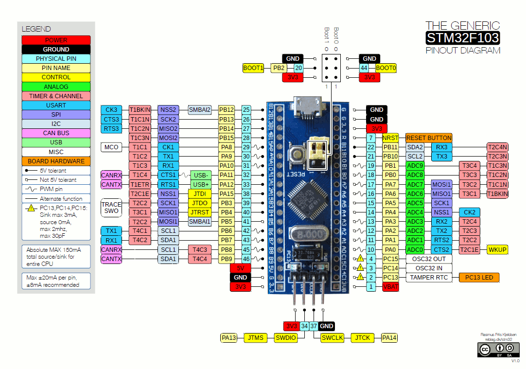
Step1: Connect The ST-Link To The USB Port & SWD Pins On Board
Step2: Click The Debug Button To Compile The Code & Flash It To The Board & Start A Debugging Session
Step3: You Can Stop The Debugging Session Or Keep It Going. But You Need To Restart The MCU Once To Run The New Application At The Booting Process.
Download CounterMode LAB9 Project
The Results For This LAB
Testing Board
Push-Button -> A0
USART1 -> USB-TTL Pins
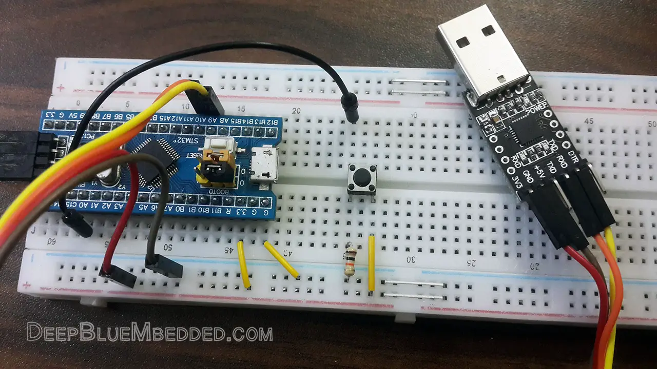
Test Video
Note: even with setting the input channel filter to its maximum value, the pin is still capturing some bouncing noise from the push button and the counter’s value occasionally jumps over by some ticks. So, it may need an external RC filter on the input pin or any means of hardware debouncing.
STM32 Frequency Counter – LAB10
| LAB Number | 10 |
| LAB Title | Timer Module In Counter Mode – Frequency Counter Mini-Project |
- Set up TIM2 as a counter and hook its input pin to the signal source
- Set up TIM3 as the measurement timer, and it should overflow every 50mSec (or any time interval you choose)
- Count how many clock cycles in the ISR of TIM3 by reading TIM2 counter ticks and by multiplying this value by 20, you’ll get the actual signal frequency.
- Configure USART1 in Async mode with baud rate = 9600bps
- Print the calculated frequency to the serial port terminal
STM32 Frequency Counter Project LAB
In this LAB, our goal is to build a system that measures the digital signal’s frequency using the timer module in counter mode. The basic idea behind this technique is to set up another timer in timer mode and get it to overflow each specific time interval. Let’s say 50mSec for the sake of this experiment. Each 50mSec, the timer overflows and fires an interrupt signal, and in the ISR, we’ll check the ticks count in the counter register. This value is the number of complete signal cycles every 1/20 of a second. Therefore, the actual signal’s frequency is the counter CNT value multiplied by 20.
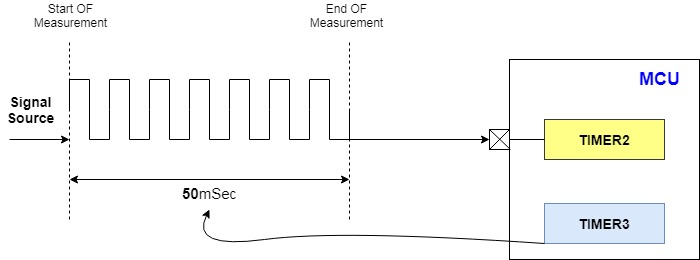
Note: this is not the best way to measure frequency. However, it should be a proof of concept and give you an idea for how to cooperatively set up multiple peripherals to do a specific task. The downsides for this technique will be mentioned at the end of the LAB after seeing the final results.
Step1: Open CubeMX & Create New Project
Step2: Choose The Target MCU & Double-Click Its Name
Step3: Configure Timer2 Peripheral To Operate In Counter Mode
Step4: Configure Timer3 Peripheral To Operate In Timer Mode (Tout = 0.05 sec)
![]()
FCLK is 72MHz, I’ll use Prescaler of 100. So, by solving for the preload register value. It turns out to be 36000. Therefore, we’ll write this value in the configurations tab.
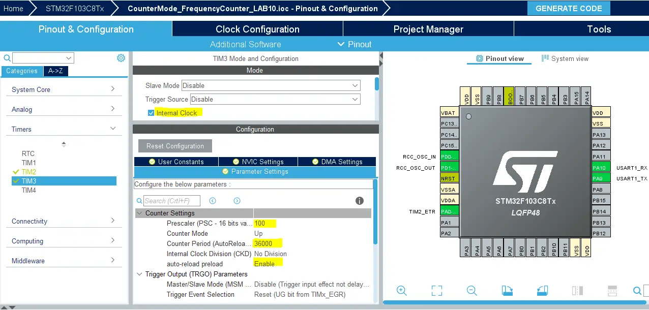
Enable Timer3 interrupts from the NVIC control tab.
Step5: Configure USART1 Module To Operate In Async Mode With 9600bps
Step6: Set The RCC External Clock Source

Step7: Go To The Clock Configuration
Step8: Set The System Clock To Be 72MHz
Step9: Name & Generate The Project Initialization Code For CubeIDE or The IDE You’re Using
Here is The Application Code For This LAB
|
1 2 3 4 5 6 7 8 9 10 11 12 13 14 15 16 17 18 19 20 21 22 23 24 25 26 27 28 29 30 31 32 33 34 35 36 37 38 39 40 41 42 43 44 |
#include "main.h" uint32_t gu32_CounterTicks = 0x00; uint32_t gu32_Freq = 0x00; uint8_t gu8_MSG[40] = {'\0'}; TIM_HandleTypeDef htim2; TIM_HandleTypeDef htim3; UART_HandleTypeDef huart1; void SystemClock_Config(void); static void MX_GPIO_Init(void); static void MX_TIM2_Init(void); static void MX_TIM3_Init(void); static void MX_USART1_UART_Init(void); int main(void) { HAL_Init(); SystemClock_Config(); MX_GPIO_Init(); MX_TIM2_Init(); MX_TIM3_Init(); MX_USART1_UART_Init(); HAL_TIM_Base_Start(&htim2); HAL_TIM_Base_Start_IT(&htim3); while (1) { } } void HAL_TIM_PeriodElapsedCallback(TIM_HandleTypeDef* htim) { if(htim->Instance == TIM3) { gu32_CounterTicks = TIM2->CNT; gu32_Freq = gu32_CounterTicks * 20; sprintf(gu8_MSG, "Frequency = %d Hz\n\r", gu32_Freq); HAL_UART_Transmit(&huart1, gu8_MSG, sizeof(gu8_MSG), 100); TIM3->CNT = 0; TIM2->CNT = 0; } } |
Download The Frequency Counter LAB10 Project
The Resulting UART Messages Can Be Decoded By A DSO
As you can see on my DSO screen, the decoded message shows 2020Hz for a 2kHz signal which is pretty close.
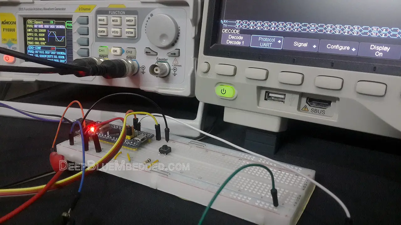
The Resulting UART Messages On Serial Port Terminal (Test Video)
My Comments On This LAB Results
The error (drift) in the frequency measurement is nearly 1% of the actual value. It’s not a constant flat rate, so we can compensate for it easily in code. And also the nature of the error suggests that it’s repeatable and can stem from a couple of reasons. First of all, the timer interrupt (every 50mSec) is an asynchronous signal. It arrives in no sync with the input signal, so a small drift in measurement is to be expected.
Another point is the interrupt latency can also contribute to a slight increase in the ticks count. And clearing both TIM2,3 at the end of ISR can help a little bit. We can actually eliminate this error percentage by some calibrations. However, there is and there will be a lot of limitations for this technique. The timer period (50mSec) defines the minimum allowed input signal that could be detected and measured.
So, as I’ve said earlier, it’s a good proof of concept and went successfully. But in the next tutorial, we’ll discuss the ICU (input capture unit) and how to set the timer module up so it can be used to detect external events in a very precise way. It’s the proper way to perform such measurement tasks and one of the most reliable options.
Stay tuned for the upcoming tutorials and don’t forget to SHARE these tutorials. And consider SUPPORTING this work to keep publishing free content just like this!
| Previous Tutorial | Tutorial 14 | Next Tutorial | |||||
