| Previous Tutorial | Tutorial 8 | Next Tutorial | |||||
| STM32 External Interrupt Pins & Interrupt Latency | |||||||
| STM32 Course Home Page ???? | |||||||
In this LAB, we’ll see how to set up a GPIO pin to be an interrupt pin on the rising, falling, or both edges. And we’ll write the ISR handler for this interrupt, in which we’ll toggle an output pin (e.g. LED). Finally, we’ll check the interrupt response time and interrupt latency.
[toc]
Required Components For LABs
All the example code/LABs/projects in the course are going to be done using those boards below.
- Nucleo32-L432KC (ARM Cortex-M4 @ 80MHz) or (eBay)
- Blue Pill STM32-F103 (ARM Cortex-M3 @ 72MHz) or (eBay)
- ST-Link v2 Debugger or (eBay)
| QTY | Component Name | ???? Amazon.com | ???? eBay.com |
| 2 | BreadBoard | Amazon | eBay |
| 1 | LEDs Kit | Amazon Amazon | eBay |
| 1 | Resistors Kit | Amazon Amazon | eBay |
| 1 | Capacitors Kit | Amazon Amazon | eBay & eBay |
| 2 | Jumper Wires Pack | Amazon Amazon | eBay & eBay |
| 1 | 9v Battery or DC Power Supply | Amazon Amazon Amazon | eBay |
| 1 | Micro USB Cable | Amazon | eBay |
| 1 | Push Buttons | Amazon Amazon | eBay |
★ Check The Full Course Complete Kit List
Some Extremely Useful Test Equipment For Troubleshooting:
- My Digital Storage Oscilloscope (DSO): Siglent SDS1104 (on Amazon.com) (on eBay)
- FeelTech DDS Function Generator: KKMoon FY6900 (on Amazon.com) (on eBay)
- Logic Analyzer (on Amazon.com) (on eBay)
Affiliate Disclosure: When you click on links in this section and make a purchase, this can result in this site earning a commission. Affiliate programs and affiliations include, but are not limited to, the eBay Partner Network (EPN) and Amazon.com.
LAB Objectives
| LAB Number | 3 |
| LAB Title | External Interrupt Pins |
- Configure GPIO Output Pin & Input Pin Within CubeMX Tool
- Configure the input pin to be an interrupt source on the rising edge
- Toggle the output pin when an interrupt is detected within the ISR handler
- Measure the interrupt response time between event and output change
STM32 CubeMX Configurations
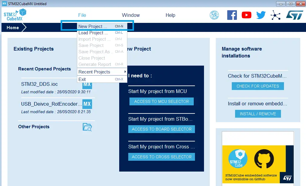
Step1: Open CubeMX & Create New Project
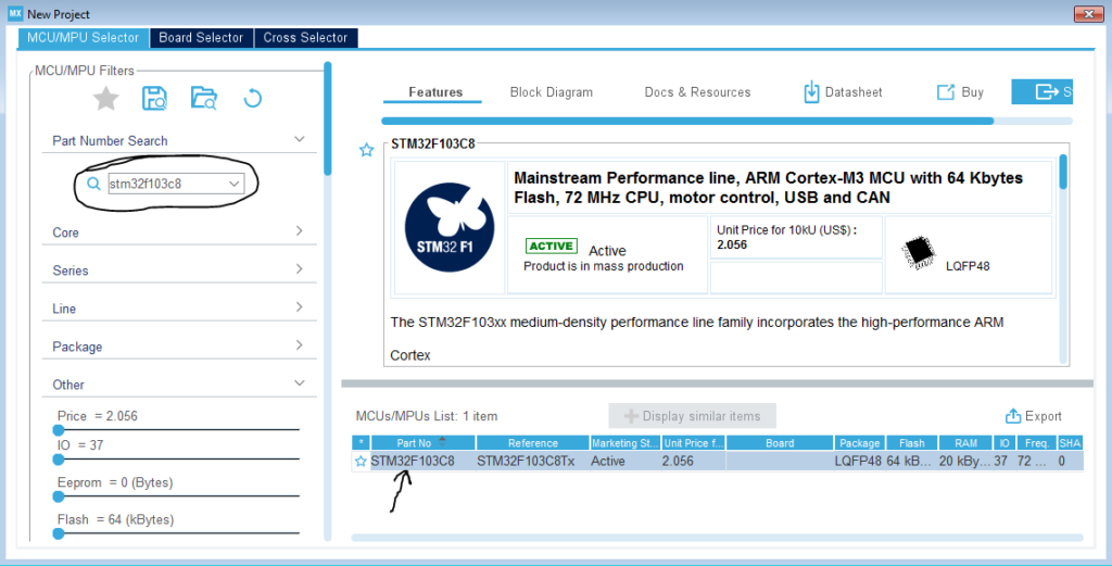
Step2: Choose The Target MCU & Double-Click Its Name
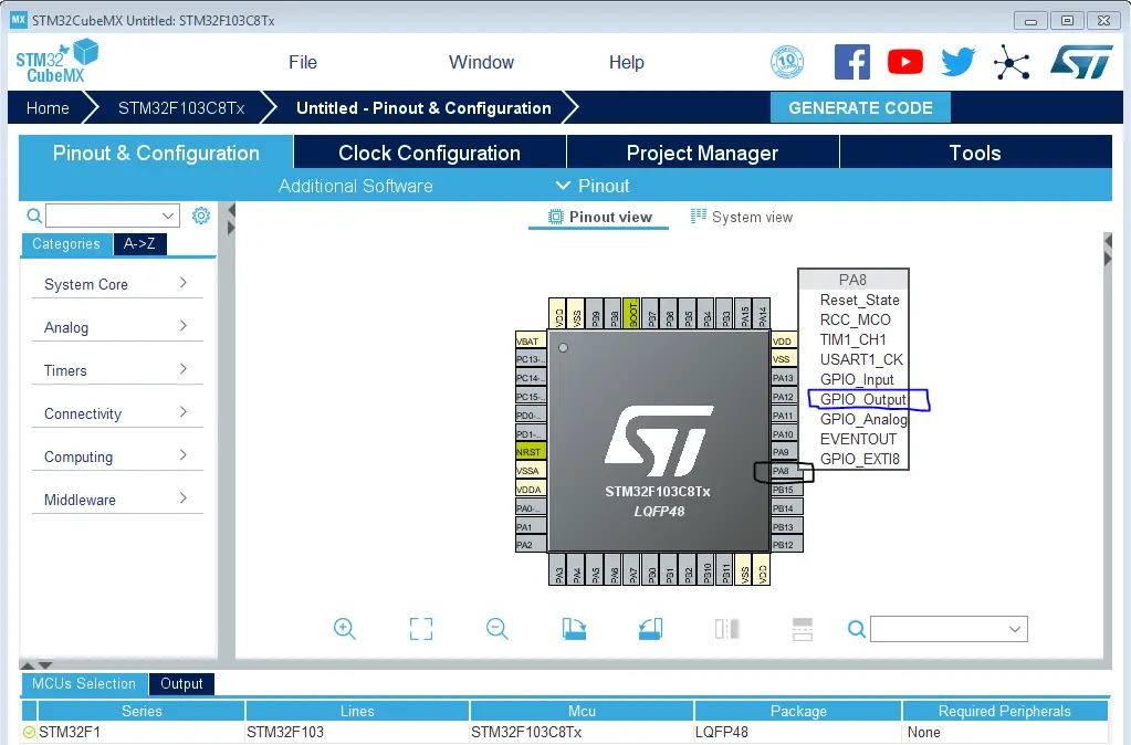
Step3: Click On The Pin You Want To Configure As An Output & Select Output Option
Let it be A8 pin for example! (The LED Pin)
Step4: Click On The Pin You Want To Configure As An External Interrupt Input
Let it be A9 pin for example! It’s EXTI line 9 (We’ll connect a push button to it).
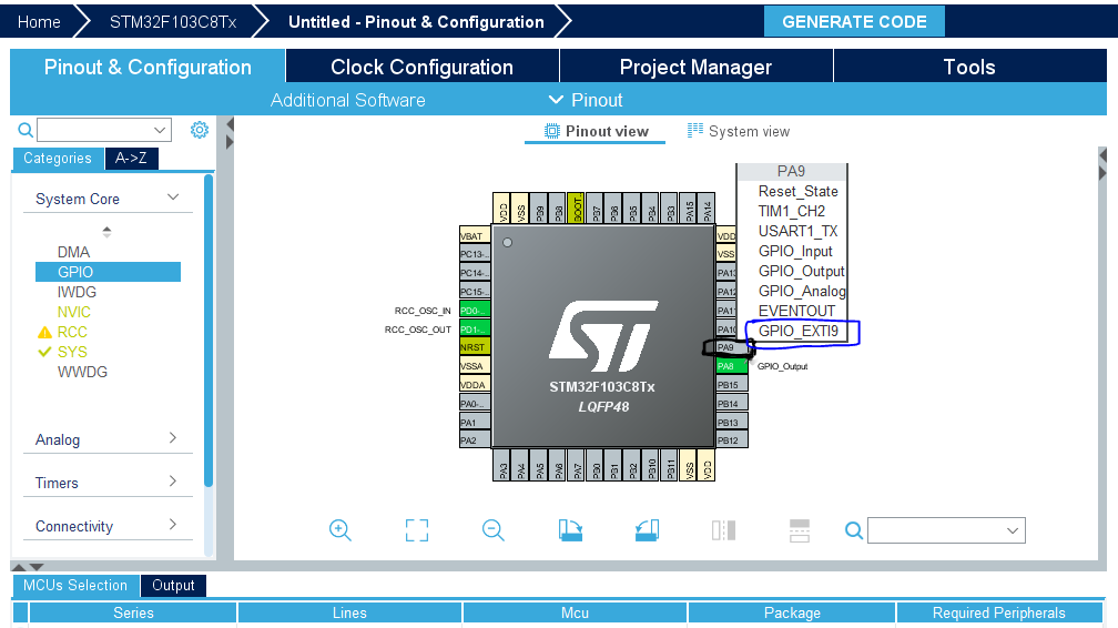
Step5: Go To GPIO Config Tab, And Select The A9 Pin EXTI interrupt edge and pull mode
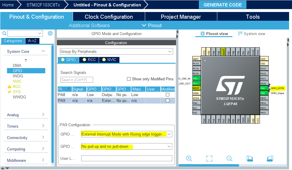
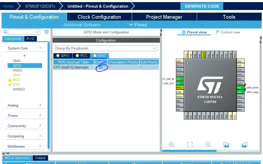
Step6: Open The NVIC Tab And Enable The EXTI line9 Interrupt
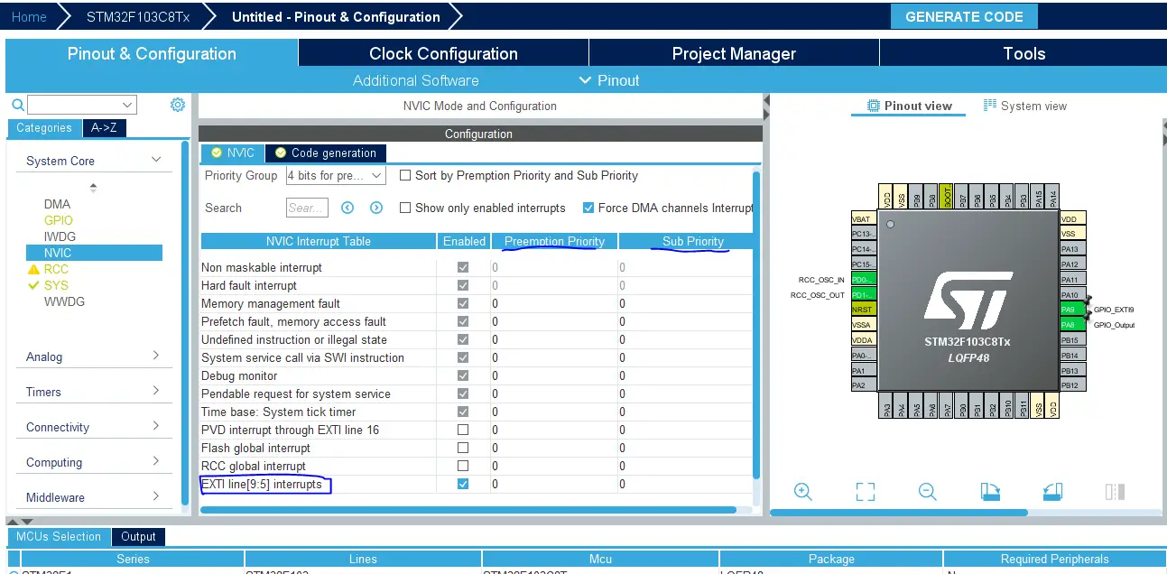
Step7: Open The NVIC Config Tab And Check if you want to change the priority of the EXTI line9 external interrupt or not (Optional Step)
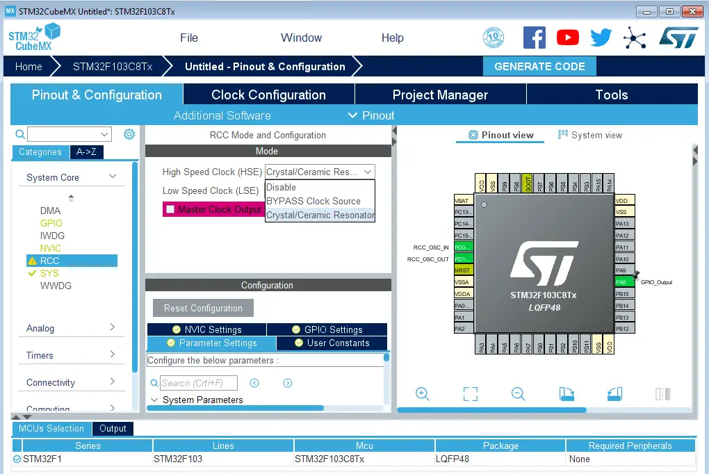
Step8: Set The RCC External Clock Source
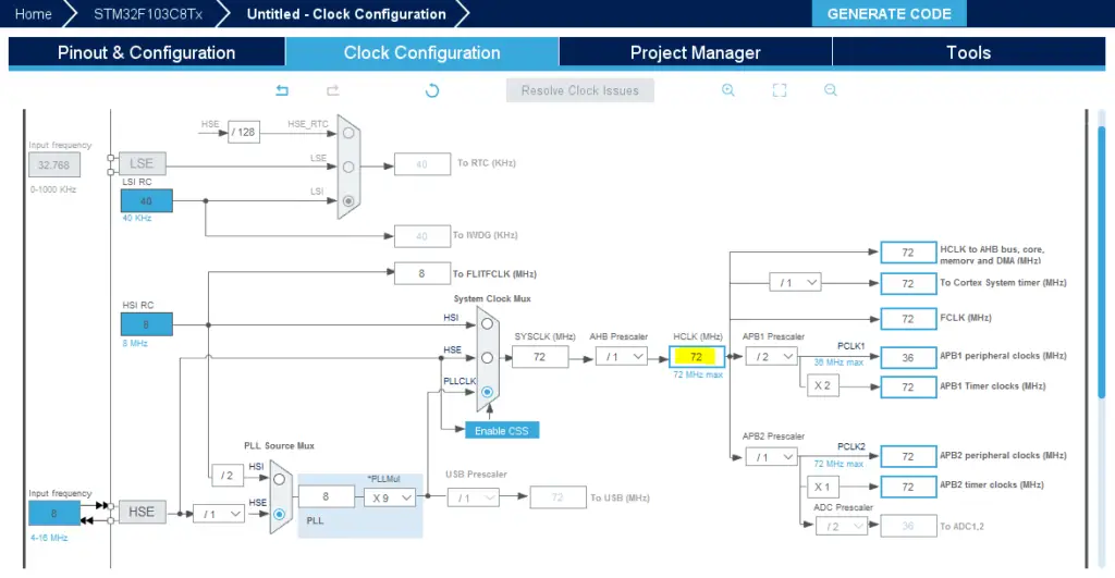
Step9: Go To The Clock Configuration
Step10: Set The System Clock To Be 72MHz Or Whatever You Want
Step11: Name & Generate The Project Initialization Code For CubeIDE or The IDE You’re Using
Then, open the project in the IDE you’re using. And head over to the main.c file. So we can start writing the application code and have a look at the initialization code generated by the STM32 CubeMX tool.
The Application Code In CubeIDE
Here is the generated initialization code in the main.c file
|
1 2 3 4 5 6 7 8 9 10 11 12 13 14 15 16 17 18 |
#include "main.h" void SystemClock_Config(void); static void MX_GPIO_Init(void); int main(void) { HAL_Init(); SystemClock_Config(); MX_GPIO_Init(); while (1) { } } |
Let’s have a look at the MX_GPIO_Init() function, as I wanna point to something in it.
|
1 2 3 4 5 6 7 8 9 10 11 12 13 14 15 16 17 18 19 20 21 22 23 24 25 26 27 28 29 |
static void MX_GPIO_Init(void) { GPIO_InitTypeDef GPIO_InitStruct = {0}; /* GPIO Ports Clock Enable */ __HAL_RCC_GPIOD_CLK_ENABLE(); __HAL_RCC_GPIOA_CLK_ENABLE(); /*Configure GPIO pin Output Level */ HAL_GPIO_WritePin(GPIOA, GPIO_PIN_8, GPIO_PIN_RESET); /*Configure GPIO pin : PA8 */ GPIO_InitStruct.Pin = GPIO_PIN_8; GPIO_InitStruct.Mode = GPIO_MODE_OUTPUT_PP; GPIO_InitStruct.Pull = GPIO_NOPULL; GPIO_InitStruct.Speed = GPIO_SPEED_FREQ_LOW; HAL_GPIO_Init(GPIOA, &GPIO_InitStruct); /*Configure GPIO pin : PA9 */ GPIO_InitStruct.Pin = GPIO_PIN_9; GPIO_InitStruct.Mode = GPIO_MODE_IT_RISING; GPIO_InitStruct.Pull = GPIO_NOPULL; HAL_GPIO_Init(GPIOA, &GPIO_InitStruct); /* EXTI interrupt init*/ HAL_NVIC_SetPriority(EXTI9_5_IRQn, 0, 0); HAL_NVIC_EnableIRQ(EXTI9_5_IRQn); } |
The last couple of lines in this function do the following: configure the EXTI line9 interrupt priority level, and enable its interrupt signal. The mode of the interrupt trigger is selected in the configuration of the input pin itself (on rising edge). And you can change it of course as per the application you’re currently developing.
The ISR that gets called and executed when this interrupt occurs can be found in the stm32f1xx_it.h file, so let’s head over to it now!
|
1 2 3 4 5 6 7 8 9 10 11 12 13 14 15 16 17 18 19 20 21 22 23 24 25 26 27 28 |
/******************************************************************************/ /* Cortex-M3 Processor Interruption and Exception Handlers */ /******************************************************************************/ void NMI_Handler(void) { /* USER CODE BEGIN NonMaskableInt_IRQn 0 */ /* USER CODE END NonMaskableInt_IRQn 0 */ /* USER CODE BEGIN NonMaskableInt_IRQn 1 */ /* USER CODE END NonMaskableInt_IRQn 1 */ } // And all other internal exceptions/interrupts handlers // .. // .. // .. /******************************************************************************/ /* STM32F1xx Peripheral Interrupt Handlers */ /* Add here the Interrupt Handlers for the used peripherals. */ /* For the available peripheral interrupt handler names, */ /* please refer to the startup file (startup_stm32f1xx.s). */ /******************************************************************************/ void EXTI9_5_IRQHandler(void) // <----- The ISR Function We're Looking For! { HAL_GPIO_EXTI_IRQHandler(GPIO_PIN_9); } |
Point the mouse to the function HAL_GPIO_EXTI_IRQHandler() and right-click its name and then open the declaration for it. This will take you to the source file where it’s defined, which is this file stm32f1xx_hal_gpio.c
Here is the function implementation you’ll see in this file.
|
1 2 3 4 5 6 7 8 9 |
void HAL_GPIO_EXTI_IRQHandler(uint16_t GPIO_Pin) { /* EXTI line interrupt detected */ if (__HAL_GPIO_EXTI_GET_IT(GPIO_Pin) != 0x00u) { __HAL_GPIO_EXTI_CLEAR_IT(GPIO_Pin); // Clears The Interrupt Flag HAL_GPIO_EXTI_Callback(GPIO_Pin); // Calls The ISR Handler CallBack Function } } |
This function clears the interrupt source, then calls the ISR handler callback function. So now, we’ll write our implementation for this callback function in our application (main.c file)
We’ll check the interrupt pin source, then toggle the output GPIO pin in this ISR handler callback. And that’s it for this LAB!
Full LAB Code (main.c)
|
1 2 3 4 5 6 7 8 9 10 11 12 13 14 15 16 17 18 19 20 21 22 |
int main(void) { HAL_Init(); SystemClock_Config(); MX_GPIO_Init(); while (1) { // Stay IDLE .. Everything is done in the ISR Handler } } // EXTI Line9 External Interrupt ISR Handler CallBackFun void HAL_GPIO_EXTI_Callback(uint16_t GPIO_Pin) { if(GPIO_Pin == GPIO_PIN_9) // If The INT Source Is EXTI Line9 (A9 Pin) { HAL_GPIO_TogglePin(GPIOA, GPIO_PIN_8); // Toggle The Output (LED) Pin } } |
Prototyping & Testing
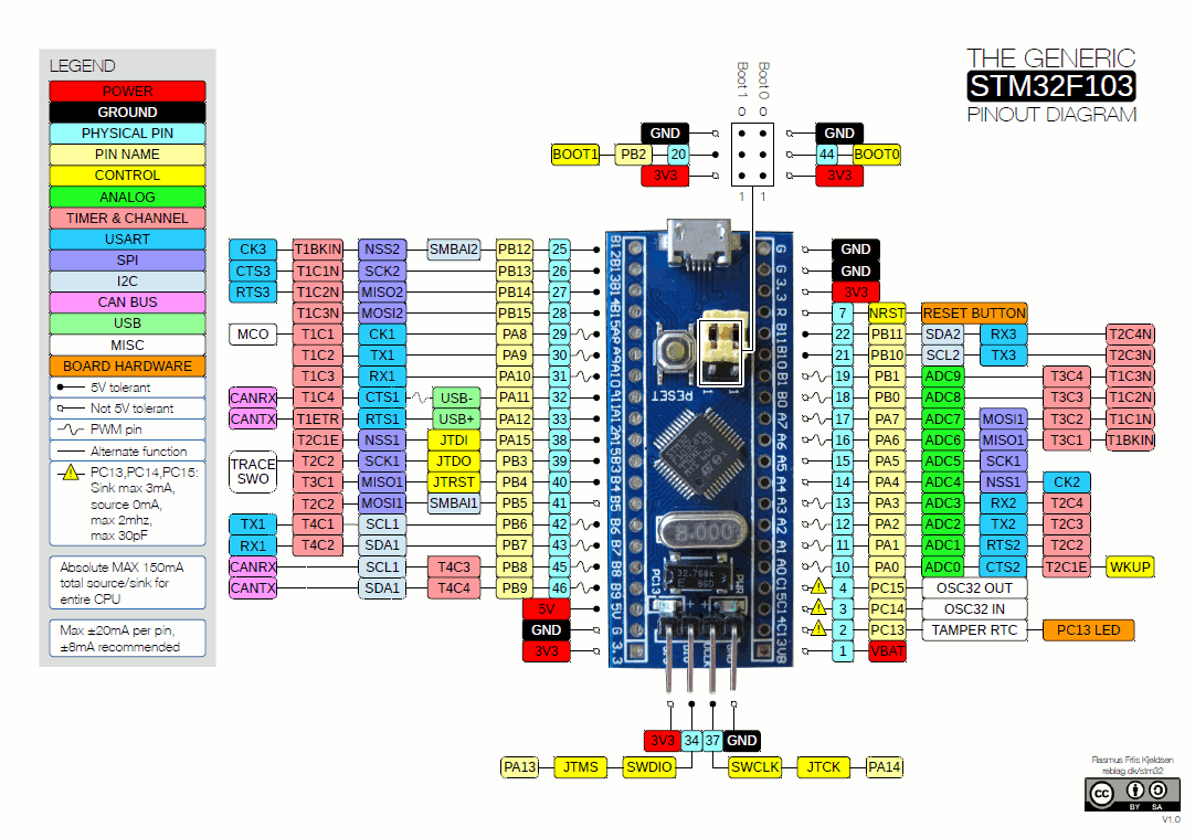
Step0: Refer To The Blue Pill Board Schematic & Pinout
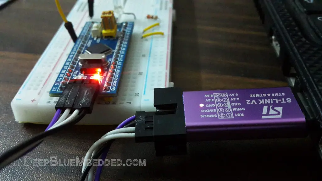
Step1: Connect The ST-Link To The USB Port & SWD Pins On Board
Step2: Click The Debug Button To Compile The Code & Flash It To The Board & Start A Debugging Session
Step3: You Can Stop The Debugging Session Or Keep It Going. But You Need To Restart The MCU Once To Run The New Application At The Booting Process.
Download External Interrupt LAB3 Project
The Results For This LAB
Test Video
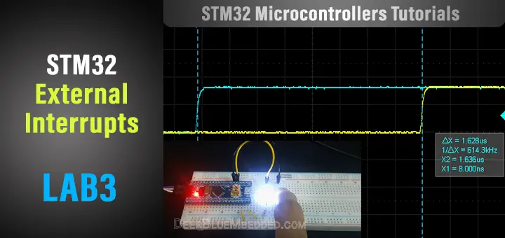
Interrupt Response Time Measurement On My DSO
- Blue Trace is the push button input signal
- Yellow Trace is the LED output pin
They are identical in the normal view as you can see. You can’t see any delay, the response looks immediate and the traces are overlapping.
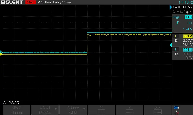
However, after zooming in time division, we can see a little bit of delay between the input button Rise to 1 and the LED state change. It’s measured to be nearly 1.6uSec.
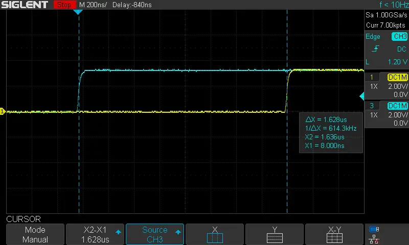
This includes the interrupt latency, context switching overhead, and ISR callback procedure as well as the HAL_TogglePin function call. All in all, it’s great response time. You can improve this by directly writing to the GPIO output pin port without using the HAL_GPIO function. This will be a topic for a future tutorial!
| Previous Tutorial | Tutorial 8 | Next Tutorial | |||||
