In this tutorial, we’ll discuss how the STM32 UART Half-Duplex (Single Wire) mode works. You’ll learn how to use the STM32 UART half-duplex mode to send and receive data over UART with a single wire.
We’ll implement an example project for STM32 UART Half-Duplex Transmitter/Receiver to practice what we’ll learn in this tutorial by creating two-way communication between two STM32 board over UART in half-duplex mode. Without further ado, let’s get right into it!
Table of Contents
- STM32 UART Half-Duplex (Single Wire) Mode
- How To Send Data With STM32 UART Half-Duplex
- How To Receive Data With STM32 UART Half-Duplex
- STM32 UART Half-Duplex Example Overview
- STM32 UART Half-Duplex (Single Wire) Example
- Wrap Up
STM32 UART Half-Duplex (Single Wire) Mode
The STM32 UART can be configured to operate in half-duplex mode (single wire). In this mode, the UART module can send or receive data using only one wire (line) but not at the same time. It keeps switching between transmitter mode and receiver mode in runtime to achieve this behavior.
In single-wire half-duplex mode, the TX and RX pins are connected internally. The RX pin is no longer used. The TX pin is always released when no data is transmitted. Thus, it acts as a standard IO in idle or in reception. This means that the IO must be configured so that TX pin is in alternate-function open-drain mode with an external pull-up resistor.
The STM32 UART hardware may or may not have this pull-up internally. This should be mentioned in the datasheet of the exact STM32 microcontroller. For the demo example I’ve created and tested on my hardware, it was necessary to hook up an external pull-up resistor to get it working reliably. A 4.7kΩ resistor to Vcc should be fine for most situations.
How To Send Data With STM32 UART Half-Duplex
To send data in half-duplex mode with STM32 UART, you need first to enable TX using the HAL_HalfDuplex_EnableTransmitter() function. Then, you can send the data you want to send over UART in half-duplex mode, and switch back to the RX (receiver) mode to capture any incoming data.
Here is an example code for how this is done using STM32 HAL APIs:
|
1 2 3 4 5 6 7 8 |
// Enable TX (Half-Duplex Mode) HAL_HalfDuplex_EnableTransmitter(&huart1); // Send The Data You Want! HAL_UART_Transmit(&huart1, UART1_TxBuffer, UART_TX_BUFFER_SIZE, 100); // Switch Back To RX (Receiver Mode) HAL_HalfDuplex_EnableReceiver(&huart1); |
How To Receive Data With STM32 UART Half-Duplex
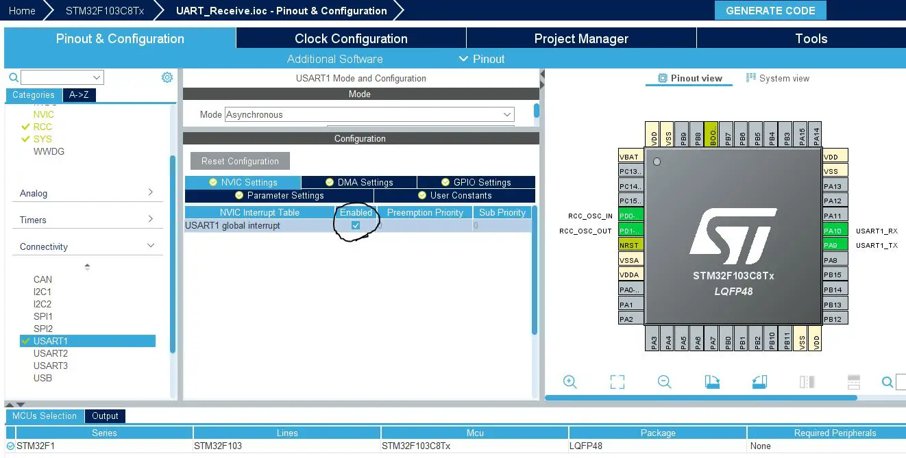
To receive data in half-duplex mode with STM32 UART, you need first to enable RX using the HAL_HalfDuplex_EnableReceiver() function. Then, you can receive data over UART in half-duplex mode. It’s better to use the IDLE Line Detection Receiving scheme to read any unknown number of incoming data bytes and make sure to have the UART interrupt enabled in the NVIC settings.
Here is an example code for how this is done using STM32 HAL APIs:
|
1 2 3 4 5 6 7 8 9 10 11 12 13 14 15 16 |
int main(void) { ... HAL_HalfDuplex_EnableReceiver(&huart1); HAL_UARTEx_ReceiveToIdle_IT(&huart1, UART1_RxBuffer, UART_RX_BUFFER_SIZE); ... } void HAL_UARTEx_RxEventCallback(UART_HandleTypeDef *huart, uint16_t Size) { RxDataLen = Size; // Process The Received Data & Update PWM Outputs ... // Re-Start The Receive Operation Again HAL_UARTEx_ReceiveToIdle_IT(&huart1, UART1_RxBuffer, UART_RX_BUFFER_SIZE); } |
STM32 UART Half-Duplex Example Overview
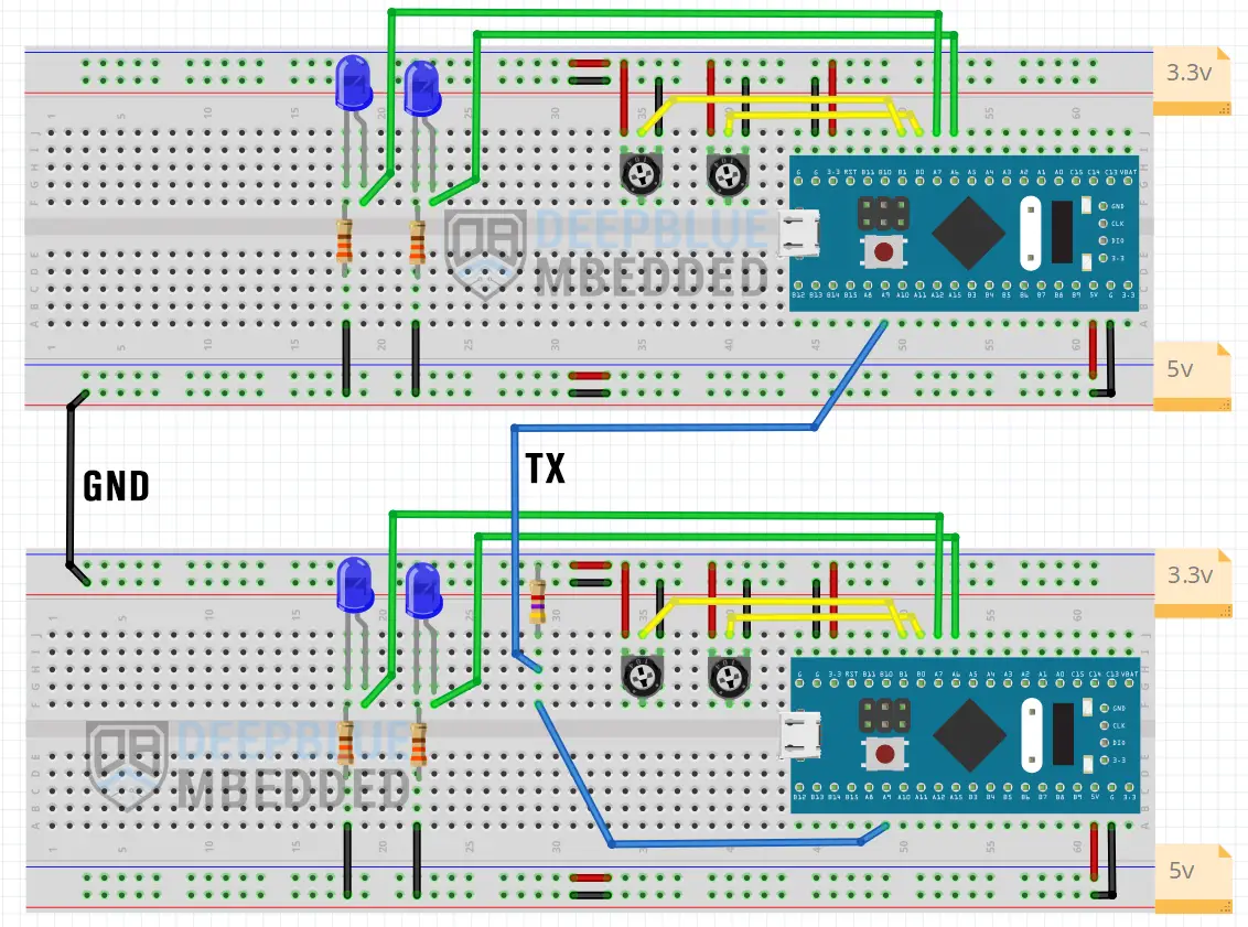
In the following example project, we’ll design a two-way communication system between two STM32 microcontrollers using the UART half-duplex single-wire mode.
In this system, each STM32 microcontroller will do the following functions:
- Read 2x potentiometers (12-Bit values scaled up to 16-bits)
- (every 5ms) Switch the UART to TX mode, send 4-Bytes of data containing the ADC readings of the 2 potentiometers, and switch back to RX mode
- When UART data is received with an IDLE line detection event, process the received 4-Bytes of data, and use it to control 2x output PWM LEDs
- Keep repeating
In other words, each one of the two STM32 microcontrollers will read its own two potentiometers and send the values to control the other STM32’s output LEDs brightness (PWM) over the half-duplex UART bus. Each microcontroller is sending and receiving data “apparently” at the same time in this system.
Here is the connection diagram for this example project.
STM32 UART Half-Duplex (Single Wire) Example
Step #1
Open STM32CubeMX, create a new project, and select the target microcontroller.
Step #2
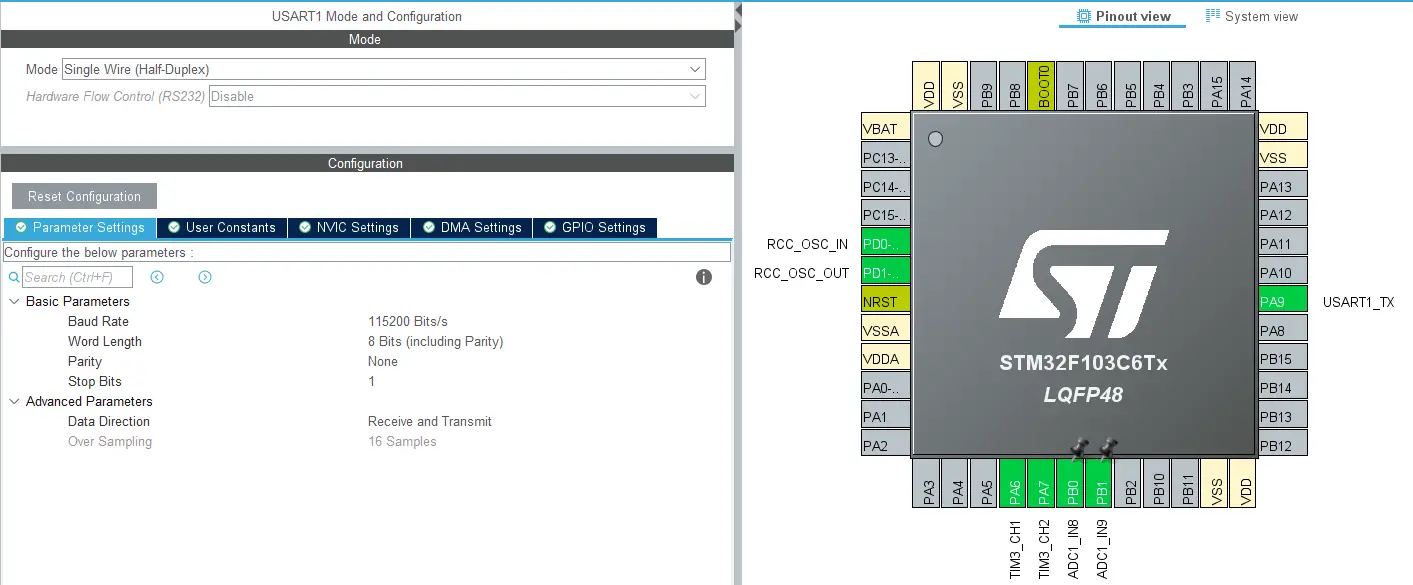
Enable UART1 in Single-Wire (Half-Duplex) mode and leave the default configurations as is.
Enable The USART1 Global Interrupt From The NVIC Settings Tab
Step #3
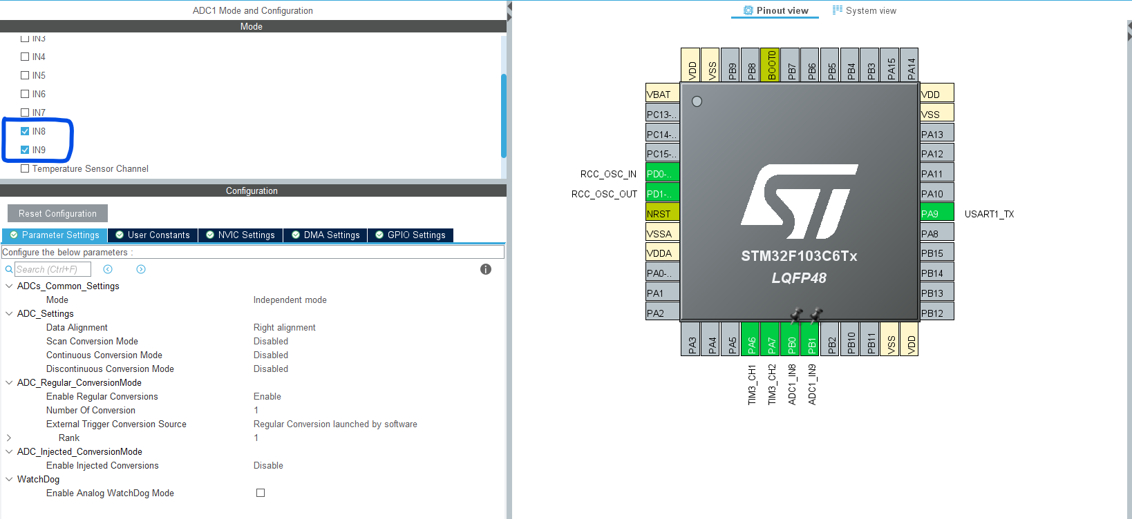
Enable the ADC channels: CH8 & CH9
Step #4
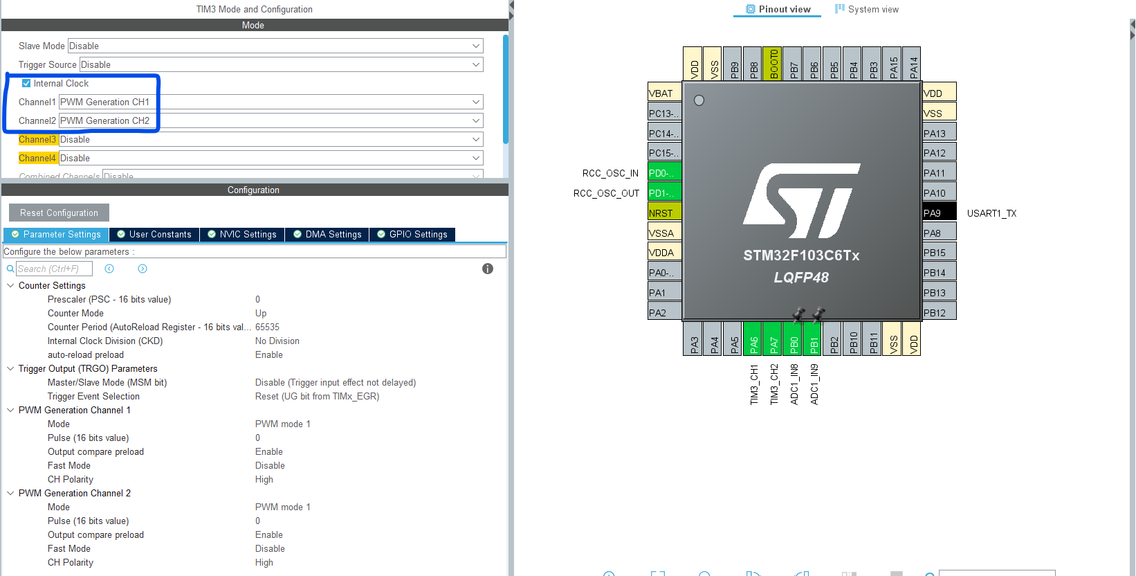
Configure Timer3 to generate 2x PWM outputs on CH1 & CH2 with default configurations as shown below.
Step #5
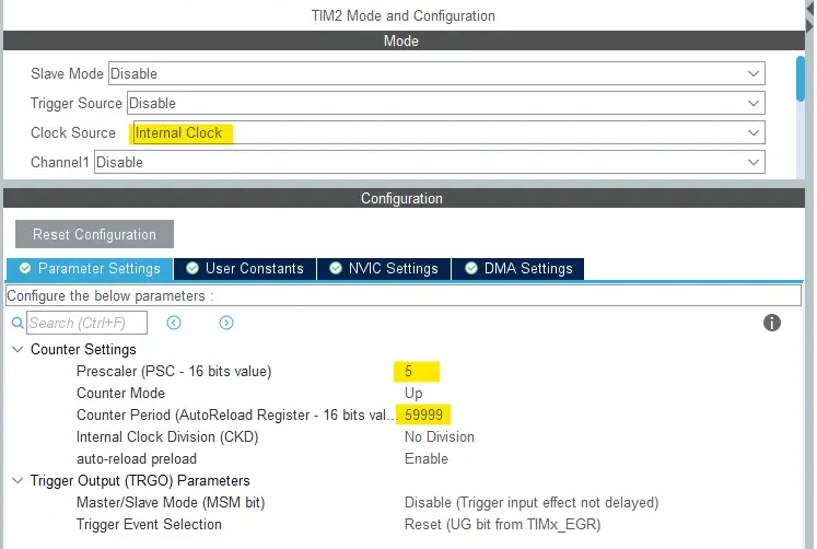
Configure Timer2 to generate an interrupt every 5ms using the configurations shown below. I’ve used this STM32 Timer Calculator to get these values.
Step #6
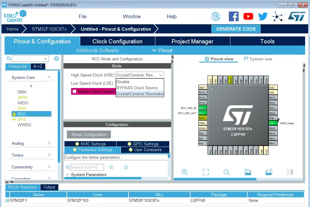
Go to the RCC clock configuration page and enable the HSE external crystal oscillator input.
Step #7
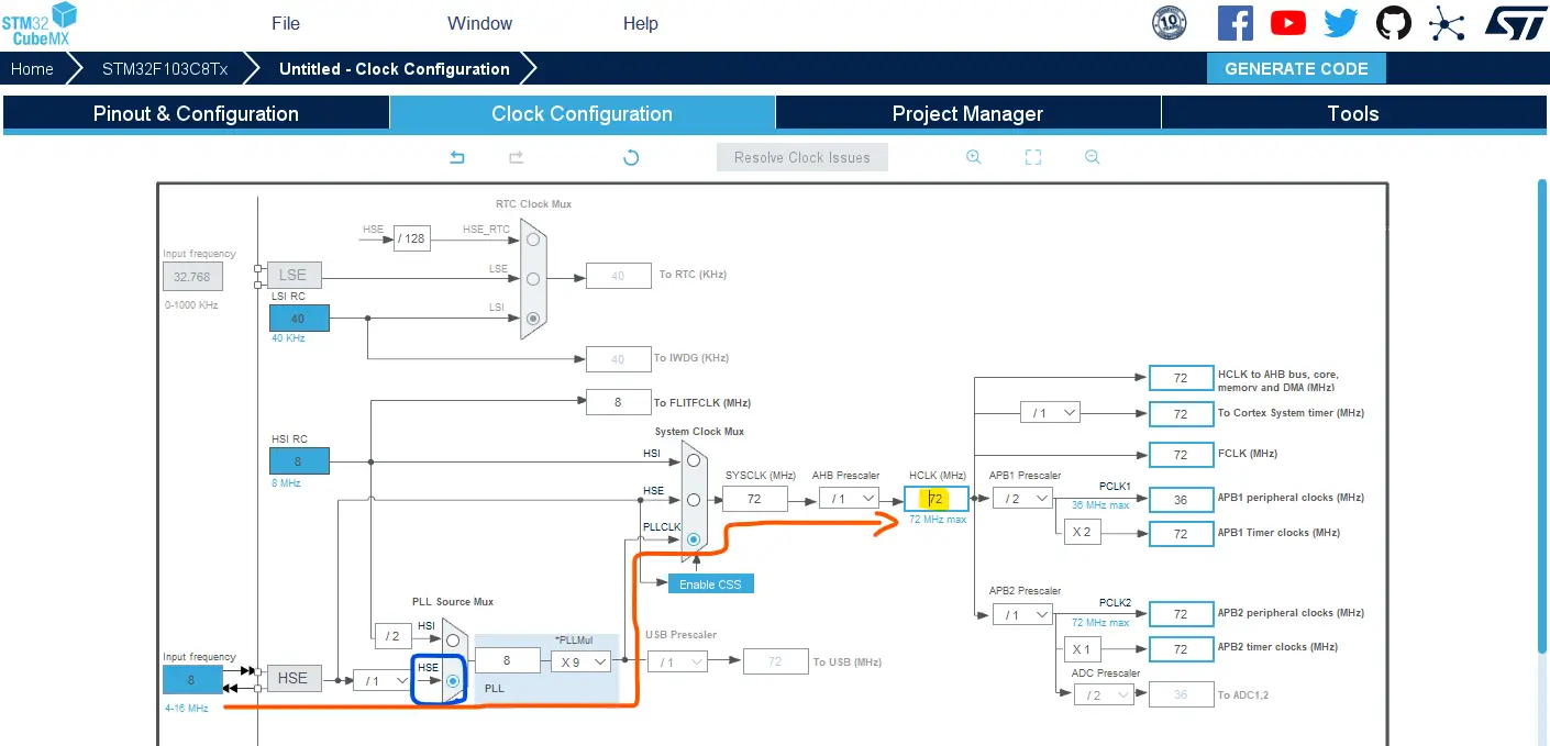
Go to the clock configurations page, and select the HSE as a clock source, PLL output, and type in 72MHz for the desired output system frequency. Hit the “ Enter” key, and let the application solve for the required PLL dividers/multipliers to achieve the desired clock rate.
Step #8
Name & Generate The Project Initialization Code For CubeIDE or The IDE You’re Using.
STM32 UART Half-Duplex Tx/Rx Example Code
Here is The Application Code For This LAB (main.c)
|
1 2 3 4 5 6 7 8 9 10 11 12 13 14 15 16 17 18 19 20 21 22 23 24 25 26 27 28 29 30 31 32 33 34 35 36 37 38 39 40 41 42 43 44 45 46 47 48 49 50 51 52 53 54 55 56 57 58 59 60 61 62 63 64 65 66 67 68 69 70 71 72 73 74 75 76 77 78 79 80 81 82 83 84 85 86 87 88 |
/* * LAB Name: STM32 UART Single-Wire (Half-Duplex) TxRx Example * Author: Khaled Magdy * For More Info Visit: www.DeepBlueMbedded.com */ #include "main.h" #define UART_RX_BUFFER_SIZE 40 #define UART_TX_BUFFER_SIZE 4 ADC_HandleTypeDef hadc1; TIM_HandleTypeDef htim2; TIM_HandleTypeDef htim3; UART_HandleTypeDef huart1; uint16_t i = 0, AD_RES[2]; ADC_ChannelConfTypeDef ADC_CH_Cfg = {0}; uint32_t ADC_Channels[2] = {ADC_CHANNEL_8, ADC_CHANNEL_9}; uint8_t UART1_RxBuffer[UART_RX_BUFFER_SIZE] = {0}; uint8_t UART1_TxBuffer[UART_TX_BUFFER_SIZE] = {0}; uint16_t RxDataLen = 0; void SystemClock_Config(void); static void MX_GPIO_Init(void); static void MX_ADC1_Init(void); static void MX_TIM2_Init(void); static void MX_TIM3_Init(void); static void MX_USART1_UART_Init(void); int main(void) { HAL_Init(); SystemClock_Config(); MX_GPIO_Init(); MX_ADC1_Init(); MX_TIM2_Init(); MX_TIM3_Init(); MX_USART1_UART_Init(); HAL_TIM_Base_Start_IT(&htim2); HAL_TIM_PWM_Start(&htim3, TIM_CHANNEL_1); HAL_TIM_PWM_Start(&htim3, TIM_CHANNEL_2); HAL_HalfDuplex_EnableReceiver(&huart1); HAL_UARTEx_ReceiveToIdle_IT(&huart1, UART1_RxBuffer, UART_RX_BUFFER_SIZE); ADC_CH_Cfg.Rank = ADC_REGULAR_RANK_1; ADC_CH_Cfg.SamplingTime = ADC_SAMPLETIME_1CYCLE_5; while (1) { for(i=0; i<2; i++) // Read The Potentiometers { ADC_CH_Cfg.Channel = ADC_Channels[i]; // Select The ADC Channel [i] HAL_ADC_ConfigChannel(&hadc1, &ADC_CH_Cfg); // Configure The Selected ADC Channel HAL_ADC_Start(&hadc1); // Start ADC Conversion @ Selected Channel HAL_ADC_PollForConversion(&hadc1, 1); // Poll The ADC Channel With TimeOut = 1mSec AD_RES[i] = (HAL_ADC_GetValue(&hadc1) << 4); // Read The ADC Conversion Result } HAL_Delay(1); } } void HAL_TIM_PeriodElapsedCallback(TIM_HandleTypeDef* htim) { if(htim->Instance == TIM2) { // Pack The ADC Results into UART1_TxBuffer & Send it Over UART UART1_TxBuffer[0] = (uint8_t)(AD_RES[0] & 0xFF); // Lower byte of AD_RES[0] UART1_TxBuffer[1] = (uint8_t)((AD_RES[0] >> 8) & 0xFF); // Upper byte of AD_RES[0] UART1_TxBuffer[2] = (uint8_t)(AD_RES[1] & 0xFF); // Lower byte of AD_RES[1] UART1_TxBuffer[3] = (uint8_t)((AD_RES[1] >> 8) & 0xFF); // Upper byte of AD_RES[1] HAL_HalfDuplex_EnableTransmitter(&huart1); HAL_UART_Transmit(&huart1, UART1_TxBuffer, UART_TX_BUFFER_SIZE, 1000); // Switch Back To Receiver Mode HAL_HalfDuplex_EnableReceiver(&huart1); } } void HAL_UARTEx_RxEventCallback(UART_HandleTypeDef *huart, uint16_t Size) { RxDataLen = Size; // Process The Received Data & Update PWM Outputs if(RxDataLen == UART_TX_BUFFER_SIZE) { TIM3->CCR1 = (uint16_t)UART1_RxBuffer[0] | ((uint16_t)UART1_RxBuffer[1] << 8); TIM3->CCR2 = (uint16_t)UART1_RxBuffer[2] | ((uint16_t)UART1_RxBuffer[3] << 8); } // Re-Start The Receive Operation Again HAL_UARTEx_ReceiveToIdle_IT(&huart1, UART1_RxBuffer, UART_RX_BUFFER_SIZE); } |
Code Explanation
In the main() function, we Call the HAL_UARTEx_ReceiveToIdle_IT() to start the reception of UART data in the UART1_RxBuffer using IDLE line detection in interrupt mode.
In the while(1) super loop, we keep sampling the 2x ADC channels to get the potentiometers readings using This ADC Multi-Channel Sampling Technique and store the results in this AD_RES[] buffer array.
Every 5ms, a Timer2 interrupt is fired and the CPU starts executing the HAL_TIM_PeriodElapsedCallback() ISR handler function. In which it does the following:
- Pack the ADC readings into the UART1_TxBuffer array.
- Switch the UART mode from receiver to transmitter
- Transmit the UART1_TxBuffer data
- Switch back to UART receiver mode
The Rx interrupt is fired and the ISR function HAL_UARTEx_RxEventCallback() is called whenever the hardware detects an IDLE event or we’ve already received the maximum buffer length of data UART_RX_BUFFER_SIZE. In the ISR Callback function:
- Save the received data length (size) into the RxDataLen variable
- Process the received data (ADC readings) and reconstruct the original value of each reading
- Update the PWM output duty cycle according to the received ADC readings
- Re-start the UART data reception with IDLE line detection in interrupt mode again, and so on…
STM32 UART Single Wire Tx/Rx Example Testing
This is the testing result for this example project on my two STM32 blue pill boards (F103C6T6). Note how each board’s potentiometers control the other’s LEDs brightness which verifies that the two-way communication is properly established.
Required Parts For STM32 Examples
All the example Code/LABs/Projects in this STM32 Series of Tutorials are done using the Dev boards & Electronic Parts Below:
| QTY. | Component Name | Amazon.com | AliExpress | eBay |
| 1 | STM32-F103 BluePill Board (ARM Cortex-M3 @ 72MHz) | Amazon | AliExpress | eBay |
| 1 | Nucleo-L432KC (ARM Cortex-M4 @ 80MHz) | Amazon | AliExpress | eBay |
| 1 | ST-Link V2 Debugger | Amazon | AliExpress | eBay |
| 2 | BreadBoard | Amazon | AliExpress | eBay |
| 1 | LEDs Kit | Amazon & Amazon | AliExpress | eBay |
| 1 | Resistors Kit | Amazon & Amazon | AliExpress | eBay |
| 1 | Capacitors Kit | Amazon & Amazon | AliExpress & AliExpress | eBay & eBay |
| 1 | Jumper Wires Pack | Amazon & Amazon | AliExpress & AliExpress | eBay & eBay |
| 1 | Push Buttons | Amazon & Amazon | AliExpress | eBay |
| 1 | Potentiometers | Amazon | AliExpress | eBay |
| 1 | Micro USB Cable | Amazon | AliExpress | eBay |
★ Check The Links Below For The Full Course Kit List & LAB Test Equipment Required For Debugging ★
Download Attachments
You can download all attachment files for this Article/Tutorial (project files, schematics, code, etc..) using the link below. Please consider supporting our work through the various support options listed in the link down below. Every small donation helps to keep this website up and running and ultimately supports the whole community.
Wrap Up
In conclusion, we’ve explored how to set up the STM32 UART in Half-Duplex mode to transmit and receive data on the same line (wire) and we’ve established a 2-way communication between 2 STM32 boards using UART half-duplex mode. You can build on top of the example provided in this tutorial and/or explore the other parts of this STM32 UART tutorial series linked below.
