This is a comprehensive guide for STM32 I2C LCD Interfacing (I2C LCD 16×2, 20×4, and Multiple I2C LCDs). You’ll learn how to use our STM32 I2C LCD Library and create some example projects to practice what we’ll be learning in this tutorial. We’ll implement the following examples in this tutorial:
- STM32 I2C LCD 16×2 Text Display
- STM32 I2C LCD 16×2 Scrolling Text Display
- STM32 I2C LCD 16×2 Custom Characters Display
- Multiple I2C LCD Displays Interfacing With STM32
- STM32 I2C LCD 20×4 Display Interfacing
We’ll start off by explaining how the I2C LCD module works, its pinout, and how to connect it to your STM32 board. We’ll display some text on the I2C LCD screen, make the text scroll on the LCD, and also create some custom characters and emojis. Without further ado, let’s get right into it!
Table of Contents
- STM32 I2C LCD
- STM32 I2C LCD Interfacing
- STM32 I2C LCD Library (Driver)
- STM32 I2C LCD Library Integration
- STM32 I2C LCD 16×2 Example
- STM32 I2C LCD 16×2 Example Code [Project]
- STM32 Multiple I2C LCD Example Code [Project]
- STM32 I2C LCD Common Issues Troubleshooting
- Wrap Up
STM32 I2C LCD
LCD (Liquid Crystal Display) is typically used in embedded systems to display text and numbers for the end user as an output device. The 16×2 alphanumeric display is based on the Hitachi HD44780 driver IC. Which is the small black circular chip on the back of the LCD module itself. This is the controller that controls the LCD unit and we communicate with using an STM32 microcontroller to send commands and text messages.
Alphanumeric LCD 16×2
The LCD module consists of 16×2 character cells (2 rows x 16 columns), each cell of which is 5×8 dots. Controlling all of these individual dots is a tedious task for our STM32 microcontroller. However, it doesn’t have to do so. As there is a specific function controller on the LCD itself controlling the display while reading the user’s commands & data (the Hitachi HD44780 controller).

The tutorial linked below is highly recommended to learn more about STM32 LCD interfacing with GPIO-based Library, it’s bare metal and very informative.
")
This article will provide you with more in-depth information about STM32 LCD 16×2 interfacing, how LCDs work, how to use the GPIO-based LCD16X2 library and integrate it into your projects, and more. It’s highly recommended!
I2C LCD Module (PCF8574 IO Expander)
The I2C IO expander IC (PCF8574) is commonly used as a cheap solution to implement an I2C LCD interface that replaces the classic parallel connection to the LCDs (at least 6 pins) with an easy-to-use I2C bus (only 2 pins). Using it saves a lot of the STM32 microcontroller’s IO pins that would have been consumed to create a generic LCD parallel communication.

Moreover, it’s shared with all I2C devices on the bus, so you can still have so many other modules/sensors connected on the same bus. In this previous article, We’ve demonstrated everything about this IC using its datasheet and build a driver library (in Embedded-C) for this IC. You can check it out if you’re interested in learning more about it.

In this tutorial, we’ll only discuss the important things that you need to know in order to get started with I2C LCD interfacing with STM32.
I2C LCD Address (Default)
You need to refer to the PCF8574 chip manufacturer’s datasheet to make sure what’s the I2C device address for the chip you’ve got around. If you’ve got an I2C LCD with Ti (Texas Instruments) PCF8574 chip, the default I2C address is 0x27 which is the 7-Bit device address with the three least significant bits (A0 – A1 – A2) are pulled up to HIGH.
If you’ve got an I2C LCD with an NXP PCF8574 chip, the default I2C address is therefore 0x3F. The question is what if we’d like to add multiple I2C LCDs to the I2C bus and control them with an STM32 microcontroller, how is that possible?
First of all, any I2C device on the bus must have a unique address. Therefore, we need to change the I2C address of the PCF8574 module if we’d like to add multiple units of it on the same I2C bus. Let’s next see how to do it!
Change I2C LCD Address
The I2C LCD interface (PCF8574) has 3 solder pads on the module’s board which control the value of the last 3 digits in the 7-Bit address of the device (A0 – A1 – A2). The pins are by default (internally) pulled up to HIGH (1), but if we short the solder pads together, this will drive the corresponding address bit pin to LOW (0). And that’s how we can change the device address.

You can use the interactive tool below to check the I2C LCD device address after soldering any of the solder pads (A0, A1, or A2). There are 8 different combinations, which means we can connect up to 8 different I2C LCDs on the same bus with a single STM32 board and control all of them at the same time.
I2C LCD Address (Texas Instruments’ PCF8574)
I2C LCD Address (NXP’s PCF8574)
The I2C LCD module has a default I2C device address of either 0x27 or 0x3F depending on the hardware manufacturer. If you’re not quite sure about the device address, you can use this STM32 I2C Scanner application to detect the exact device address.
Using the solder pads on the PCD8574 module will enable you to set the low 3 address bits (A0-A1-A2). This means we can have up to 8 different address combinations and consequently be able to connect up to 8 I2C LCD units on the same I2C bus and control them with only one STM32 microcontroller.
STM32 I2C LCD Interfacing
Now, let’s move to interfacing the I2C LCD 16×2 display with STM32. Let’s check the pinout, wiring diagram, LCD contrast control, and the I2C LCD device address.
I2C LCD Pinout
The I2C LCD Display has only four pins. The pinout is shown below:

GND is the ground pin.
Vcc is the LCD’s power supply input pin (connects to +5v).
SDA is the serial data line for the I2C LCD interface.
SCL is the serial clock line for the I2C LCD interface.
Wiring I2C LCD With STM32 Blue Pill
Here is the wiring diagram for the I2C LCD display with STM32 Blue Pill board that we’ll be using in the examples hereafter in this tutorial.

Contrast Adjustment For I2C LCD
After connecting the I2C LCD module, you’ll be able to control the LCD contrast by using the PCF8574 module’s on-board potentiometer. Turn it to the right and to the left until you feel satisfied with the current contrast level.
Get The I2C LCD Address
If you’re not quite sure about the I2C LCD’s device address, you can use the code example below and run it on your STM32 board after connecting the I2C LCD display to your board. It’ll automatically detect and print out the I2C device address for the LCD over the serial monitor.
/*
 * File: I2C_Scanner
 * Author:     Khaled Magdy
 * -------------------------------------------
 * For More Information, Tutorials, etc.
 * Visit Website: www.DeepBlueMbedded.com
 *
 */
#include "main.h"
#include "stdio.h"

I2C_HandleTypeDef hi2c1;
UART_HandleTypeDef huart1;

uint8_t Buffer[25] = {0};
uint8_t Space[] = " - ";
uint8_t StartMSG[] = "Starting I2C Scanning: \r\n";
uint8_t EndMSG[] = "Done! \r\n\r\n";

void SystemClock_Config(void);
static void MX_GPIO_Init(void);
static void MX_I2C1_Init(void);
static void MX_USART1_UART_Init(void);

int main(void)
{
    uint8_t i = 0, ret;

    HAL_Init();
    SystemClock_Config();
    MX_GPIO_Init();
    MX_I2C1_Init();
    MX_USART1_UART_Init();

    HAL_Delay(1000);

    /*-[ I2C Bus Scanning ]-*/
    HAL_UART_Transmit(&huart1, StartMSG, sizeof(StartMSG), 10000);
    for(i=1; i<128; i++)
    {
        ret = HAL_I2C_IsDeviceReady(&hi2c1, (uint16_t)(i<<1), 3, 5);
        if (ret != HAL_OK) /* No ACK Received At That Address */
        {
            HAL_UART_Transmit(&huart1, Space, sizeof(Space), 10000);
        }
        else if(ret == HAL_OK)
        {
            sprintf(Buffer, "0x%X", i);
            HAL_UART_Transmit(&huart1, Buffer, sizeof(Buffer), 10000);
        }
    }
    HAL_UART_Transmit(&huart1, EndMSG, sizeof(EndMSG), 10000);
    /*--[ Scanning Done ]--*/
    while (1)
    {
    }
}
For more information about how to use this I2C scanner script, check its full tutorial linked below.

This article will give you more in-depth information about the STM32 I2C Scanner application and how to use it to detect various I2C devices’ addresses.
STM32 I2C LCD Library (Driver)
Let’s now move on to the STM32 I2C LCD library that I’ve developed for this STM32 series of tutorials which is probably what we’ve searched for before landing on this article. In this section, we’ll explore the library files, functions, and configurations. So you can make the best use of it and also know how to modify or add any extra functionalities that your project needs.
In the next section, we’ll discuss how to integrate this STM32 I2C LCD library into your STM32 CubeIDE projects step-by-step.
STM32 I2C_LCD Library Directory & Files
The STM32 I2C_LCD library is part of the ECUAL (ECU abstraction layer) that we’re continuously building through this STM32 Series of Tutorials. The driver consists of 4 files: 2 core files (a header file & a source file) + 2 configuration files (a header & a source).
- I2C_LCD.h
- I2C_LCD.c
- I2C_LCD_cfg.h
- I2C_LCD_cfg.c

The STM32 I2C_LCD library needs you to also include the util library as a dependency because it uses the delay utility built into the util driver. The util library is also provided in the download section & code examples near the end of this tutorial.
STM32 I2C LCD Library APIs (Functions)
The core header file ( I2C_LCD.h) has all functions’ declarations (APIs) that we’ll be using in our application layer.
I2C_LCD.h File
#define I2C_LCD_MAX	1	// Maximum Number of I2C_LCD Modules in Your Project
#define I2C_LCD_1	0	// I2C_LCD Instance Number 1 (Add more if you need)

//-----[ Prototypes For All User External Functions ]-----

void I2C_LCD_Init(uint8_t I2C_LCD_InstanceIndex);
void I2C_LCD_Clear(uint8_t I2C_LCD_InstanceIndex);
void I2C_LCD_Home(uint8_t I2C_LCD_InstanceIndex);
void I2C_LCD_SetCursor(uint8_t I2C_LCD_InstanceIndex, uint8_t Col, uint8_t Row);
void I2C_LCD_WriteChar(uint8_t I2C_LCD_InstanceIndex, char Ch);
void I2C_LCD_WriteString(uint8_t I2C_LCD_InstanceIndex, char* Str);

void I2C_LCD_ShiftLeft(uint8_t I2C_LCD_InstanceIndex);
void I2C_LCD_ShiftRight(uint8_t I2C_LCD_InstanceIndex);

void I2C_LCD_Backlight(uint8_t I2C_LCD_InstanceIndex);
void I2C_LCD_NoBacklight(uint8_t I2C_LCD_InstanceIndex);
void I2C_LCD_Display(uint8_t I2C_LCD_InstanceIndex);
void I2C_LCD_NoDisplay(uint8_t I2C_LCD_InstanceIndex);
void I2C_LCD_Cursor(uint8_t I2C_LCD_InstanceIndex);
void I2C_LCD_NoCursor(uint8_t I2C_LCD_InstanceIndex);
void I2C_LCD_Blink(uint8_t I2C_LCD_InstanceIndex);
void I2C_LCD_NoBlink(uint8_t I2C_LCD_InstanceIndex);

void I2C_LCD_CreateCustomChar(uint8_t I2C_LCD_InstanceIndex, uint8_t CharIndex, const uint8_t* CharMap);
void I2C_LCD_PrintCustomChar(uint8_t I2C_LCD_InstanceIndex, uint8_t CharIndex);
I2C_LCD.c File
// Too long to paste here, but it has the definition of all API functions declared in the header file
// + any internal supplementary static functions
Note that all of the library interface functions have the first input argument as uint8_t which is inteded to be the index of the I2C_LCD instance you’re addressing. This library supports multiple instances of creation and individual addressing for multiple I2C_LCD display units. We’ll create an example for this multi-LCD application later on in this tutorial.
STM32 I2C LCD Library Configurations
The STM32 I2C_LCD library can be easily configured using the configuration files ending with (_cfg), and here is how it works. The configuration header file declares a struct that packs up all the configuration parameters into one variable type as shown below.
I2C_LCD_cfg.h File
typedef struct
{
	// I2C LCD Module Instance Index
	uint8_t I2C_LCD_Instance;

	// I2C Hardware Peripheral Handle
	I2C_HandleTypeDef* I2C_Handle;

	// I2C LCD Hardware Device Address
	uint8_t I2C_LCD_Address;

	// I2C LCD Columns Count
	uint8_t I2C_LCD_nCol;

	// I2C LCD Rows Count
	uint8_t I2C_LCD_nRow;

}I2C_LCD_CfgType;

extern const I2C_LCD_CfgType I2C_LCD_CfgParam[I2C_LCD_MAX];
The configuration parameter type declared above will allow the user to choose the following: (LCD instance index, I2C module’s handle pointer variable, the I2C device address, the LCD’s columns count, and the LCD’s rows count).
The configuration source file will have the actual configuration parameter variable creation and assignation. This is the file you need to edit in order to configure this STM32 I2C_LCD library. So you can assign the desired configuration parameters.
I2C_LCD_cfg.c File
extern I2C_HandleTypeDef hi2c1;

const I2C_LCD_CfgType I2C_LCD_CfgParam[I2C_LCD_MAX] =
{
	{   /*  Configuration Parameter For I2C_LCD Instance #1   */
		I2C_LCD_1,	/* Index of I2C_LCD Instance #1           */
		&hi2c1,		/* Hardware I2C Module's Handle           */
		0x27,		/* Hardware I2C_LCD Device Address        */
		16,			/* LCD Columns Count                      */
		2			/* LCD Rows Count                         */
	}
};
Note that the I2C module’s handle is externed in the I2C_LCD_cfg.c file to be used by the driver code internally. If you’re using any other I2C module (like I2C2, I2C3, or multiple of them) those should also be externed in this file as well. So that the configuration structure is able to access those handle variables.
Also note that the configuration parameter structure is externed to the header file so that in the I2C_LCD.c source code we can include the configuration header file I2C_LCD_cfg.h and see that global config parameter and use it internally.
Download The ECUAL/ I2C_LCD Driver Folder
STM32 I2C LCD Library Integration
In this section, we’ll discuss how to integrate the STM32 I2C_LCD library into your projects step-by-step. Assuming you’ve downloaded the provided library files from the links in this tutorial or from the GitHub Repo for this STM32 Tutorials Series, here is how you can use it in action.
The steps below apply to any other driver (library) in the ECUAL software components directory.
Step #1
Configure The Required Hardware Peripherals in STM32CubeMX
The first step is to head over to STM32CubeMX, create a new project, and configure the hardware needed for the library.
STM32 I2C_LCD Library HW Requirements
- 1x I2C Module (Default Configurations)

You can choose any I2C module you want.
Add any other peripherals you need in your project and configure the RCC clock however you want. There is no conflict between the I2C_LCD library and any other hardware configurations you may do in CubeMX.
Once you’re done with CubeMX configurations, generate the project code and head over to STM32CubeIDE.
Step #2
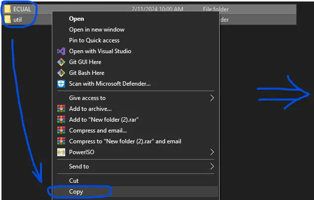
Copy & Paste The Library Folders
Copy the provided library folders (ECUAL/I2C_LCD + util) and open the STM32CubeIDE.
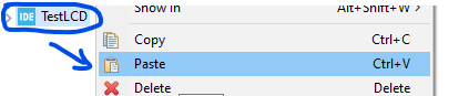
In STM32CubeIDE, right-click the project name and paste the library folders.
 |  | So it’ll look like this at the end: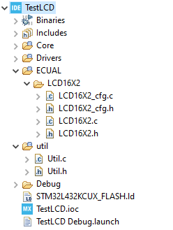 |
Step #3
Add The Library Directories To Paths & Symbols
The library folders have been added to our project but it’s not yet considered as a source code directory, so it won’t be compiled and give you a linking error in the linking stage if you call any of its functions.
Right-click the project name and click Properties. And navigate to C/C++ paths and symbols, and source locations tab. In the source locations tab, click add folder and add our library folders (ECUAL + util).

Step #4
Configure The I2C_LCD Library Using The cfg Parameter
Open the I2C_LCD_cfg.c file and modify the configuration parameter items to match your hardware setup (the I2C module’s handle, I2C device address, and the actual LCD size).
Step #5
Include The Library Header File & Use it!
Now you’re ready to use the STM32 I2C_LCD library, just include the header file as shown in the test code below.
/*
 * LAB Name: STM32 I2C LCD Example
 * Author: Khaled Magdy
 * For More Info Visit: www.DeepBlueMbedded.com
*/
#include "main.h"
#include "../../ECUAL/I2C_LCD/I2C_LCD.h"

#define MyI2C_LCD I2C_LCD_1

I2C_HandleTypeDef hi2c1;

void SystemClock_Config(void);
static void MX_GPIO_Init(void);
static void MX_I2C1_Init(void);

int main(void)
{
  HAL_Init();
  SystemClock_Config();
  MX_GPIO_Init();
  MX_I2C1_Init();

  I2C_LCD_Init(MyI2C_LCD);
  I2C_LCD_SetCursor(MyI2C_LCD, 0, 0);
  I2C_LCD_WriteString(MyI2C_LCD, "DeepBlueMbedded");
  I2C_LCD_SetCursor(MyI2C_LCD, 0, 1);
  I2C_LCD_WriteString(MyI2C_LCD, "I2C LCD ");


  while (1)
  {
    // Nothing To Do Here!
  }
}
STM32 I2C LCD 16×2 Example
Objectives of This STM32 I2C LCD 16×2 Example Project:
- Set up a new project in CubeMX, set the system clock @ 72MHz
- Configure 1x I2C module required by the STM32 I2C LCD library
- Integrate the STM32 I2C_LCD library as shown in the previous section (step-by-step)
- Write a simple application to test the LCD driver code.
STM32 I2C LCD 16×2 Example Code [Project]
In this LAB, our goal is to test most of the functionalities provided by the I2C_LCD library that I’ve developed for this tutorial.
Follow The step-by-step Library Integration Guide shown earlier to create the project and add the I2C_LCD library folders. Copy the example application code below, build the project, and flash it to your STM32 blue pill board.
STM32 I2C LCD 16×2 Example Code
The Application Code For This LAB (main.c)
/*
 * LAB Name: STM32 I2C LCD Example
 * Author: Khaled Magdy
 * For More Info Visit: www.DeepBlueMbedded.com
*/
#include "main.h"
#include "../../ECUAL/I2C_LCD/I2C_LCD.h"

#define MyI2C_LCD I2C_LCD_1

I2C_HandleTypeDef hi2c1;

uint8_t HeartChar[] = {0x00, 0x00, 0x0a, 0x15, 0x11, 0x0a, 0x04, 0x00};
uint8_t SmileyFaceChar[] = {0x00, 0x00, 0x0a, 0x00, 0x1f, 0x11, 0x0e, 0x00};

void SystemClock_Config(void);
static void MX_GPIO_Init(void);
static void MX_I2C1_Init(void);

int main(void)
{
  HAL_Init();
  SystemClock_Config();
  MX_GPIO_Init();
  MX_I2C1_Init();

  I2C_LCD_Init(MyI2C_LCD);
  I2C_LCD_CreateCustomChar(MyI2C_LCD, 0, HeartChar);
  I2C_LCD_CreateCustomChar(MyI2C_LCD, 1, SmileyFaceChar);
  I2C_LCD_SetCursor(MyI2C_LCD, 0, 0);
  I2C_LCD_WriteString(MyI2C_LCD, "DeepBlueMbedded");
  I2C_LCD_SetCursor(MyI2C_LCD, 0, 1);
  I2C_LCD_WriteString(MyI2C_LCD, "I2C LCD ");
  I2C_LCD_PrintCustomChar(MyI2C_LCD, 1);
  I2C_LCD_PrintCustomChar(MyI2C_LCD, 0);

  while (1)
  {
	I2C_LCD_NoBacklight(MyI2C_LCD);	HAL_Delay(1000);
	I2C_LCD_Backlight(MyI2C_LCD);	HAL_Delay(1000);
	I2C_LCD_ShiftRight(MyI2C_LCD);	HAL_Delay(500);
	I2C_LCD_ShiftRight(MyI2C_LCD);	HAL_Delay(500);
	I2C_LCD_ShiftRight(MyI2C_LCD);	HAL_Delay(500);
	I2C_LCD_ShiftLeft(MyI2C_LCD);	HAL_Delay(500);
	I2C_LCD_ShiftLeft(MyI2C_LCD);	HAL_Delay(500);
	I2C_LCD_ShiftLeft(MyI2C_LCD);	HAL_Delay(500);
	I2C_LCD_Cursor(MyI2C_LCD);		HAL_Delay(1000);
	I2C_LCD_Blink(MyI2C_LCD);		HAL_Delay(2000);
	I2C_LCD_NoBlink(MyI2C_LCD);		HAL_Delay(2000);
	I2C_LCD_NoCursor(MyI2C_LCD);	HAL_Delay(1000);
	I2C_LCD_NoDisplay(MyI2C_LCD);	HAL_Delay(1000);
	I2C_LCD_Display(MyI2C_LCD);		HAL_Delay(1000);
  }
}
Testing Result (Demo Video)
The LCD has an internal Character Generator ROM (CGROM). The character generator ROM generates (5×8) dots or (5×10) dot character patterns from 8-bit character codes. It can generate 208 (5×8) dot character patterns and 32 (5×10) dot character patterns. User-defined character patterns are also available by mask-programmed ROM.
Given that the CGROM has 208 character patterns for (5×8) dot displays, this means that not all the 255 ASCII table characters are available by default in the LCD display. You can refer to this tutorial for more information about this. As we’re more interested in the LCD’s internal CGRAM.
In the Character Generator RAM (CGRAM), the user can write new custom character patterns. For (5×8) dots display, eight-character patterns can be written at maximum. Only 8 custom character seems like a small space but it’s what it’s and we’ll see how to use it in this example project.
STM32 LCD Custom Character Generator
You can use this online LCD Custom Character Generator Tool and it’ll give you the C-Code for it, which you can easily copy and paste into your project code. And here is how to use it:
Click on the pixels to draw your custom LCD character, you can invert or clear the entire display cell if you want with the buttons below. If you’re satisfied with how your icon/emoji looks, you can copy the code and you’re good to go. Here are some example custom characters generated by this tool.

I used my custom LCD character generator tool to create the above icons/emojis (heart, speaker, smiley face, notification bell, battery level indicator).
STM32 Multiple I2C LCD Example Code [Project]
In this example project, we’ll connect multiple I2C LCDs with our STM32 blue pill board and write different text messages to each of them. Obviously, we need to change the I2C LCD device address using the solder pads on the PCF8574 module’s board.
Hardware Changes For Multiple I2C LCD Support
In this example, I’ll connect two I2C LCD displays with my STM32 blue pill board. Therefore, I’ll leave one of them with the default address of 0x27 and will change the other I2C LCD’s address by shorting the A0 solder pads. This will change its address to 0x26 as shown in the figure below.

Software Changes For Multiple I2C LCD
In terms of software, nothing needs to be changed in our previous example project other than the configurations in the I2C_LCD_cfg.c file and also the definitions in the I2C_LCD.h header file. Let’s start by editing the I2C_LCD.h file by adding the following:
#define I2C_LCD_MAX	2	// Maximum Number of I2C_LCD Modules in Your Project
#define I2C_LCD_1	0	// I2C_LCD Instance Number 1 (Add more if you need)
#define I2C_LCD_2	1	// I2C_LCD Instance Number 2 (Add more if you need)
I’ve increased the I2C_LCD_MAX from 1 to be 2 as we’re going to use 2x I2C LCD displays in this project, and I’ve defined the index of the I2C_LCD_2 to be 1. And let’s now add the configuration structure for this newly added I2C_LCD instance in the I2C_LCD_cfg.c file that will be as follows:
const I2C_LCD_CfgType I2C_LCD_CfgParam[I2C_LCD_MAX] =
{
	{   /*  Configuration Parameter For I2C_LCD Instance #1   */
		I2C_LCD_1,	/* Index of I2C_LCD Instance #1           */
		&hi2c1,		/* Hardware I2C Module's Handle           */
		0x27,		/* Hardware I2C_LCD Device Address        */
		16,			/* LCD Columns Count                      */
		2			/* LCD Rows Count                         */
	},
	{   /*  Configuration Parameter For I2C_LCD Instance #2   */
		I2C_LCD_2,	/* Index of I2C_LCD Instance #2           */
		&hi2c1,		/* Hardware I2C Module's Handle           */
		0x26,		/* Hardware I2C_LCD Device Address        */
		20,			/* LCD Columns Count                      */
		4			/* LCD Rows Count                         */
	}
};
As you might have noticed, adding a second I2C_LCD instance is just a matter of adding a new configuration structure into the I2C_LCD_CfgParam array and that’s all about it. We can now move to the application code in the main.c file.
STM32 Multiple I2C LCD Displays Example Code
The Application Code For This LAB (main.c)
/*
 * LAB Name: STM32 Multiple I2C LCD Display Units Example
 * Author: Khaled Magdy
 * For More Info Visit: www.DeepBlueMbedded.com
*/
#include "main.h"
#include "../../ECUAL/I2C_LCD/I2C_LCD.h"

#define MyI2C_LCD1 I2C_LCD_1
#define MyI2C_LCD2 I2C_LCD_2

I2C_HandleTypeDef hi2c1;

void SystemClock_Config(void);
static void MX_GPIO_Init(void);
static void MX_I2C1_Init(void);

int main(void)
{
  HAL_Init();
  SystemClock_Config();
  MX_GPIO_Init();
  MX_I2C1_Init();

  // Init I2C_LCD 1 & 2
  I2C_LCD_Init(MyI2C_LCD1);
  I2C_LCD_Init(MyI2C_LCD2);
  // Test I2C_LCD 1
  I2C_LCD_SetCursor(MyI2C_LCD1, 0, 0);
  I2C_LCD_WriteString(MyI2C_LCD1, "Hello I2C LCD1");
  I2C_LCD_SetCursor(MyI2C_LCD1, 0, 1);
  I2C_LCD_WriteString(MyI2C_LCD1, "LCD1 Line 2 Test");
  // Test I2C_LCD 2
  I2C_LCD_SetCursor(MyI2C_LCD2, 0, 0);
  I2C_LCD_WriteString(MyI2C_LCD2, "Hello I2C LCD2");
  I2C_LCD_SetCursor(MyI2C_LCD2, 0, 1);
  I2C_LCD_WriteString(MyI2C_LCD2, "LCD2 Line 2 Test");
  I2C_LCD_SetCursor(MyI2C_LCD2, 0, 2);
  I2C_LCD_WriteString(MyI2C_LCD2, "LCD2 Line 3 Test");
  I2C_LCD_SetCursor(MyI2C_LCD2, 0, 3);
  I2C_LCD_WriteString(MyI2C_LCD2, "LCD2 Line 4 Test");

  while (1)
  {
	  // Nothing To Do Here
  }
}
Testing Result

STM32 I2C LCD Common Issues Troubleshooting
In this section, we’ll discuss some of the most common STM32 I2C LCD interfacing issues and how to troubleshoot those issues if you’re facing any of them in your project.
Garbage Characters Display
If your LCD is displaying garbage characters, it’s a strong indicator that there is an issue with data communication between your STM32 board and the I2C LCD module itself. Make sure your connections are correct and the device address is correct. The Default I2C address is 0x27 for Ti’s PCF8574 and 0x3F for NXP’s PCF8574 modules.
LCD Showing Black Boxes or Blank Display
This can be a contrast issue at the Vo pin, so make sure you’re connecting the contrast control potentiometer and turn it to the right and left until it’s properly set to an acceptable level.
Contrast is Ok, But Still Blank Display
This can be a power supply issue, make sure you’re connected to a stable +5v power supply. Sometimes powering from a USB port in a computer can cause power issues like this, so try using a power bank or a proper power supply and check if the issue is still persistent.
Using a poor power supply USB port, poor quality USB cables, or even USB extender cables can cause all sorts of power issues. And the LCD display module is sensitive to such issues that you’d not detect during LEDs and buttons example projects.
I’ve been using an external power bank with a USB cable into the STM32 blue pill USB port for providing power to multiple LCDs with no issues at all, so you can try that solution if you’re facing similar issues.
Required Parts For STM32 Examples
All the example Code/LABs/Projects in this STM32 Series of Tutorials are done using the Dev boards & Electronic Parts Below:
| QTY. | Component Name | Amazon.com | AliExpress | eBay |
| 1 | I2C LCD 16×2 Display | Amazon | AliExpress | eBay |
| 1 | STM32-F103 BluePill Board (ARM Cortex-M3 @ 72MHz) | Amazon | AliExpress | eBay |
| 1 | Nucleo-L432KC (ARM Cortex-M4 @ 80MHz) | Amazon | AliExpress | eBay |
| 1 | ST-Link V2 Debugger | Amazon | AliExpress | eBay |
| 2 | BreadBoard | Amazon | AliExpress | eBay |
| 1 | LEDs Kit | Amazon & Amazon | AliExpress | eBay |
| 1 | Resistors Kit | Amazon & Amazon | AliExpress | eBay |
| 1 | Capacitors Kit | Amazon & Amazon | AliExpress & AliExpress | eBay & eBay |
| 1 | Jumper Wires Pack | Amazon & Amazon | AliExpress & AliExpress | eBay & eBay |
| 1 | Push Buttons | Amazon & Amazon | AliExpress | eBay |
| 1 | Potentiometers | Amazon | AliExpress | eBay |
| 1 | Micro USB Cable | Amazon | AliExpress | eBay |
★ Check The Links Below For The Full Course Kit List & LAB Test Equipment Required For Debugging ★
Download Attachments
You can download all attachment files for this Article/Tutorial (project files, schematics, code, etc..) using the link below. Please consider supporting our work through the various support options listed in the link down below. Every small donation helps to keep this website up and running and ultimately supports the whole community.
Wrap Up
In conclusion, we’ve discussed how the STM32 I2C_LCD library works and how to integrate it into your projects and easily configure the I2C LCD 16×2 and/or 20×4. The provided library gives you a handful of useful APIs that you can use in your projects to control a single LCD 16X2 unit or multiple display units with no effort.
If you’re just getting started with STM32, you need to check out the STM32 Getting Started Tutorial here.
Follow this STM32 Series of Tutorials to learn more about STM32 Microcontrollers Programming.
It works! thanks so much for posting this library, outstanding work!
So glad you found it helpful!
I Wish you best of luck,
Worked really well for me too :).
I was just wondering if it is possible to write in live values utilising this library, such as “ABC:XXXX” where XXXX corresponds to a live reading in real time?
Thanks in advance for any advice you may offer 🙂
Hello Zylo, Gald you found it helpful!
Yes, you can just use the sprintf() function to construct a string of characters + variables (int, float, HEX, or whatever). For Example:
sprintf(TxBuffer, "Temp= %f", Temperature);The
TxBufferhere is a string that has “Temp= 23.00” or whatever the temperature is. You can use the example code from the tutorial below to print the internal temperature sensor’s reading on the I2C_LCD using the same logic.https://deepbluembedded.com/stm32-internal-temperature-sensor-reading-example/
Hope it helps!
Thank you so much 🥰🥰
Thank you.
This works great.
The PCF8574 board has a pull-up on the i2c at 5V. Isn’t it a problem to connect them directly to the 3.3V ports of the STM32?
Hi Andrson, Your concern is absolutely understandable. But as far as I’ve seen in STM32 datasheets, the I2C pins are always 5v tolerant. So it shouldn’t be an issue.
Edit: Confirmed by an STMicro Employee, all STM32 I2C Pins are 5v tolerant.
Hi ,
I2C pins on the STM32 are 5V tolerant but it will pull the bus to 5V. If you have other 3.3V ICs on the bus they may not tolerate more than 3.6V. So you can not use this LCD and other 3.3V ICs at the same time.
Well done. Thanks.
Pregunta la función lcd_clear como se usa exactamente no parece funcionar para mi Ask the lcd_clear function how to use it exactly it doesn’t seem to work for me
16×2 works good, but I have problem with 20×4