
In this tutorial, you’ll learn how to interface STM32 with LCD 16×2 display and integrate the STM32 LCD library into your project. We’ll start with an introduction to the LCD 16×2 display, how to implement an STM32 LCD 16×2 Library (driver), and test it on a real STM32 blue pill board.
The STM32 LCD library we’ll be using in this tutorial is carefully designed to give you a highly configurable and scalable firmware driver to meet the needs of any project you might be working on. It might take some work to go through this tutorial and learn how this driver works & how to integrate it into your project, but it’s well worth it in the end. Without further ado, let’s get right into it!
Table of Contents
- STM32 LCD Display
- STM32 LCD 16×2 Interfacing
- STM32 LCD 16×2 Library (Driver)
- STM32 LCD 16×2 Library Integration
- STM32 LCD 16×2 Example
- STM32 LCD 16×2 Example Code Project
- Wrap Up
STM32 LCD Display
We typically add a 16×2 Alphanumeric LCD to small embedded systems & projects to enhance the user experience and UI of the device/project. You can use it to display text messages to the user, number, etc. Other types of LCDs provide different features such as the number of columns and rows (characters) and maybe colored display, and also different interfaces (parallel, spi, i2c, etc).

For this tutorial, we’ll consider the 16×2 LCD with a 16-pin header interface. Assuming it has the standard Hitachi LCD driver HD44780 controller. The Alphanumeric LCD 16×2 Tutorial linked below highlights everything you need to know. It’ll help you learn the internals of the LCD driver IC, its registers, commands, and how it works & gets initialized, etc. I highly recommend that you check it out.

This article will give more in-depth information about the 16×2 LCD display with the Hitachi HD44780 driver IC, its registers, configurations, instructions, initialization sequence, and much more.
STM32 LCD 16×2 Interfacing
The best way in my opinion for interfacing alphanumeric LCD screens is using an external I2C LCD driver chip. In this way, you save up a lot of valuable GPIO pins for other uses and it only requires 2 wires on the I2C bus. However, it’s going to be a topic for a future tutorial as we didn’t cover the I2C in STM32 MCUs yet.
STM32 LCD Interface Connection
In this tutorial, we’ll be interfacing the LCD 16×2 display in the 4-bit mode which requires 6 GPIO pins. And as you know the STM32 microcontroller is a 3.3v logic device and the LCD is 5v. But it is not a big deal, as the STM32 output (3.3v) pins will be correctly detected by the LCD (5v) input pins. And the only 5v line that is required is the LCD VDD, and you can supply it from the blue pill board 5v pin.
Don’t also forget to connect the contrast control potentiometer as indicated in the diagram shown above. Low contrast may seem to you like a not-working-LCD and hence unnecessarily waste so much time debugging a code that actually works!
After flashing the code to your STM32 blue pill board, the LCD may not work from the USB voltage supply coming from the debugger. It’s recommended to un-plug the programmer and use an external power supply or a USB power bank. The LCD may not work at all from the laptop USB or in some cases misbehave, so stay safe with an external power source.
STM32 LCD Initialization Procedure
The STM32 microcontroller has to first initialize the LCD display before it can actually send any characters to be displayed correctly. The initialization procedure is step-by-step indicated in the LCD driver datasheet for both modes 4-bit and 8-bit. And it requires a few delay instructions, so I’ll be using the DWT delay which we’ve developed in the previous tutorial.

LCD Instructions (Commands)
The available instructions that the LCD driver IC can execute are listed in the datasheet. As well as the execution time for each instruction. Therefore, you should be careful at this time! you can use an extra pin to read the busy flag bit from the LCD to know whether it has executed the last instruction or not. Otherwise, it’s mandatory to use time delays according to the datasheet specs. Here is a list of the LCD instructions.

STM32 LCD EN Signal Timing
One thing that we should care about is the enable pulse that we should send to the LCD driver (on the EN pin) after each command in order to transfer the 8-bit CMD word (whether at once or at 2 stages in 4bit mode).
The datasheet says it should be no less than 200nSec. However, an old LCD with me didn’t receive any data until this pulse width was increased up to 500µs (which is so long in fact). Another LCD could work just fine with 50µs pulses but no less than that. Another one with a different color did work absolutely fine with a 1µs pulse, which is a pretty reasonable amount of delay.
We can tweak this parameter in the code later on but I’ll keep it at 5µs as a reference value that should work just as fine on most hardware setups.
STM32 LCD 16×2 Library (Driver)
Let’s now move on to the STM32 LCD 16×2 library that I’ve developed for this STM32 series of tutorials which is probably what we’ve searched for before landing on this article. In this section, we’ll explore the library files, functions, and configurations. So you can make the best use of it and also know how to modify or add any extra functionalities that your project needs.
In the next section, we’ll discuss how to integrate this STM32 LCD 16×2 library into your STM32 CubeIDE projects step-by-step.
STM32 LCD 16×2 Library Directory & Files
The STM32 LCD16X2 library is part of the ECUAL (ECU abstraction layer) that we’re continuously building through this STM32 Series of Tutorials. The driver consists of 4 files: 2 core files (a header file & a source file) + 2 configuration files (a header & a source).
- LCD16X2.h
- LCD16X2.c
- LCD16X2_cfg.h
- LCD16X2_cfg.c

The STM32 LCD16X2 library needs you to also include the util library as a dependency because it uses the delay utility built into the util driver. The util library is also provided in the download section & code examples near the end of this tutorial.
STM32 LCD 16×2 Library APIs (Functions)
The core header file ( LCD16X2.h) has all functions’ declarations (APIs) that we’ll be using in our application layer.
LCD16x2.h File
#define LCD16X2_MAX	1  // Maximum Number of LCD16x2 Modules in Your Project
#define LCD16X2_1	0    // LCD16X2 Instance Number 1 (Add more if you need)

//-----[ Prototypes For All Functions ]-----

extern void LCD16X2_Init(uint8_t);   // Initialize The LCD For 4-Bit Interface
extern void LCD16X2_Clear(uint8_t);  // Clear The LCD Display

extern void LCD16X2_Set_Cursor(uint8_t, unsigned char, unsigned char);  // Set Cursor Position

extern void LCD16X2_Write_Char(uint8_t, char);    // Write Character To LCD At Current Position
extern void LCD16X2_Write_String(uint8_t, char*); // Write A String To LCD

extern void LCD16X2_SL(uint8_t);  // Shift The Entire Display To The Left
extern void LCD16X2_SR(uint8_t);  // Shift The Entire Display To The Right
LCD16x2.c File
// Too long to paste here, but it has the definition of all API functions declared in the header file
// + any internal supplementary static functions
Note that all of the library interface functions have the first input argument as uint8_t which is inteded to be the index of the LCD instance you’re addressing. This library supports multiple instances of creation and individual addressing for multiple LCD16X2 display units. We’ll create an example for this multi-LCD application later on in this tutorial.
STM32 LCD 16×2 Library Configurations
The STM32 LCD16X2 library can be easily configured using the configuration files ending with (_cfg), and here is how it works. The configuration header file declares a struct that packs up all the configuration parameters into one variable type as shown below.
LCD16x2_cfg.h File
typedef struct
{
	// LCD Module Instance Index
	uint8_t LCD16X2_Instance;

	// LCD Pin: D4
	GPIO_TypeDef * D4_GPIOx;
	uint16_t D4_PINx;

	// LCD Pin: D5
	GPIO_TypeDef * D5_GPIOx;
	uint16_t D5_PINx;

	// LCD Pin: D6
	GPIO_TypeDef * D6_GPIOx;
	uint16_t D6_PINx;

	// LCD Pin: D7
	GPIO_TypeDef * D7_GPIOx;
	uint16_t D7_PINx;

	// LCD Pin: EN
	GPIO_TypeDef * EN_GPIOx;
	uint16_t EN_PINx;

	// LCD Pin: RS
	GPIO_TypeDef * RS_GPIOx;
	uint16_t RS_PINx;

}LCD16X2_CfgType;

extern const LCD16X2_CfgType LCD16X2_CfgParam[LCD16X2_MAX];
The configuration parameter type declared above will allow the user to choose the following: (LCD instance index, GPIO port & pin for all LCD pins).
The configuration source file will have the actual configuration parameter variable creation and assignation. This is the file you need to edit in order to configure this STM32 LCD16X2 library. So you can assign the desired IO pins for the LCD parallel communication.
LCD16x2_cfg.c File
const LCD16X2_CfgType LCD16X2_CfgParam[LCD16X2_MAX] =
{
	{   /*  Configuration Parameter For LCD Instance #1   */
		LCD16X2_1,			/* Index of LCD Instance #1   */
		GPIOA,	GPIO_PIN_2, /* LCD D4 Pin GPIO Port & Pin */
		GPIOA,	GPIO_PIN_3, /* LCD D5 Pin GPIO Port & Pin */
		GPIOA,	GPIO_PIN_4, /* LCD D6 Pin GPIO Port & Pin */
		GPIOA,	GPIO_PIN_5, /* LCD D7 Pin GPIO Port & Pin */
		GPIOA,	GPIO_PIN_6, /* LCD EN Pin GPIO Port & Pin */
		GPIOA,	GPIO_PIN_7  /* LCD RS Pin GPIO Port & Pin */
	}
};
Note that the configuration parameter structure is externed to the header file so that in the LCD16X2.c source code we can include the configuration header file LCD16X2_cfg.h and see that global config parameter and use it.
This type of configuration is called linking configuration, as it gets resolved during the compilation time in the linking stage and the user (the programmer) doesn’t have to compile the whole project in order to change the configurations, only compile the configuration source and link it with your application object files. This topic and other types of configurations will be discussed in a future tutorial.
Download The ECUAL/ LCD16X2 Driver Folder
STM32 LCD 16×2 Library Integration
In this section, we’ll discuss how to integrate the STM32 LCD16X2 library into your projects step-by-step. Assuming you’ve downloaded the provided library files from the links in this tutorial or from the GitHub Repo for this STM32 Tutorials Series, here is how you can use it in action.
The steps below apply to any other driver (library) in the ECUAL software components directory.
Step #1
Configure The Required Hardware Peripherals in STM32CubeMX
The first step is to head over to STM32CubeMX, create a new project, and configure the hardware needed for the library.
STM32 LCD16X2 Library HW Requirements
- 6x GPIO Pins (Outputs)

You can choose any 6x GPIO pins you want, they don’t have to be in the same GPIOx port.
Add any other peripherals you need in your project and configure the RCC clock however you want. There is no conflict between the LCD library and any other hardware configurations you may do in CubeMX.
Once you’re done with CubeMX configurations, generate the project code and head over to STM32CubeIDE.
Step #2
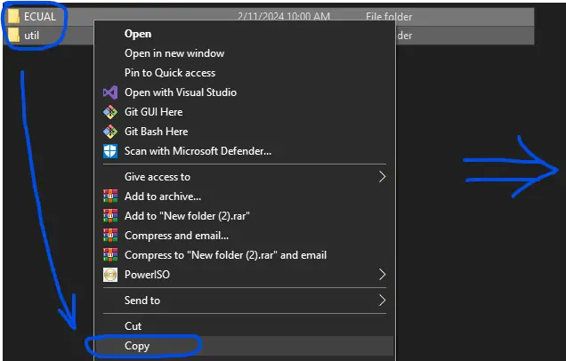
Copy & Paste The Library Folders
Copy the provided library folders (ECUAL/LCD16X2 + util) and open the STM32CubeIDE.
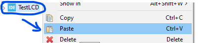
In STM32CubeIDE, right-click the project name and paste the library folders.
 |  | So it’ll look like this at the end: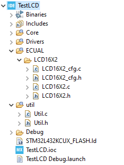 |
Step #3
Add The Library Directories To Paths & Symbols
The library folders have been added to our project but it’s not yet considered as a source code directory, so it won’t be compiled and give you a linking error in the linking stage if you call any of its functions.
Right-click the project name and click Properties. And navigate to C/C++ paths and symbols, and source locations tab. In the source locations tab, click add folder and add our library folders (ECUAL + util).

Step #4
Configure The LCD16X2 Library Using The cfg Parameter
Open the LCD16X2_cfg.c file and modify the configuration parameter items to remap the GPIO pins to match the pins you’ve selected in CubeMX
Step #5
Include The Library Header File & Use it!
Now you’re ready to use the STM32 LCD16X2 library, just include the header file as shown in the test code below.
#include "main.h"
#include "../../ECUAL/LCD16X2/LCD16X2.h"

#define MyLCD LCD16X2_1

void SystemClock_Config(void);
static void MX_GPIO_Init(void);

int main(void)
{
    HAL_Init();
    SystemClock_Config();
    MX_GPIO_Init();

    LCD16X2_Init(MyLCD);
    LCD16X2_Clear(MyLCD);
    LCD16X2_Set_Cursor(MyLCD, 1, 1);
    LCD16X2_Write_String(MyLCD, "  DeepBlue");
    LCD16X2_Set_Cursor(MyLCD, 2, 1);
    LCD16X2_Write_String(MyLCD, "STM32 Course");

    while (1)
    {
    	LCD16X2_SR(MyLCD);  HAL_Delay(1500);
        LCD16X2_SR(MyLCD);  HAL_Delay(1500);
        LCD16X2_SR(MyLCD);  HAL_Delay(1500);
        LCD16X2_SR(MyLCD);  HAL_Delay(1500);

        LCD16X2_SL(MyLCD);  HAL_Delay(1500);
        LCD16X2_SL(MyLCD);  HAL_Delay(1500);
        LCD16X2_SL(MyLCD);  HAL_Delay(1500);
        LCD16X2_SL(MyLCD);  HAL_Delay(1500);
    }
}
STM32 LCD 16×2 Example
Objectives of This STM32 LCD 16×2 Example Project:
- Set up a new project in CubeMX, set the system clock @ 72MHz
- Configure 6x GPIO output pins required by the STM32 LCD16X2 library
- Integrate the STM32 LCD16X2 library as shown in the previous section (step-by-step)
- Write a simple application to test the LCD driver code. Print a couple of strings on line1 and line2 and shift the entire display right and left!
STM32 LCD 16×2 Example Code Project
In this LAB, our goal is to build a system that initializes the LCD driver. Which in turn initializes the configuration-defined GPIO pins and therefore sends the initialization commands to the LCD as described in its datasheet. After this, we can easily call the LCD driver functions to set the cursor position, print strings, and shift the entire display on the LCD right and left. It’s a very basic and simple LAB.
Follow The step-by-step Library Integration Guide shown earlier to create the project and add the LCD16X2 library folders. Copy the example application code below, build the project, and flash it to your STM32 blue pill board.
STM32 LCD 16×2 Example Code
The Application Code For This LAB (main.c)
#include "main.h"
#include "../../ECUAL/LCD16X2/LCD16X2.h"

#define MyLCD LCD16X2_1

void SystemClock_Config(void);
static void MX_GPIO_Init(void);

int main(void)
{
    HAL_Init();
    SystemClock_Config();
    MX_GPIO_Init();

    LCD16X2_Init(MyLCD);
    LCD16X2_Clear(MyLCD);
    LCD16X2_Set_Cursor(MyLCD, 1, 1);
    LCD16X2_Write_String(MyLCD, "  DeepBlue");
    LCD16X2_Set_Cursor(MyLCD, 2, 1);
    LCD16X2_Write_String(MyLCD, "STM32 Course");

    while (1)
    {
    	LCD16X2_SR(MyLCD);  HAL_Delay(450);
        LCD16X2_SR(MyLCD);  HAL_Delay(450);
        LCD16X2_SR(MyLCD);  HAL_Delay(450);
        LCD16X2_SR(MyLCD);  HAL_Delay(450);

        LCD16X2_SL(MyLCD);  HAL_Delay(450);
        LCD16X2_SL(MyLCD);  HAL_Delay(450);
        LCD16X2_SL(MyLCD);  HAL_Delay(450);
        LCD16X2_SL(MyLCD);  HAL_Delay(450);
    }
}
STM32 LCD 16×2 Example Connections

Testing Result (Demo Video)
You can also use the free tool down below to generate your own custom characters and symbols for the LCD display. Things like speaker icon, battery level indicator, and so on.
Custom LCD Character Generator Online Tool
Required Parts For STM32 Examples
All the example Code/LABs/Projects in this STM32 Series of Tutorials are done using the Dev boards & Electronic Parts Below:
| QTY. | Component Name | Amazon.com | AliExpress | eBay |
| 1 | LCD 16×2 Display | Amazon | AliExpress | eBay |
| 1 | STM32-F103 BluePill Board (ARM Cortex-M3 @ 72MHz) | Amazon | AliExpress | eBay |
| 1 | Nucleo-L432KC (ARM Cortex-M4 @ 80MHz) | Amazon | AliExpress | eBay |
| 1 | ST-Link V2 Debugger | Amazon | AliExpress | eBay |
| 2 | BreadBoard | Amazon | AliExpress | eBay |
| 1 | LEDs Kit | Amazon & Amazon | AliExpress | eBay |
| 1 | Resistors Kit | Amazon & Amazon | AliExpress | eBay |
| 1 | Capacitors Kit | Amazon & Amazon | AliExpress & AliExpress | eBay & eBay |
| 1 | Jumper Wires Pack | Amazon & Amazon | AliExpress & AliExpress | eBay & eBay |
| 1 | Push Buttons | Amazon & Amazon | AliExpress | eBay |
| 1 | Potentiometers | Amazon | AliExpress | eBay |
| 1 | Micro USB Cable | Amazon | AliExpress | eBay |
★ Check The Links Below For The Full Course Kit List & LAB Test Equipment Required For Debugging ★
Download Attachments
You can download all attachment files for this Article/Tutorial (project files, schematics, code, etc..) using the link below. Please consider supporting our work through the various support options listed in the link down below. Every small donation helps to keep this website up and running and ultimately supports the whole community.
Wrap Up
In conclusion, we’ve discussed how the STM32 LCD16X2 library works and how to integrate it into your projects and easily configure the LCD GPIO lines. The provided library gives you a handful of useful APIs that you can use in your projects to control a single LCD16X2 unit or multiple display units with no effort.
It’s highly recommended to check the tutorial below to learn about the STM32 I2C LCD interfacing which is a more efficient solution than using GPIO pins as it can save you a lot of IO pins and give you the ability to interface multiple LCD display units using only 2 pins.

This article will give more in-depth information about the I2CLCD display interfacing with STM32 microcontrollers. The provided library is designed to be a very easily portable and configurable software component that’ll definitely help you out in your projects.
If you’re just getting started with STM32, you need to check out the STM32 Getting Started Tutorial here.
Follow this STM32 Series of Tutorials to learn more about STM32 Microcontrollers Programming.
Dear Friend
The file STM32_LCD16x2.rar is broken
Can you please, upload again this file?
Thanks
Claudio
Can you help me, I try to make this circuit in proteus put isn’t work I don’t know why I used STM32F10C6 ..
For my case, RW of LCD must connect to ground.
The LCD is a generic brand.
We hook it to ground to access the LCD in write-only mode. This is totally fine for most applications.
However, if your driver code wanna support read operations from the LCD to the uC, the RW pin shall be connected to an IO pin of the uC.
why the LCD16x2_cfg.h File not include in LCD16x2_cfg.c?
I think must be include or will there is link error!
Yeah, sure. It must be included, i’ll maybe need to check those files
Hi Dear,
thanks a lot for this wonderful tutorial, I’ve follow it step by step but at the end I couldn’t compile but project I got error in the main.c the compilator doesn’t recognize the function LCD_SR() how can I correct it ?
thanks for answers me
Hi and thanks for the amazing library! Just an important note, since your LCD library uses DWT to generate delays, it cannot be used on certain microcontrollers such as STM32F103C4.
Just wanted to point that out so others wouldn’t have to find that after a lot of debugging. Your library worked just fine in STM32F401VC for me.
Thanks for pointing this out. I am using the nucleo-64 STM32F103RBTx to try this example out but I am not getting anything on the display. I may have to replace the DWT delays by something else. I have had good success porting other examples on this site to this nucleo board.
Aha! That’s also understandable since my old LCD library was using the DWT delay which is only available in ARM Cortex M4 onward. That’s why it’s not working on your F103 device.
The new version of my library is now using the internal hardware systick timer for delay generation which is going to work on all STM32 microcontrollers hopefully.
Get the latest version of the library from the GitHub repo and it should work as a charm.
Please, where do I find the wire conections of the LCD to the STM32? Thanks for the content!
Hello Thales, Really sorry if it wasn’t clear in the tutorial itself since the library was updated this year. In the (LCD16X2_cfg.c) file, you’ll find the following structure definition that allows you to choose the 6x pins you want to use for the signals going to the LCD module.
const LCD16X2_CfgType LCD16X2_CfgParam[LCD16X2_MAX] =

{

	{   /*  Configuration Parameter For LCD Instance #1   */

		LCD16X2_1,			/* Index of LCD Instance #1   */

		GPIOA,	GPIO_PIN_2, /* LCD D4 Pin GPIO Port & Pin */

		GPIOA,	GPIO_PIN_3, /* LCD D5 Pin GPIO Port & Pin */

		GPIOA,	GPIO_PIN_4, /* LCD D6 Pin GPIO Port & Pin */

		GPIOA,	GPIO_PIN_5, /* LCD D7 Pin GPIO Port & Pin */

		GPIOA,	GPIO_PIN_6, /* LCD EN Pin GPIO Port & Pin */

		GPIOA,	GPIO_PIN_7  /* LCD RS Pin GPIO Port & Pin */

	}

};
Hi ;
your contents are unique thanks my friend.
It’s usefull to me. Thank you so much!