| Previous Tutorial | Tutorial 42 | Next Tutorial | |||||
| How To Receive SPI Data With STM32 (DMA-Interrupt-Polling) Modes | |||||||
| STM32 Course Home Page ???? | |||||||
In this tutorial, we’ll discuss how to and receive SPI data with STM32 microcontrollers in DMA, Interrupt, and Polling modes. Starting with the SPI Master (Transmitter) firmware project, then I’ll show you the test setup (SPI Master Board -> SPI Slave Board) for the LABs we’ll be doing hereafter.
There are 3 LAB projects to be done in this tutorial to show you how to configure the STM32 SPI Peripheral in Slave mode and receive the incoming data in 3 different modes (polling-interrupt-DMA). Also note that: this tutorial doesn’t have a solution for the case of receiving unknown data length of SPI messages just like the previous UART tutorial. Some solutions to this case for both UART and SPI will be discussed in future tutorials.
In this tutorial: 3 LABs
| LAB 55 | STM32 SPI Slave Data Reception With Polling Mode | ||||||
| LAB 56 | STM32 SPI Slave Data Reception With Interrupt Mode | ||||||
| LAB 57 | STM32 SPI Slave Data Reception With DMA Mode | ||||||
[toc]
Required Components For LABs
All the example code/LABs/projects in the course are going to be done using those boards below.
- Nucleo32-L432KC (ARM Cortex-M4 @ 80MHz) or (eBay)
- Blue Pill STM32-F103 (ARM Cortex-M3 @ 72MHz) or (eBay)
- ST-Link v2 Debugger or (eBay)
| QTY | Component Name | ???? Amazon.com | ???? eBay.com |
| 2 | BreadBoard | Amazon | eBay |
| 1 | LEDs Kit | Amazon Amazon | eBay |
| 1 | Resistors Kit | Amazon Amazon | eBay |
| 1 | Capacitors Kit | Amazon Amazon | eBay & eBay |
| 2 | Jumper Wires Pack | Amazon Amazon | eBay & eBay |
| 1 | 9v Battery or DC Power Supply | Amazon Amazon Amazon | eBay |
| 1 | Micro USB Cable | Amazon | eBay |
| 2 | Push Buttons | Amazon Amazon | eBay |
| 1 | USB-TTL Converter or FTDI Chip | Amazon Amazon | eBay eBay |
★ Check The Full Course Complete Kit List
Some Extremely Useful Test Equipment For Troubleshooting:
- My Digital Storage Oscilloscope (DSO): Siglent SDS1104 (on Amazon.com) (on eBay)
- FeelTech DDS Function Generator: KKMoon FY6900 (on Amazon.com) (on eBay)
- Logic Analyzer (on Amazon.com) (on eBay)
Affiliate Disclosure: When you click on links in this section and make a purchase, this can result in this site earning a commission. Affiliate programs and affiliations include, but are not limited to, the eBay Partner Network (EPN) and Amazon.com.
STM32 SPI Master Data Transmission
After configuring the SPI peripheral in master mode whether in CubeMX or by register-accessing, we can start transmitting data to slave SPI devices. There are some different schemes in order to achieve the data transmission over SPI bus and here are a few of them.
1- SPI Transmitter With Polling
The first method for sending a data buffer over the SPI bus is by using the Polling method which is a blocking piece of code that waits for the current byte to be completely transmitted then it sends the next and so on.
This method is the easiest to implement and the most time-consuming for the CPU which will end up being in the “busy waiting” state for some time unnecessarily.
Here is an example code for sending a data buffer over SPI in the blocking mode (polling)
|
1 2 3 4 |
uint8_t TX_Data[] = "Hello World!"; .. HAL_SPI_Transmit(&hspi1, TX_Data, sizeof(TX_Data), 1); .. |
2- SPI Transmitter With Interrupt
Next, we can use the interrupt signal to free-up some of the CPU time. So it does start the data transmission process and goes to handle other logic parts of the firmware until the transmission completion interrupt signal is fired. Then, the CPU goes to handle the interrupt and sends the next byte of data to be transmitted. And so on!
This way is more efficient than polling the peripheral indeed. However, in some “Time Critical” applications we need everything to be as deterministic, in time, as possible. And a major problem with interrupts is that we can’t expect when it’d arrive or during which task. That can potentially screw up the timing behavior of the system, Especially with an extremely fast communication bus like SPI that can definitely block the CPU if you’re receiving massive data blocks at a very high rate.
Here is an example code for sending a data buffer over SPI in the interrupt mode
|
1 2 3 4 5 6 7 8 9 10 11 12 13 14 15 16 17 18 |
SPI_HandleTypeDef hspi1; uint8_t TX_Data[] = "Hello World!"; int main(void) { .. HAL_SPI_Transmit_IT(&hspi1, TX_Data, sizeof(TX_Data)); .. while (1) { .. } } void HAL_SPI_TxCpltCallback(SPI_HandleTypeDef * hspi) { // TX Done .. Do Something ... } |
3- SPI Transmitter With DMA
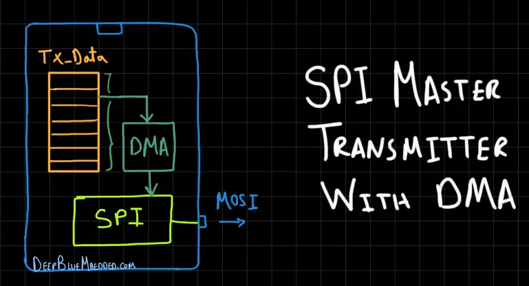
Using the DMA unit not only will make the SPI going at full speed on both sides of communication, but it will also free the CPU from doing the data transfers “from memory to peripheral”. This will end up saving a lot of time and is considered to be the most efficient way to handle this peripheral to memory data transfer and vice versa.
4- SPI Transmitter With Timer Interrupt (Periodic)
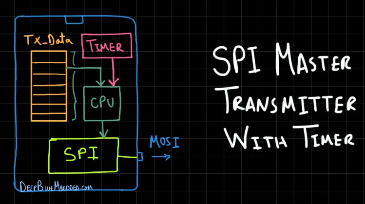
Another way to send serial data is to use a periodic timer interrupt and send the data buffer elements one by one each timer overflow period. That can be configured by the programmer to speed up or slow down the data transmission rate which is another parameter other than the bitrate (baud rate) for the hardware of SPI itself.
This technique is common for low-speed communication if you’re sending readings (data) maybe 1000 times per second or something like that. For example, you’re sending some data to an external SPI DAC chip, the sampling rate can be a few kHz. So, it’d be ideal to use this technique and set up the timer in such a way that achieves the timing you want for the sample period.
Note that this method involves CPU work to service the interrupt signal on-time and access the memory to read the data and send it over SPI. For 10k times or 40k times per second which turns out to be time-consuming and a better way does exist for such a situation as shown next.
5- SPI Transmitter With Timer + DMA (Periodic)
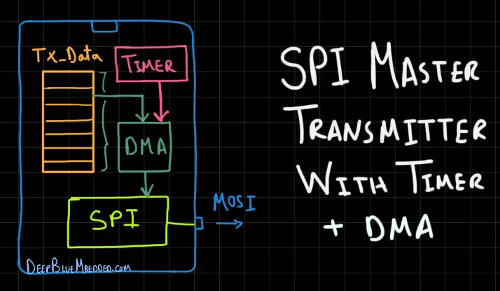
This method is similar to the previous one except it doesn’t need any CPU intervention at all. The DMA unit is responsible for data transfer operations and it gets triggered on-time by the timer overflow signal. You can change the timer period anytime during the code runtime and achieve any sampling rate you want.
This technique has been discussed and implemented in a previous tutorial that you can check out.
STM32 SPI TX-RX Test Setup
Test Setup Overview
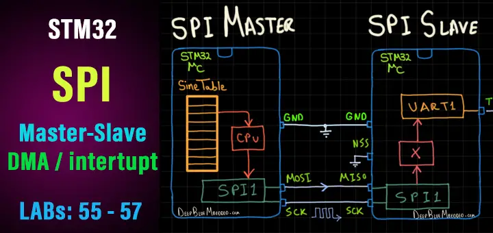
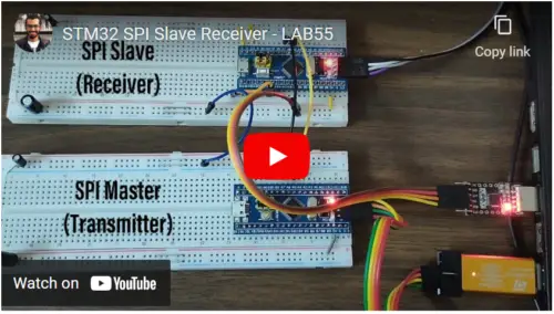
Here is the test setup we’ll be using for today’s 3 LABs. The SPI Master (Transmitter) is going to be STM32F103C8T6 and another one will be acting as an SPI Slave (Receiver). The data to be Sent/Received is going to be a “Sine Table” in string format.
The SPI Master will send the table elements one by one until completion. The SPI Slave will receive that incoming data byte by byte and print them over through a UART port to the PC. And we’ll open a serial plotter at the PC to see the incoming data that should be a complete cycle sine waveform.
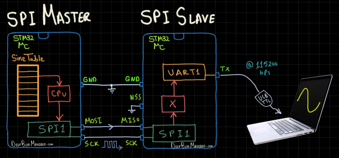
As you can see in the diagram above, there will be 2 STM32 SPI devices connected together. The first one is a Master SPI that will send out a buffer of data “Sine Table”. The other device is an SPI Slave that will receive the incoming SPI data and send it out over the UART port to a PC. The slave device will receive the SPI data using (Polling, interrupt, DMA) and send it out after the reception.
However, on the slave side, you can direct the incoming data from SPI to UART using DMA or maybe with polling or interrupt as well. In this case, you can use a short buffer and send the data out over UART will you’re receiving them through SPI. Any implementation will still get the task done.
Sine Table Data Buffer
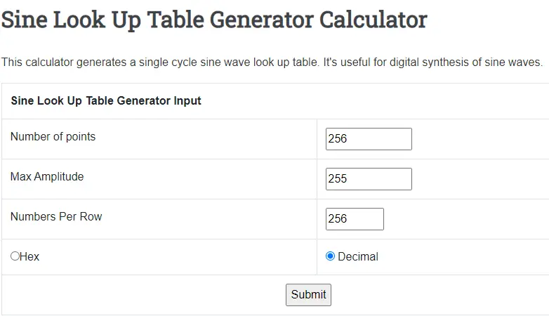
You can use a MATLAB script to generate the sine table data points or use this Online Sine Lookup Table Generator Tool. I want the maximum value to be 255, will generate 256 data points for the complete cycle, make numbers in the decimal format, and will get them printed in a single line to be easier for the next processing.
 |
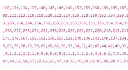 |
Copy the text that has been generated to any word processor like LibreOffice. And there you’ll need to click edit and choose the “Find and Replace” tool. Then replace every comma “,” with a “\r\n” so that we can easily plot that data when it’s received at the PC side.


We’ll be using “Arduino Serial Plotter” to plot those points when the slave has successfully received the data and transmitted it back over the UART port.
The total string length is now 1652 bytes. This is going to be a global variable at the SPI master device, so it’s going to take up a lot of the flash memory when it’s flashing and the data buffer will be initialized in RAM during startup. That’s a lot of memory indeed but anyway it’s a tester code. We want to test the receiver functionality and not really concerned about the master device.
STM32 SPI Master (TX) Project
Step1: Open CubeMX & Create New Project
Step2: Choose The Target MCU & Double-Click Its Name
STM32F103C8T6 (the one I’ll be using) or any other STM32 part you’ve got
Step3: Go To The RCC Clock Configuration
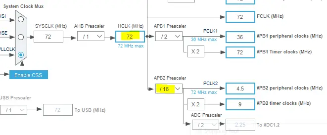
Step4: Set The System Clock To Be 70MHz or whatever your uC board supports
And set the APB2 bus clock Prescaler to 16 or whatever value that makes the SPI bit rate a little bit lower than the UART baud rate just to give the slave SPI devices enough headroom to be able to send out the data packets they will receive.
Step5: Enable The SPI Module (Transmitter Only Master Mode)
Just remember the settings for this transmitter SPI device because you’ll have to have similar settings for the slave device as well. The clock edge, polarity, and data size and order. The clock rate is only important for the master device. The SPI slave clock rate value is neglected.
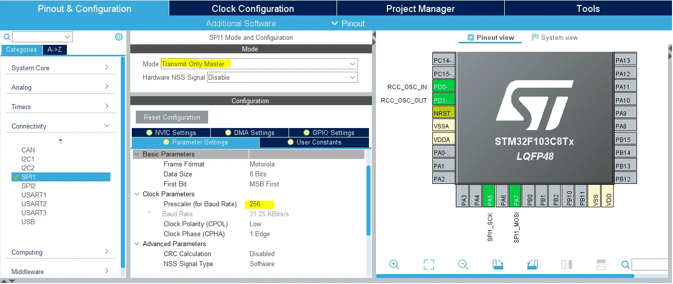
Step6: Generate The Initialization Code & Open The Project In Your IDE
Now, we can start developing our application in the main.c source file.
Here is The Application Code For The SPI Master Device (main.c)
|
1 2 3 4 5 6 7 8 9 10 11 12 13 14 15 16 17 18 19 20 21 22 23 24 25 26 |
#include "main.h" SPI_HandleTypeDef hspi1; uint8_t TX_Data[] = "128\r\n131\r\n134\r\n137\r\n140\r\n143\r\n146\r\n149\r\n152\r\n155\r\n158\r\n162\r\n165\r\n167\r\n170\r\n173\r\n176\r\n179\r\n182\r\n185\r\n188\r\n190\r\n193\r\n196\r\n198\r\n201\r\n203\r\n206\r\n208\r\n211\r\n213\r\n215\r\n218\r\n220\r\n222\r\n224\r\n226\r\n228\r\n230\r\n232\r\n234\r\n235\r\n237\r\n238\r\n240\r\n241\r\n243\r\n244\r\n245\r\n246\r\n248\r\n249\r\n250\r\n250\r\n251\r\n252\r\n253\r\n253\r\n254\r\n254\r\n254\r\n255\r\n255\r\n255\r\n255\r\n255\r\n255\r\n255\r\n254\r\n254\r\n254\r\n253\r\n253\r\n252\r\n251\r\n250\r\n250\r\n249\r\n248\r\n246\r\n245\r\n244\r\n243\r\n241\r\n240\r\n238\r\n237\r\n235\r\n234\r\n232\r\n230\r\n228\r\n226\r\n224\r\n222\r\n220\r\n218\r\n215\r\n213\r\n211\r\n208\r\n206\r\n203\r\n201\r\n198\r\n196\r\n193\r\n190\r\n188\r\n185\r\n182\r\n179\r\n176\r\n173\r\n170\r\n167\r\n165\r\n162\r\n158\r\n155\r\n152\r\n149\r\n146\r\n143\r\n140\r\n137\r\n134\r\n131\r\n128\r\n124\r\n121\r\n118\r\n115\r\n112\r\n109\r\n106\r\n103\r\n100\r\n97\r\n93\r\n90\r\n88\r\n85\r\n82\r\n79\r\n76\r\n73\r\n70\r\n67\r\n65\r\n62\r\n59\r\n57\r\n54\r\n52\r\n49\r\n47\r\n44\r\n42\r\n40\r\n37\r\n35\r\n33\r\n31\r\n29\r\n27\r\n25\r\n23\r\n21\r\n20\r\n18\r\n17\r\n15\r\n14\r\n12\r\n11\r\n10\r\n9\r\n7\r\n6\r\n5\r\n5\r\n4\r\n3\r\n2\r\n2\r\n1\r\n1\r\n1\r\n0\r\n0\r\n0\r\n0\r\n0\r\n0\r\n0\r\n1\r\n1\r\n1\r\n2\r\n2\r\n3\r\n4\r\n5\r\n5\r\n6\r\n7\r\n9\r\n10\r\n11\r\n12\r\n14\r\n15\r\n17\r\n18\r\n20\r\n21\r\n23\r\n25\r\n27\r\n29\r\n31\r\n33\r\n35\r\n37\r\n40\r\n42\r\n44\r\n47\r\n49\r\n52\r\n54\r\n57\r\n59\r\n62\r\n65\r\n67\r\n70\r\n73\r\n76\r\n79\r\n82\r\n85\r\n88\r\n90\r\n93\r\n97\r\n100\r\n103\r\n106\r\n109\r\n112\r\n115\r\n118\r\n121\r\n124\r\n"; void SystemClock_Config(void); static void MX_GPIO_Init(void); static void MX_SPI1_Init(void); int main(void) { HAL_Init(); SystemClock_Config(); MX_GPIO_Init(); MX_SPI1_Init(); // Send The TX Data Buffer (Blocking Mode) HAL_SPI_Transmit(&hspi1, TX_Data, sizeof(TX_Data), 5000); while (1) { } } |
Download The STM32 SPI Master Transmitter (Blocking)
Compile the project and flash the code to the SPI Master device board. And now, we’ll get ready to do the SPI receiver projects (in 3 modes).
STM32 SPI Slave Receiver Polling Mode – LAB
| LAB Number | 55 |
| LAB Title | STM32 SPI Slave Data Reception With Polling Mode |
Step1: Open CubeMX & Create New Project
Step2: Choose The Target MCU & Double-Click Its Name
STM32F103C8T6 (the one I’ll be using) or any other STM32 part you’ve got
Step3: Go To The RCC Clock Configuration
Step4: Set The System Clock To Be 70MHz or whatever your uC board supports
Step5: Enable The SPI Module (Receiver Only Slave Mode)
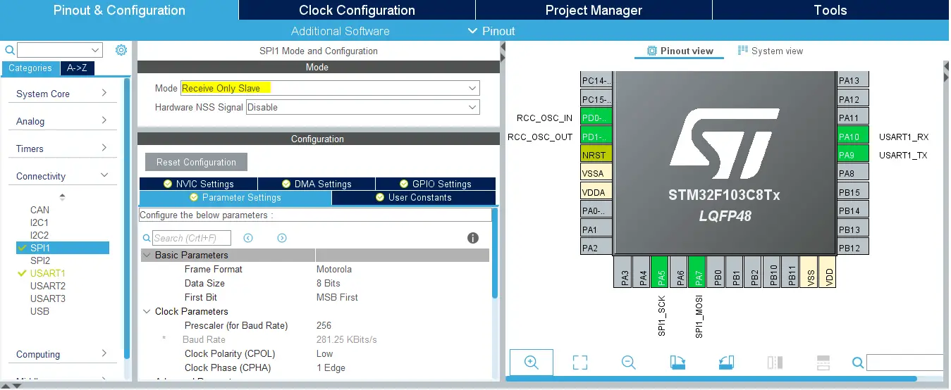
Step6: Enable Any UART Module (Async Mode) @ 115200 bps
Step7: Generate The Initialization Code & Open The Project In Your IDE
Now, we can start developing our application in the main.c source file.
At this point, we can pretend as if we don’t know that incoming SPI data length from the master device and we’d make the receiver buffer large enough to get all the incoming data bytes and set the timeout to any reasonable value after which we’ll stop SPI reception and start processing the available data, if any, has been received.
Otherwise, we can just make a buffer with the same size as the incoming string. In the next 2 LABs, we’ll see another way to do this assuming data length is unknown.
Here is The Application Code For This LAB (main.c)
|
1 2 3 4 5 6 7 8 9 10 11 12 13 14 15 16 17 18 19 20 21 22 23 24 25 26 27 28 29 |
#include "main.h" SPI_HandleTypeDef hspi1; UART_HandleTypeDef huart1; uint8_t RX_Data[1652] = {0}; void SystemClock_Config(void); static void MX_GPIO_Init(void); static void MX_SPI1_Init(void); static void MX_USART1_UART_Init(void); int main(void) { HAL_Init(); SystemClock_Config(); MX_GPIO_Init(); MX_SPI1_Init(); MX_USART1_UART_Init(); // Receive SPI Data (Blocking Mode) Polling HAL_SPI_Receive(&hspi1, RX_Data, sizeof(RX_Data), 5000); HAL_UART_Transmit(&huart1, RX_Data, sizeof(RX_Data), 5000); while (1) { } } |
Download The STM32 SPI Slave Receiver (Polling) – LAB55
The Result For This LAB Testing (Video)
I did restart the slave device first, then restart the transmitter and wait for the 1.6Kbytes to be completely received over SPI and sent over UART to my PC. The Arduino Serial Plotter did catch all the data bytes successfully and the result is a pretty sine wave.
Then, I did restart both devices again. The slave then the master shortly before the 5sec timeout is over. And the result was another sine wave cycle as you can see in the demo video down below.
STM32 SPI Slave Receiver Interrupt Mode – LAB
| LAB Number | 56 |
| LAB Title | STM32 SPI Slave Data Reception With Interrupt Mode |
Step1: Open CubeMX & Create New Project
Step2: Choose The Target MCU & Double-Click Its Name
STM32F103C8T6 (the one I’ll be using) or any other STM32 part you’ve got
Step3: Go To The RCC Clock Configuration
Step4: Set The System Clock To Be 70MHz or whatever your uC board supports
Step5: Enable The SPI Module (Receiver Only Slave Mode) + Enable NVIC Interrupt For SPI

Step6: Enable Any UART Module (Async Mode) @ 115200 bps + Enable UART Interrupt in NVIC tab
Step7: Generate The Initialization Code & Open The Project In Your IDE
Now, we can start developing our application in the main.c source file.
At this point, we can pretend as if we don’t know the incoming SPI data length from the master device and we’d make the receiver buffer may be 100 bytes. Whenever 100 bytes are received by SPI in interrupt mode, the Rx completion callback function is called. At which, we’ll process the received data and repeat to get the next 100 bytes.
The issue with this approach is we’ll be receiving a total of 1652 bytes. After 16 callbacks we’ll have received and processed 1600 bytes of data. There will be 52 bytes remaining. The SPI will receive those bytes in interrupt mode. But the application will not be notified as the callback function gets called only when the provided buffer (100 bytes) is full.
Those remaining 52 bytes won’t be lost or anything. They’ll roll over to the next communication session. If we did restart the master device, it’ll attempt to send another 1652bytes data packet. After getting the first 48 bytes, the Rx callback will be called because there are already another 52 bytes in the buffer from the last communication session. So it’s ok!
In other applications, you may need to be notified when a complete message is received whatever its length is. And in this case, it should have a special termination like “\r\n” or anything like that. And this will be a topic for a dedicated article to address the common question of “receiving unknown data length over SPI or UART”.
Here is The Application Code For This LAB (main.c)
|
1 2 3 4 5 6 7 8 9 10 11 12 13 14 15 16 17 18 19 20 21 22 23 24 25 26 27 28 29 30 31 32 33 34 35 |
#include "main.h" #define BUFFER_SIZE 100 SPI_HandleTypeDef hspi1; UART_HandleTypeDef huart1; uint8_t RX_Buffer[BUFFER_SIZE] = {0}; void SystemClock_Config(void); static void MX_GPIO_Init(void); static void MX_SPI1_Init(void); static void MX_USART1_UART_Init(void); int main(void) { HAL_Init(); SystemClock_Config(); MX_GPIO_Init(); MX_SPI1_Init(); MX_USART1_UART_Init(); HAL_SPI_Receive_IT(&hspi1, RX_Buffer, BUFFER_SIZE); while (1) { } } void HAL_SPI_RxCpltCallback(SPI_HandleTypeDef * hspi) { HAL_SPI_Receive_IT(&hspi1, RX_Buffer, BUFFER_SIZE); HAL_UART_Transmit_IT(&huart1, RX_Buffer, BUFFER_SIZE); } |
Download The STM32 SPI Slave Receiver (Interrupt) – LAB56
The Result For This LAB Testing (Video)
As you can see in the test demo video down below, we’ve successfully received the incoming data over SPI. And it has been sent to the PC over UART in batches of 100 bytes. The first 1600 was plotted on the monitor and we’re missing the last 52 bytes which have been shown as an in-complete sine wave cycle.
Then, I did restart the Master SPI device to attempt sending another packet of 1652 byte for the next cycle. And as you can see, the last 52 bytes were kept in the buffer. Otherwise, there should have been a glitch in the waveform. It’s easy to visually spot a communication error in this test setup because it’ll show up as a glitch in the sinusoidal waveform.
STM32 SPI Slave Receiver With DMA Mode – LAB
| LAB Number | 57 |
| LAB Title | STM32 SPI Slave Data Reception With DMA Mode |
Step1: Open CubeMX & Create New Project
Step2: Choose The Target MCU & Double-Click Its Name
STM32F103C8T6 (the one I’ll be using) or any other STM32 part you’ve got
Step3: Go To The RCC Clock Configuration
Step4: Set The System Clock To Be 70MHz or whatever your uC board supports
Step5: Enable The SPI Module (Receiver Only Slave Mode) + Enable DMA Channel For SPI With its NVIC Interrupt

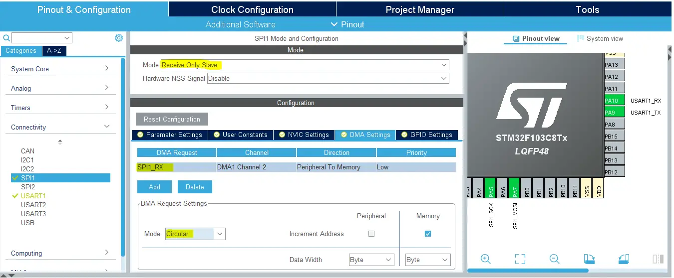
Step6: Enable Any UART Module (Async Mode) @ 115200 bps + Enable UART Interrupt in NVIC tab
Step7: Generate The Initialization Code & Open The Project In Your IDE
Now, we can start developing our application in the main.c source file.
|
1 2 3 4 5 6 7 8 9 10 11 12 13 14 15 16 17 18 19 20 21 22 23 24 25 26 27 28 29 30 31 32 33 34 35 36 37 38 |
#include "main.h" #define BUFFER_SIZE 100 SPI_HandleTypeDef hspi1; DMA_HandleTypeDef hdma_spi1_rx; UART_HandleTypeDef huart1; uint8_t RX_Buffer[BUFFER_SIZE] = {0}; void SystemClock_Config(void); static void MX_GPIO_Init(void); static void MX_DMA_Init(void); static void MX_SPI1_Init(void); static void MX_USART1_UART_Init(void); int main(void) { HAL_Init(); SystemClock_Config(); MX_GPIO_Init(); MX_DMA_Init(); MX_SPI1_Init(); MX_USART1_UART_Init(); HAL_SPI_Receive_DMA(&hspi1, RX_Buffer, BUFFER_SIZE); while (1) { } } void HAL_SPI_RxCpltCallback(SPI_HandleTypeDef * hspi) { HAL_SPI_Receive_DMA(&hspi1, RX_Buffer, BUFFER_SIZE); HAL_UART_Transmit_IT(&huart1, RX_Buffer, BUFFER_SIZE); } |
Download The STM32 SPI Slave Receiver (DMA) – LAB57
The Result For This LAB Testing (Video)
It did work exactly like the previous lab (interrupt mode)
Concluding Remarks
We’ve done SPI data transmission and reception in 3 different modes. And demonstrated the difference between all of them. Whether by creating a large-enough RX buffer given the number of bytes to be received or by acting as if we don’t know the length of the incoming data. Both ways did work just as fine.
What I’ve commonly seen in the comments here on my website and other places online is an issue that happens with a lot of programmers while receiving any incoming data with STM32 microcontrollers over SPI or UART with unknown data length. How to notify my application at the end of each message?
Like GNSS (GPS) strings and other string-based communications. How long should the RX buffer be and how to work around this issue?
Fortunately, the UART hardware in STM32 microcontrollers does provide a feature called IDLE line detection. That can potentially be used to report “end of communication session”. That would mean we’ve successfully received a complete message whatever its length. Is it the only way to solve this problem?
On the other hand, SPI doesn’t have such a feature.
All of that and more will be discussed in detail with some different solutions and techniques in a future tutorial or two for both UART and SPI.
I’d really like to read your thoughts about this topic and how would you solve this problem given that your application can’t process the data partially. If you could notice in my LABs, the data is easily processed partially and I didn’t need to wait for all the incoming 1652 bytes to be received as I can process them “in batches”. So this issue doesn’t arise in this category of applications.
Did you find this helpful? If yes, please consider supporting this work and sharing these tutorials!
Stay tuned for the upcoming tutorials and don’t forget to SHARE these tutorials. And consider SUPPORTING this work to keep publishing free content just like this!
| Previous Tutorial | Tutorial 42 | Next Tutorial | |||||

Thank you for your posts, very interesting.
I have two signal one is a clock about 12MHz and other is data which I need to sample at clock / 128.
Every byte is trasmitted with 10 bit.
Can I use spi module for this operation? I’d like use SPI for I can receive with DMA.
Another solution is sampling the digital pin when I have an overflow (128) on a timer which is clocked by clock signal.
With second solution microcontroller should always work, while with the first solution the microcontroller work only when there is an interrupt data is received from spi.