| Previous Tutorial | Tutorial 28 | Next Tutorial | |||||
| STM32 DAC Waveform Generation (Sine, Sawtooth, Sinc, etc) | |||||||
| STM32 Course Home Page ???? | |||||||
In this LAB, we’ll discuss how to generate analog waveforms like (sine, sawtooth, triangular, etc) using STM32 DAC with DMA transfer. And how to control the output waveform frequency. And also how to generate the waveform lookup table points for each function using MATLAB. Let’s get right into it!
[toc]
Required Components For LABs
All the example code/LABs/projects in the course are going to be done using those boards below.
- Nucleo32-L432KC (ARM Cortex-M4 @ 80MHz) or (eBay)
- Blue Pill STM32-F103 (ARM Cortex-M3 @ 72MHz) or (eBay)
- ST-Link v2 Debugger or (eBay)
| QTY | Component Name | ???? Amazon.com | ???? eBay.com |
| 2 | BreadBoard | Amazon | eBay |
| 1 | LEDs Kit | Amazon Amazon | eBay |
| 1 | Resistors Kit | Amazon Amazon | eBay |
| 1 | Capacitors Kit | Amazon Amazon | eBay & eBay |
| 2 | Jumper Wires Pack | Amazon Amazon | eBay & eBay |
| 1 | 9v Battery or DC Power Supply | Amazon Amazon Amazon | eBay |
| 1 | Micro USB Cable | Amazon | eBay |
| 1 | Push Buttons | Amazon Amazon | eBay |
★ Check The Full Course Complete Kit List
Some Extremely Useful Test Equipment For Troubleshooting:
- My Digital Storage Oscilloscope (DSO): Siglent SDS1104 (on Amazon.com) (on eBay)
- FeelTech DDS Function Generator: KKMoon FY6900 (on Amazon.com) (on eBay)
- Logic Analyzer (on Amazon.com) (on eBay)
Affiliate Disclosure: When you click on links in this section and make a purchase, this can result in this site earning a commission. Affiliate programs and affiliations include, but are not limited to, the eBay Partner Network (EPN) and Amazon.com.
STM32 DAC For Waveform Generation
As we’ve seen in the previous tutorial, the DAC peripheral in STM32 microcontrollers can be easily configured to output analog voltage that corresponds to the digital output value written to the DOR register. Hence, generating analog waveforms is nothing more than writing out the waveform data points from somewhere in the memory to the DAC output register. This process can be divided into two major steps:
Step1: Generating The Lookup Table
The lookup table is an array of unsigned integer values that represents the sample points of a specific waveform for a complete cycle (from 0 to 2π). The length of the lookup table is denoted as Ns or the number of sample points per complete cycle. The more sample points per cycle, the better the output waveform.
We’ll be using MATLAB script for generating the sample points lookup table for various waveforms as we’ll see in the next section. Afterward, we’ll copy it to our code so that the Wave_LUT[NS] array is ready to be transferred to the DAC output.
Step2: Moving The Data To The DAC Output
There exist a number of different ways in order to transfer some data points from the memory to the DAC output. The first of which is by using the CPU power itself. We can loop through the lookup table and send the waveform sample points one by one to the DAC output. However, this method is so bad for loading the CPU and consuming 100% of its time. Moreover, any CPU interrupts or going to handle other tasks will distort the timing of the output signal for the DAC. This is obviously not a very good idea, despite the fact that it works (in very limited situations). And in this case, the output waveform’s frequency is controlled by changing the delay period (x).
|
1 2 3 4 5 |
while(1) { DAC_Out(Wave_LUT[i++]); DWT_Delay_us(x); } |
Another way is to use Timer interrupts to periodically fire an interrupt signal so that the CPU can transfer the data points to the DAC in a periodic manner. However, it’s a more efficient way than the previous one. But it still requires a lot of CPU intervention, especially when a high sampling rate is required. Sometimes it can be unachievable at all or achievable but loads the CPU by 60% or more. Which is also not a very good idea. Despite the fact that it does work and better than the previous method.
Lastly, we can use the DMA & Timer to periodically trigger the DMA unit so that it moves a sample data point from the lookup table stored in memory to the DAC output. Each time the timer trigger event occurs, the DMA transfers a data point from the table to the DAC output and increments the memory pointer to move the next data point in the next trigger event. This method is the best way to achieve the task without any CPU intervention.
The DMA can also be configured to operate in the circular mode so that it wraps around the lookup table every time it reaches the end of the table. Therefore, no action is required by the CPU at all. And this is what we’re going to implement in this LAB today.
Generating The Waveform Lookup Table
There are many ways to generate a lookup table for any waveform you want. One of which is calculating the data points in the runtime using the CPU of the target itself. You power up the system, the CPU starts calculating the sine function points for example, and store them in the Wave_LUT[] array and use it afterward.
You can also use an online calculator like this one. Define the number of points you want and the maximum amplitude (defined by your DAC’s resolution), and generate the table. Copy and paste it into your code and you’re good to go.
Online Sine LookUp Table Generator Tool
Alternatively, you can use a MATLAB script to generate and print the waveform sample points. You can configure the script below to set the required sample points number (Ns) and give it an offset from 0 in case you want that. And also the resolution of the DAC in your system (in bits).
Here is the MATLAB script that generates the lookup table for you.
|
1 2 3 4 5 6 7 8 9 10 11 12 13 14 15 16 17 18 19 |
clear; clc; % Clear The Previous Points Ns = 128; % Set The Number of Sample Points RES = 12; % Set The DAC Resolution OFFSET = 0; % Set An Offset Value For The DAC Output %------------[ Calculate The Sample Points ]------------- T = 0:((2*pi/(Ns-1))):(2*pi); Y = sin(T); Y = Y + 1; Y = Y*((2^RES-1)-2*OFFSET)/(2+OFFSET); Y = round(Y); plot(T, Y); grid %--------------[ Print The Sample Points ]--------------- fprintf('%d, %d, %d, %d, %d, %d, %d, %d, %d, %d, %d, %d, %d, %d, %d, \n', Y); %-------------------[ Other Examples To Try ]------------------- % Y = diric(T, 13); % Periodic Sinc % Y = sawtooth(T) % Sawtooth % Y = sawtooth(T, 0.5); % Triangular |
The waveform can be changed by adjusting the function calculation line. Three examples are commented at the end of the script. A periodic sinc function, sawtooth, and a triangular waveform.
DAC DMA Sine Waveform Generation
Now, we’ve got the waveform lookup table and also decided to use the DMA triggered by a timer in order to move the data points from the lookup table to the DAC output. The question is, how to calculate & control the output waveform frequency?
Let’s say we’ve generated a sinewave lookup table with 128 sample points (Ns), and configured Timer2 so it triggers the DMA transfer to the DAC output. What would be the output sine wave frequency?
Here are the formulas to be used
![]()
Where FCLK is the frequency of the clock used by your timer module, PSC is the Prescaler, and ARR is the value of the auto-reload register.
![]()
Where Ns is the sample points number in the lookup table.
For example, let’s assume the following settings:
The FCLK is 80MHz, the PSC is 0, ARR is 1000, and the sine lookup table has 128 sample points. What would be the output sine wave frequency?
TriggerFrequency = 80MHz / 1001 = 79920.08
Output Sinewave Frequency = TriggerFrequency / 128 = 624.37 Hz
For example, let’s assume the following settings:
an output sine wave is required to be generated with a frequency of 1kHz
The FCLK is 80MHz, and the sine lookup table has 128 sample points. What would be the timer configurations?
Output SineWave Frequency = Trigger frequency / 128
1KHz = TriggerFrequency / 128
TriggerFrequency = 128KHz
TriggerFrequency = 80MHz / (PSC+1)(ARR+1)
128KHz = 80MHz / (PSC+1)(ARR+1)
let’s choose PSC = 0, and solve for ARR
ARR will therefore be ARR = 624
STM32 DAC WaveForm Generator – LAB23
| LAB Number | 23 |
| LAB Title | STM32 DAC DMA Waveform Generation |
- Set up a new project as usual with system clock @ 80MHz
- Set up the DAC1 peripheral to work in normal mode with output buffer enabled
- Use the provided MATLAB script to generate lookup tables to be used for this LAB
- Setup timer2 to be the trigger source for DMA1 unit
- Setup DMA1 to move data from memory to DAC peripheral
- Generate a 1KHz sine waveform. Change the lookup table data to make it sawtooth, triangular, sinc functions
And now, let’s build this system step-by-step
Step1: Open CubeMX & Create New Project
Step2: Choose The Target MCU & Double-Click Its Name
STM32L432KC
Step3: Go To The Clock Configuration
Step4: Set The System Clock To Be 80MHz
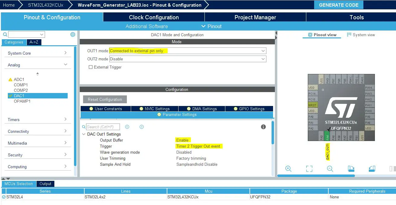
Step5: Enable The DAC1 Output In Normal Mode & Buffer Enable
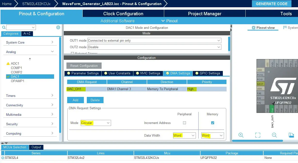
Step6: Enable The DAC1 DMA Channel & Configure It As Shown Below
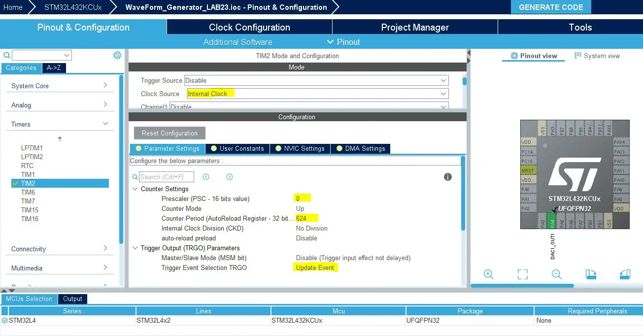
Step7: Now, Configure Timer2 Peripheral As Shown
Do you remember the example of the calculation shown earlier in this article? Where we want to generate a 1kHz sine wave with a system clock of 80MHz and lookup table with 128 entries.
The PCS was chosen to be 0, and the ARR was calculated to be 624. That’s what we’re doing here in this step.
Step8: Generate The Initialization Code & Open The Project In Your IDE
Here is The Application Code For This LAB (main.c)
|
1 2 3 4 5 6 7 8 9 10 11 12 13 14 15 16 17 18 19 20 21 22 23 24 25 26 27 28 29 30 31 32 33 34 35 36 37 38 39 40 41 42 |
#include "main.h" #define NS 128 uint32_t Wave_LUT[NS] = { 2048, 2149, 2250, 2350, 2450, 2549, 2646, 2742, 2837, 2929, 3020, 3108, 3193, 3275, 3355, 3431, 3504, 3574, 3639, 3701, 3759, 3812, 3861, 3906, 3946, 3982, 4013, 4039, 4060, 4076, 4087, 4094, 4095, 4091, 4082, 4069, 4050, 4026, 3998, 3965, 3927, 3884, 3837, 3786, 3730, 3671, 3607, 3539, 3468, 3394, 3316, 3235, 3151, 3064, 2975, 2883, 2790, 2695, 2598, 2500, 2400, 2300, 2199, 2098, 1997, 1896, 1795, 1695, 1595, 1497, 1400, 1305, 1212, 1120, 1031, 944, 860, 779, 701, 627, 556, 488, 424, 365, 309, 258, 211, 168, 130, 97, 69, 45, 26, 13, 4, 0, 1, 8, 19, 35, 56, 82, 113, 149, 189, 234, 283, 336, 394, 456, 521, 591, 664, 740, 820, 902, 987, 1075, 1166, 1258, 1353, 1449, 1546, 1645, 1745, 1845, 1946, 2047 }; DAC_HandleTypeDef hdac1; DMA_HandleTypeDef hdma_dac_ch1; TIM_HandleTypeDef htim2; void SystemClock_Config(void); static void MX_GPIO_Init(void); static void MX_DMA_Init(void); static void MX_DAC1_Init(void); static void MX_TIM2_Init(void); int main(void) { HAL_Init(); SystemClock_Config(); MX_GPIO_Init(); MX_DMA_Init(); MX_DAC1_Init(); MX_TIM2_Init(); HAL_DAC_Start_DMA(&hdac1, DAC_CHANNEL_1, (uint32_t*)Wave_LUT, 128, DAC_ALIGN_12B_R); HAL_TIM_Base_Start(&htim2); while (1) { } } |
Download The STM32 DAC WaveForm Generator LAB23
The Result For This LAB Testing On My DSO
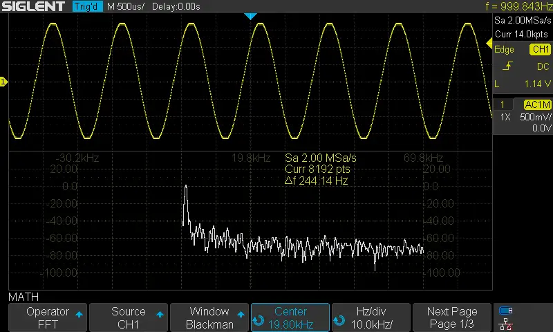
Here is the result for the first test (sine wave @ 1KHz)
The FFT shows a THD of nearly 1 or 2% which is not bad. And can be improved by increasing the sample points and adding an offset so that the signal doesn’t swing to the extreme ends.
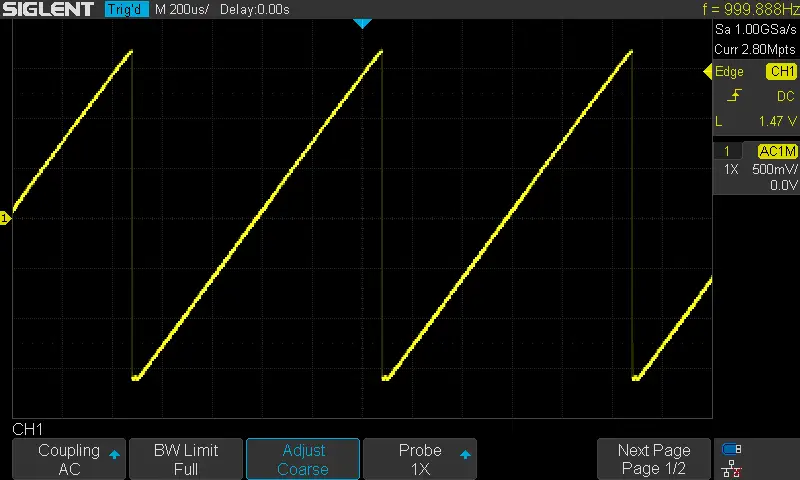
Here is the result for the 2nd test (sawtooth wave @ 1KHz)
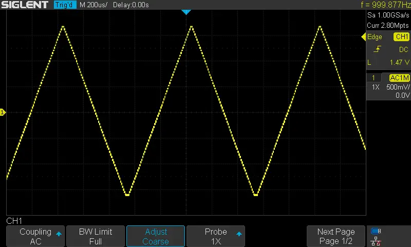
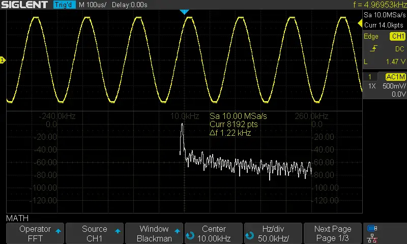
Here is the result for the 3rd test (triangular wave @ 1KHz)
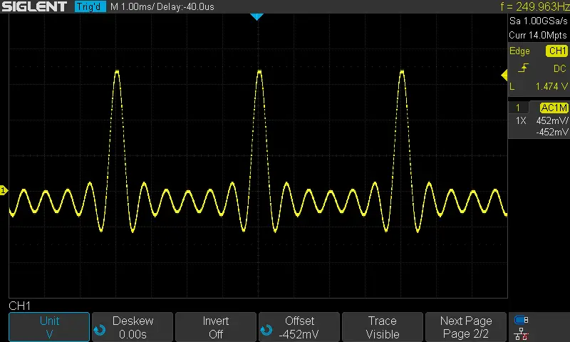
Here is the result for the 4th test “The Beautiful Sinc Function”
Here is the result for the 5th test (sine wave @ 5KHz)
By writing 125 to the Timer2 ARR, we’d expect the sine output signal’s frequency to increase to 5KHz. And that’s exactly what happens.
Did you find this helpful? If yes, please consider supporting this work and sharing these tutorials!
Stay tuned for the upcoming tutorials and don’t forget to SHARE these tutorials. And consider SUPPORTING this work to keep publishing free content just like this!
| Previous Tutorial | Tutorial 28 | Next Tutorial | |||||