
In this tutorial, we’ll discuss the STM32 PWM output generation using STM32 timer modules in the PWM mode. You’ll learn how the PWM signal is generated, how to control its frequency, duty cycle, and how to estimate the PWM resolution. And how to set up the timer module to operate in PWM mode and write a simple STM32 PWM Example Code (LED dimmer). And without further ado, let’s get right into it!
Table of Contents
- STM32 PWM Introduction
- STM32 PWM Mode in Timer Explained
- STM32 PWM HAL Functions
- STM32 PWM Output Example LED Dimmer
- STM32 PWM Example LED Dimmer
- STM32 PWM Wrap-Up
STM32 PWM Introduction
Pulse Width Modulation (PWM) is a technique for generating a continuous HIGH/LOW alternating digital signal and programmatically controlling its pulse width and frequency. Certain loads like (LEDs, Motors, etc) will respond to the average voltage of the signal which gets higher as the PWM signal’s pulse width is increased. This technique is widely used in embedded systems to control LEDs brightness, motor speed, and other applications.
PWM Frequency
The PWM signal captures a few features. The first of which is the frequency, which is basically a measure of how fast the PWM signal keeps alternating between HIGH and LOW. The frequency is measured in Hz and it’s the inverse of the full period time interval. Here is how it looks graphically and its mathematical formula.

PWM Duty Cycle
The PWM’s duty cycle is the most important feature that we’re always interested in. It’s a measure of how long the PWM signal stays ON relative to the full PWM’s cycle period. The PWM’s duty cycle equation is as follows:

The duty cycle is usually expressed as a percentage (%) value because it’s a ratio between two-time quantities. And it directly affects the PWM’s total (average) voltage that most devices respond to. That’s why we typically change the duty cycle to control things like LED brightness, DC motor speed, etc.
PWM Resolution
The PWM resolution is expressed in (bits). It’s the number of bits that are used to represent the duty cycle value. It can be 8bits, 10, 12, or even 16bits. The PWM resolution can be defined as the number of discrete duty cycle levels between 0% and 100%. The higher the PWM resolution, the higher the number of discrete levels over the entire range of the PWM’s duty cycle.
A PWM resolution of only 3 bits means there are only 8 discrete levels for the duty cycle over the entire range (from 0% up to 100%). On the other hand, a PWM with a resolution of 8 bits will have 256 discrete levels for the duty cycle over the entire range (from 0% up to 100%). You can use the interactive tool below to test this yourself.
Average voltage:
PWM Duty Cycle:
50%
PWM Frequency:
x Hz
PWM Duty Cycle Resolution:
Set the PWM resolution to 3-bit and sweep across the entire range of PWM's duty cycle. And change the resolution up to 8 bits or even 16 bits to see the huge difference in the degree of control you'll have over the duty cycle value. It becomes incredibly smooth as the resolution increases and we become more able to fine-tune the duty cycle. You can use the keyboard arrow keys for fine adjustment of the duty cycle while testing high resolutions.
After playing around with the interactive tool above, you can easily tell that a higher PWM resolution is always a desirable thing to have. However, it's always in inverse proportion to the PWM's frequency. The higher the PWM frequency you choose, the lower the PWM resolution becomes. There is no way to go around this fact.
STM32 PWM Mode in Timer Explained
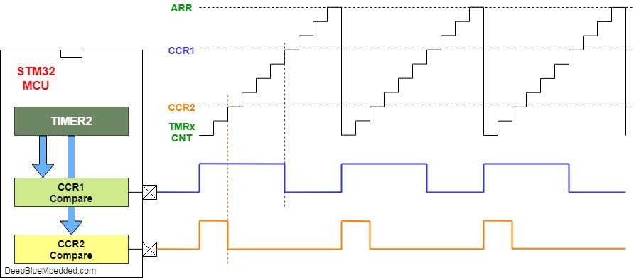
As we've discussed in an earlier tutorial, the STM32 timer modules can operate a variety of modes one of which is the PWM mode. Where the timer gets clocked from an internal source and counts up to the auto-reload register value, then the output channel pin is driven HIGH. And it remains until the timer counts reach the CCRx register value, the match event causes the output channel pin to be driven LOW. And it remains until the timer counts up to the auto-reload register value, and so on.
The resulting waveform is called PWM (pulse-width modulated) signal. Whose frequency is determined by the internal clock, the Prescaler, and the ARRx register. And its duty cycle is defined by the channel CCRx register value. The PWM doesn't always have to be following this exact same procedure for PWM generation, however, it's the very basic one and the easier to understand the concept. It's called the up-counting PWM mode. We'll discuss further advanced PWM generation techniques as we go on in this series of tutorials.
The following diagram shows you how the ARR value affects the period (frequency) of the PWM signal. And how the CCRx value affects the corresponding PWM signal's duty cycle. And illustrates the whole process of PWM signal generation in the up-counting normal mode.
STM32 Timers - PWM Output Channels
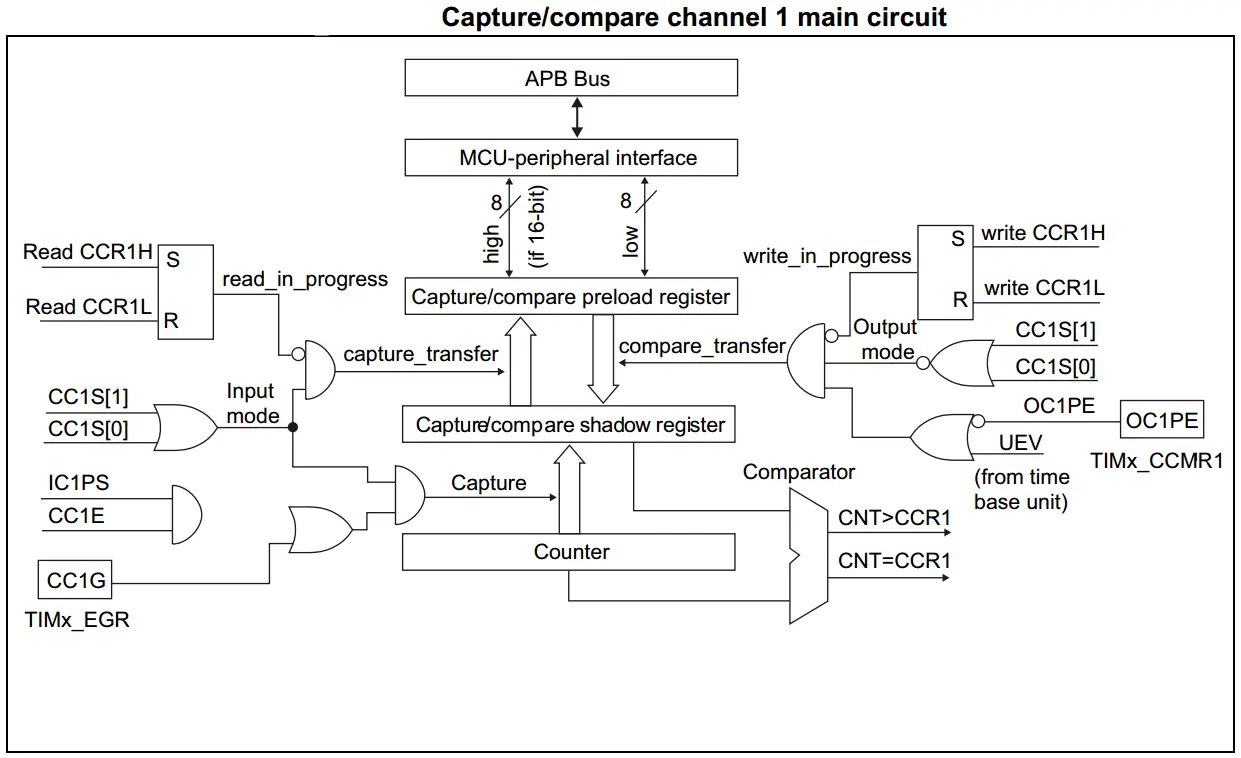
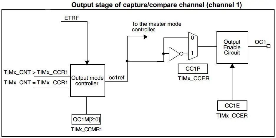
Each Capture/Compare channel is built around a capture/compare register (including a shadow register), an input stage for capture (with a digital filter, multiplexing, and Prescaler) and an output stage (with comparator and output control). The output stage generates an intermediate waveform which is then used for reference: OCxRef (active high). The polarity acts at the end of the chain.
And here is a diagram for the capture/compare channel 1 Full Circuitry
And here is a diagram for the output stage that driver the OCx pins
A single STM32 timer usually has multiple channels (4, 6, or whatever is found in the datasheet). Therefore, using a single timer you can independently generate multiple PWM signals with different duty cycles of course, but they'll share the same timing (same frequency), and all of them will be in sync. We'll do this in the 2nd LAB in this tutorial after we set up a single PWM channel and get everything up and running.
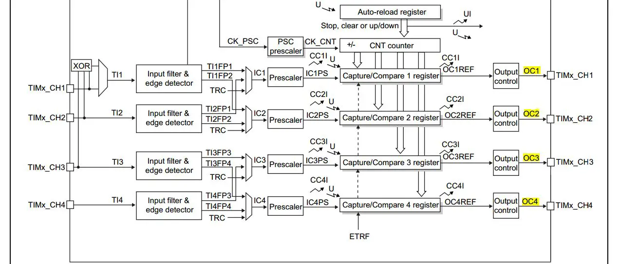
Here is a snapshot of the general-purpose Timer2 diagram, which highlights the presence of multiple output compare channels and output drivers.
STM32 Timers In PWM Mode
Pulse width modulation mode allows for generating a signal with a frequency determined by the value of the TIMx_ARR register and a duty cycle determined by the value of the TIMx_CCRx register. The PWM mode can be selected independently on each channel (one PWM per OCx output) by writing 110 (PWM mode 1) or ‘111 (PWM mode 2) in the OCxM bits in the TIMx_CCMRx register.
The user must enable the corresponding preload register by setting the OCxPE bit in the TIMx_CCMRx register, and eventually the auto-reload preload register by setting the ARPE bit in the TIMx_CR1 register.
OCx polarity is software programmable using the CCxP bit in the TIMx_CCER register. It can be programmed as active high or active low. For applications where you need to generate complementary PWM signals, this option will be suitable for you.
In PWM mode (1 or 2), TIMx_CNT and TIMx_CCRx are always compared to determine whether TIMx_CCRx ≤ TIMx_CNT or TIMx_CNT ≤ TIMx_CCRx (depending on the direction of the counter). The timer is able to generate PWM in edge-aligned mode or center-aligned mode depending on the CMS bits in the TIMx_CR1 register.
Note That PWM signals have a lot of properties that we need to control in various applications. The first of which is the frequency of the signal. And secondly, and probably the most important one, is the duty cycle. Third, is the PWM resolution. And much more to be discussed in later tutorials, we'll get into those 3 properties in the next sections below.
STM32 PWM Frequency
In various applications, you'll be in need to generate a PWM signal with a specific frequency. In servo motor control, LED drivers, motor drivers, and many more situations where you'll be in need to set your desired frequency for the output PWM signal.
The PWM period (1/FPWM) is defined by the following parameters: ARR value, the Prescaler value, and the internal clock itself which drives the timer module FCLK. The formula down below is to be used for calculating the FPWM for the output. You can set the clock you're using, the Prescaler, and solve for the ARR value in order to control the FPWM and get what you want.
STM32 PWM Duty Cycle
In normal settings, assuming you're using the timer module in PWM mode and generating a PWM signal in edge-aligned mode with up-counting configuration. The duty cycle percentage is controlled by changing the value of the CCRx register. And the duty cycle equals (CCRx/ARR) [%].
STM32 PWM Resolution
One of the most important properties of a PWM signal is the resolution. It's the number of discrete duty cycle levels that you can set it to. This number determines how many steps the duty cycle can take until it reaches the maximum value. So, the step size or the number of duty cycle steps can tell how fine can you change the duty cycle in order to achieve a certain percentage. This can be extremely important in some audio applications, motor control, or even light control systems.
This is the STM32 PWM resolution formula that can be used to calculate the resolution of the PWM signal at a specific frequency or even the opposite. If you're willing to get a 10-Bit resolution PWM signal, what should the frequency be in order to achieve this? And so on..
In other situations, you'll need to adjust the ARR value. Therefore, you'll need to know the relationship between it and the PWM resolution. This is not a new formula, it's derived from the first one and the FPWM equation that you've seen earlier in this tutorial. We'll need it in later tutorials to design our Motor driver library and some other applications.
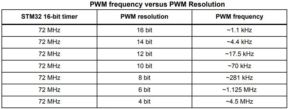
Check this table which shows you some example frequencies and the PWM resolution at each FPWM frequency.
STM32 PWM Different Modes
The PWM signal generation can be done in different modes, I'll be discussing two of them in this section. The edge-aligned and the center-aligned modes.
1- Edge-Aligned Mode
In the edge-aligned PWM mode there exist a couple of possible configurations:
- Up-Counting Configuration
- Down-Counting Configuration
In the following example, we consider PWM mode 1. The reference PWM signal OCxREF is high as long as TIMx_CNT <TIMx_CCRx else it becomes low. If the compare value in TIMx_CCRx is greater than the auto-reload value (in TIMx_ARR) then OCxREF is held at ‘1. If the compare value is 0 then OCxREF is held at ‘0.

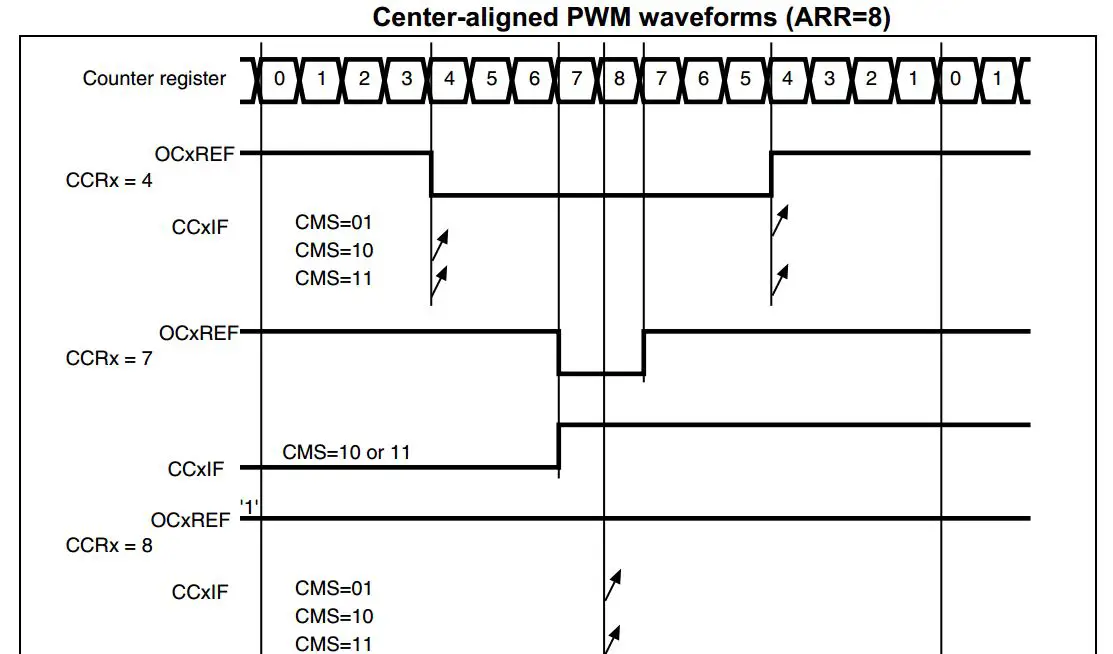
2- Center-Aligned Mode
The compare flag is set when the counter counts up when it counts down or both when it counts up and down depending on the CMS bits configuration. The direction bit (DIR) in the TIMx_CR1 register is updated by hardware and must not be changed by software.
The diagram below shows some center-aligned PWM waveforms in an example where: TIMx_ARR=8, PWM mode is the PWM mode 1.
STM32 PWM HAL Functions
The STM32 PWM HAL functions that you'll need to use is the HAL_TIM_PWM_Start() and HAL_TIM_PWM_Stop() functions. These are used to enable or disable the PWM channel output signal. You just need to configure the PWM output channel properly at first using CubeMX as we'll see in the example hereafter.
Both functions take two parameters only (the timer module handle, and the PWM channel number). Here is an example call to the HAL_TIM_PWM_Start() function to enable the PWM_CH1 in hardware Timer2 peripheral.
HAL_TIM_PWM_Start(&htim2, TIM_CHANNEL_1);
To change the duty cycle of the PWM signal, you only need to write the value to the corresponding CCR register. Let's consider the same example of PWM_CH1 in hardware Timer2 which has an ARR register value of 65535. Let's say we'd like to set this channel's PWM output duty cycle to 25%. Here is how to do it in code.
DutyCycle = CCR/ARR
0.25 = CCR / 65535
The value we need to write to the CCR register to set the duty cycle to 25% is, therefore, 16383. So, we can set the PWM's duty cycle in code as shown below:
TIM2->CCR1 = 16383;
You can change the line above TIMx->CCRy to match the numbers of the hardware timer you're using (x) and the PWM output channel (y) and you're good to go.
STM32 PWM Output Example LED Dimmer
In this STM32 PWM example, we'll do the following:
- Set up timer 2 to operate in PWM mode with the internal clock. And enable CH1 to be the PWM output channel.
- Set the ARR value to the maximum 65535 for example, so the frequency should be 1098Hz
- Control the duty cycle by writing to the CCR1 register
- Make Duty Cycle sweep from 0% up to 100% back and forth
STM32 PWM Example LED Dimmer
In this LAB, our goal is to build a system that sweeps the duty cycle of the PWM channel1 from 0 up to 100% back and forth. So that the LED brightness follows the same pattern. The auto-reload register will be set to a maximum value which is 65535, for no particular reason.
But you should know that the output FPWM frequency is expected to be 1098.6Hz from the equation we've seen earlier. And the PWM resolution is estimated to be 16-Bit which is the maximum possible value for this module.
STM32 PWM CubeMX HAL Configuration Steps
#1
Open CubeMX, Create a New Project, Choose The Target MCU & Double-Click Its Name
#2
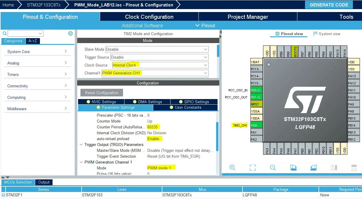
Configure Timer2 Peripheral To Operate In PWM Mode With CH1 Output
#3
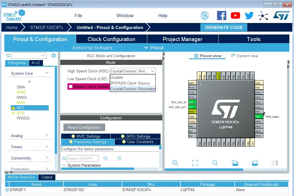
Set The RCC External Clock Source
#4
Go To The Clock Configuration, Set The System Clock to 72MHz

#5
Name & Generate The Project Initialization Code For CubeIDE or The IDE You're Using
STM32 PWM Example Code
#include "main.h"

TIM_HandleTypeDef htim2;

void SystemClock_Config(void);
static void MX_GPIO_Init(void);
static void MX_TIM2_Init(void);

int main(void)
{
    int32_t CH1_DC = 0;

    HAL_Init();
    SystemClock_Config();
    MX_GPIO_Init();
    MX_TIM2_Init();
    HAL_TIM_PWM_Start(&htim2, TIM_CHANNEL_1);
    while (1)
    {
    	while(CH1_DC < 65535)
    	{
    	    TIM2->CCR1 = CH1_DC;
    	    CH1_DC += 70;
    	    HAL_Delay(1);
    	}
    	while(CH1_DC > 0)
    	{
    	    TIM2->CCR1 = CH1_DC;
    	    CH1_DC -= 70;
    	    HAL_Delay(1);
    	}
    }
}
Testing Results
Note that the frequency is exactly 1098.6Hz!
The resulting PWM LED Dimmer
Required Parts For STM32 Examples
All the example Code/LABs/Projects in this STM32 Series of Tutorials are done using the Dev boards & Electronic Parts Below:
| QTY. | Component Name | Amazon.com | AliExpress | eBay |
| 1 | STM32-F103 BluePill Board (ARM Cortex-M3 @ 72MHz) | Amazon | AliExpress | eBay |
| 1 | Nucleo-L432KC (ARM Cortex-M4 @ 80MHz) | Amazon | AliExpress | eBay |
| 1 | ST-Link V2 Debugger | Amazon | AliExpress | eBay |
| 2 | BreadBoard | Amazon | AliExpress | eBay |
| 1 | LEDs Kit | Amazon & Amazon | AliExpress | eBay |
| 1 | Resistors Kit | Amazon & Amazon | AliExpress | eBay |
| 1 | Capacitors Kit | Amazon & Amazon | AliExpress & AliExpress | eBay & eBay |
| 1 | Jumper Wires Pack | Amazon & Amazon | AliExpress & AliExpress | eBay & eBay |
| 1 | Push Buttons | Amazon & Amazon | AliExpress | eBay |
| 1 | Potentiometers | Amazon | AliExpress | eBay |
| 1 | Micro USB Cable | Amazon | AliExpress | eBay |
★ Check The Links Below For The Full Course Kit List & LAB Test Equipment Required For Debugging ★
Download Attachments
You can download all attachment files for this Article/Tutorial (project files, schematics, code, etc..) using the link below. Please consider supporting my work through the various support options listed in the link down below. Every small donation helps to keep this website up and running and ultimately supports our community.
STM32 PWM Wrap-Up
To conclude this tutorial, we'd like to highlight the fact that you can easily generate PWM signals with STM32 microcontrollers using the hardware timers in PWM mode. Which generates a PWM signal and we can control its frequency & duty cycle. This tutorial is a fundamental part of our STM32 Series of Tutorials because we’ll use it in so many tutorials and projects hereafter. So make sure, you’ve learned all the concepts and implemented the practice examples.
This was the 1st tutorial in the STM32 PWM Tutorial Series which you can navigate through using the links in the table below.
 Example Code Mode1-2-3")

 Example Code")

 + Example Code")
")
 - Stop PWM Safely")
If you're just getting started with STM32, you need to check out the STM32 Getting Started Tutorial here.
And follow this STM32 Series of Tutorials to learn more about STM32 Microcontrollers Programming.
My project isnt recognising those 3 rows
SystemClock_Config();
MX_GPIO_Init();
MX_TIM2_Init();
Where are they and how are they generated?
Those functions are generated by CubeMX and you can find the definition of each function in the main.c file
can you give wiring this experiment?
thank you
Hi I want to to learn STM32CUBEIDE code for a 3 phase bldc motor to control speed with pot cw ccw start stop can you help coding min max speed