In this tutorial, we’ll discuss the STM32 ADC Timer Trigger & External Trigger Sources For ADC channels’ conversion starting instead of the software-triggered mode that we’ve discussed in previous tutorials. Using the timer as a trigger source for the ADC allows for periodic ADC conversions to achieve whatever ADC sampling rate is required by your application.
The practical example we’ll implement in this tutorial is an STM32 LED dimmer using a potentiometer on an analog input pin and a PWM output to control the brightness of the LED. We’ll read the analog input regular channel in single-conversion mode using the ADC interrupt & we’ll use a Timer TRGO event to trigger the ADC every 20ms (to achieve a 50Hz sampling rate). Without further ado, let’s get right into it!
Table of Contents
- STM32 ADC Timer Trigger & External Trigger Sources
- STM32 ADC Timer Trigger Example Overview
- STM32 ADC Timer Trigger Example
- Wrap Up
STM32 ADC Timer Trigger & External Trigger Sources
The default option to trigger the STM32 ADC to start the conversion process is the Software Trigger source. Therefore, we had to manually call the HAL_ADC_Start() function whenever we wanted to start a new ADC conversion. However, the ADC can also be automatically triggered by internal or external trigger sources in the STM32 microcontroller itself.
This can be really useful to set the ADC conversion to occur periodically using a timer trigger to achieve a desired ADC sampling rate. Or to trigger the ADC conversion to start at a specific time relative to some output PWM signal (a very important feature for advanced measurement systems).
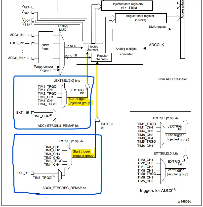
Below is the ADC block diagram as found in the datasheet for STM32F103xx target microcontrollers. It shows us that both the ADC regular channels and the injected channels can be triggered by internal hardware sources or external trigger pins.
1. STM32 ADC Timer Trigger Sources
As stated earlier, the timer trigger source can be very helpful to automatically set the ADC sampling rate with very little CPU intervention. The timer’s trigger output (TRGO) event can be configured to any one of the options shown below.
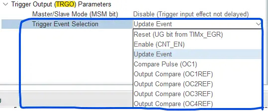
2. STM32 ADC External Trigger Sources
The external EXTI_x pins can be used to trigger the ADC to start the conversion on the rising or falling edge of the associated external GPIO pin. This feature can be really useful if we’d like to sync multiple ADCs in different microcontrollers so they start the conversion process at the exact same time. There are so many other applications for this feature as we’ll see in future STM32 projects.
Consider using DMA (Direct Memory Access) for efficient data transfer from the ADC data buffer register to memory. This can reduce the CPU overhead and ensure a smoother flow of data, especially in applications where a high ADC sampling rate is needed.
STM32 ADC Timer Trigger Example Overview
In this example project, we’ll create an STM32 LED Dimmer using ADC & PWM to read an analog input of a potentiometer to control the brightness of a PWM output going to an LED. This demo will run the STM32 ADC in Regular Channel Single-Conversion Timer-Triggered Mode With ADC Interrupt Enabled. In the ADC ISR, we’ll read the conversion result into a global buffer and toggle a GPIO pin to measure the ADC sampling rate.
Example Project Steps Summary:
- Set up a new project with a system clock @ 72MHz
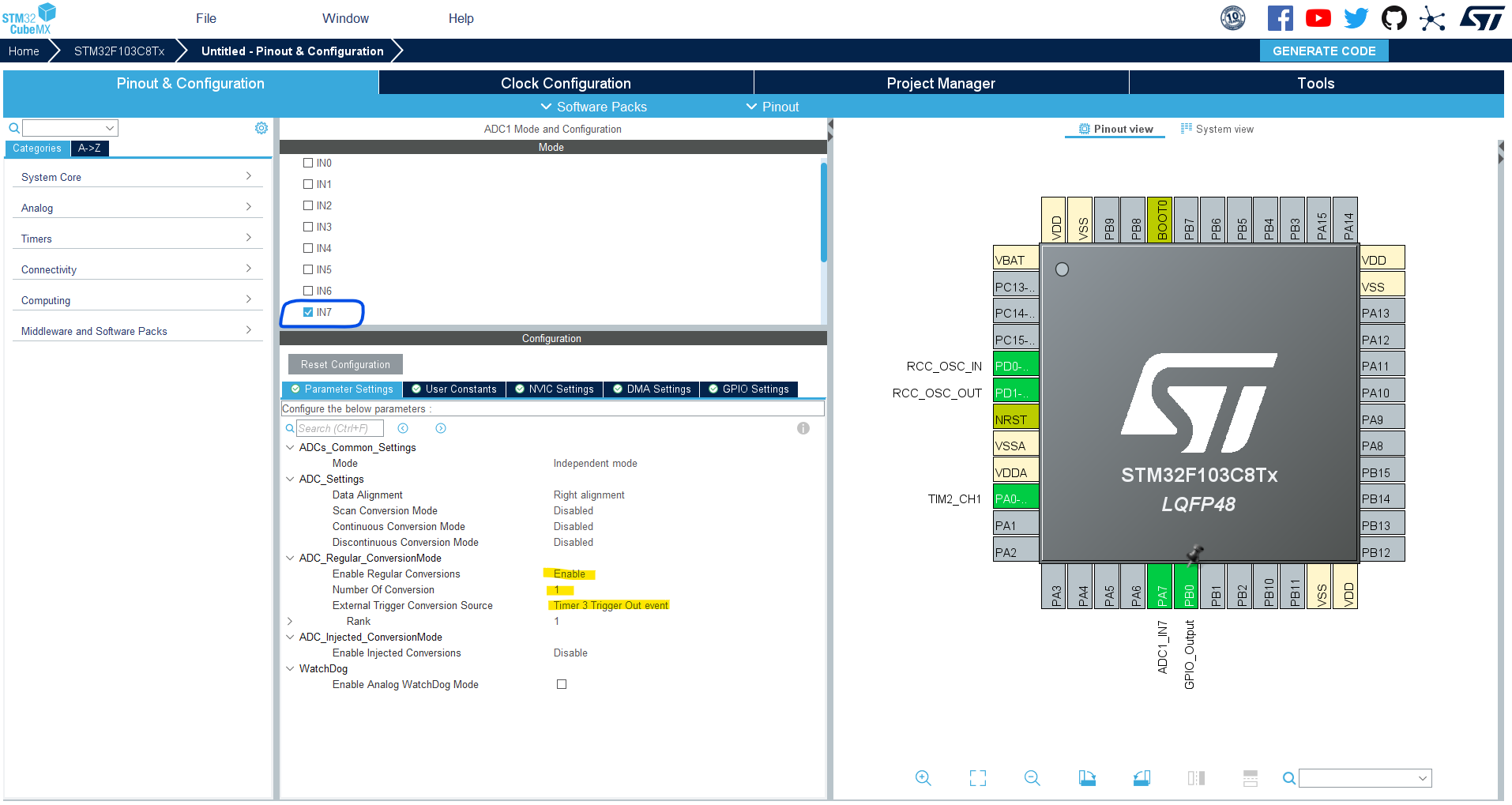
- Set up an Analog input pin (Channel 7) in Regular Single-Conversion Mode With Timer3 TRGO event as a trigger source
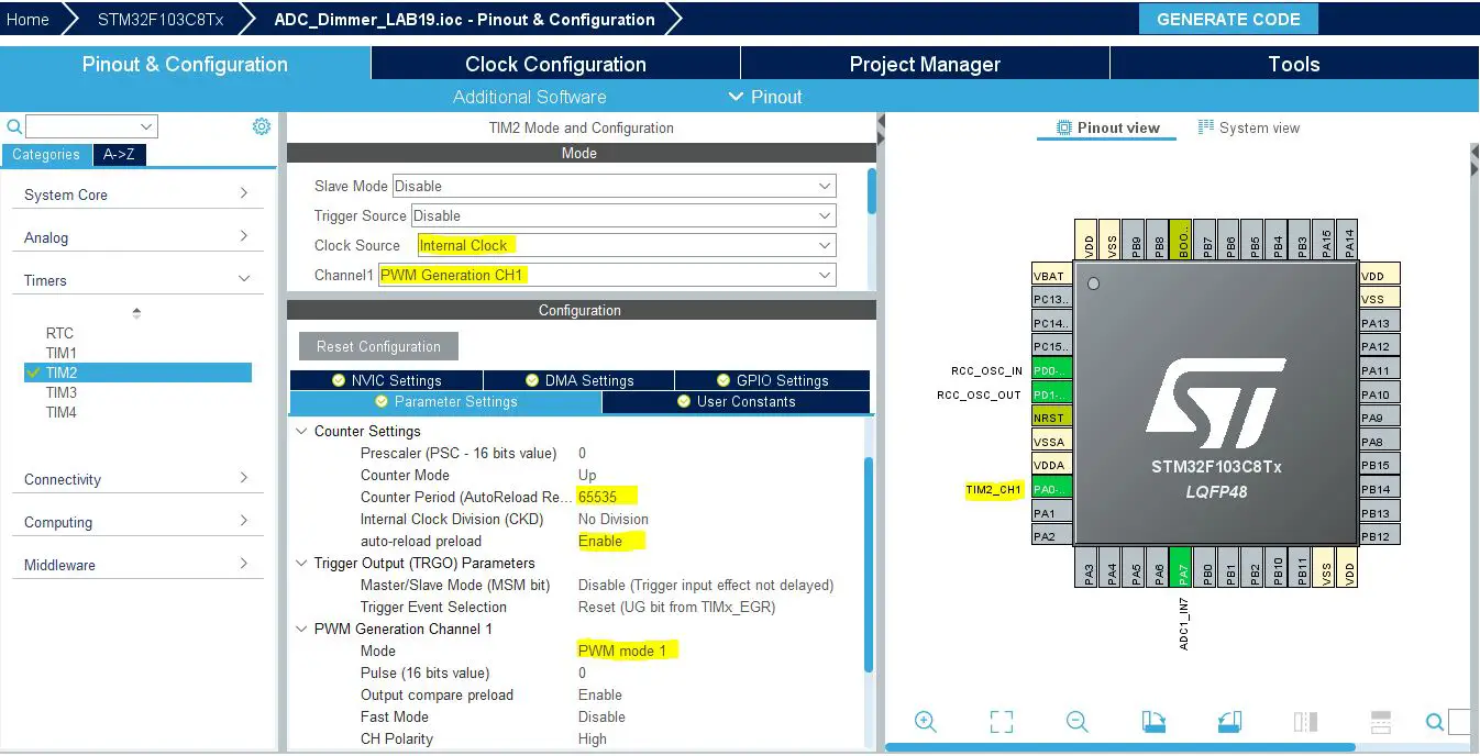
- Set up Timer2 in PWM mode with output on channel 1 (The LED pin)
- Set up Timer3 to generate an update event as a TRGO @ 20ms (50Hz rate) (so the ADC sampling rate will also be 50Hz)
- Set up a GPIO pin as an output pin, so we can toggle it in the ADC’s ISR to measure the ADC sampling rate
STM32 ADC Timer Trigger Example
In this example project, we’ll set up an ADC input regular channel (CH7) in single-conversion mode to be triggered by Timer3 which generates a TRGO event @ 20ms time intervals, so the ADC will sample the input channel @ 50Hz sampling rate. The ADC conversion completion will trigger an ADC interrupt event. In the ADC ISR handler, we’ll read and store the ADC reading into a global buffer variable and toggle a GPIO pin to measure the sampling rate using a DSO (digital storage oscilloscope).
We’ll also set up Timer2 in PWM mode to generate a PWM signal to control an LED’s brightness using the reading of the ADC input channel (from a potentiometer). The Timer3 will continuously trigger the ADC regular channel to start the conversion every 20ms, so we don’t need to continuously start the ADC manually in the main while(1) loop.
And now, let’s build this system step-by-step
Step #1
Open STM32CubeMX, create a new project, and select the target microcontroller.
Step #2
Configure The ADC1 Peripheral, Enable the regular Channel-7, and select the Timer3 TRGO event as a trigger source. In the NVIC tab, enable the ADC1 global interrupt.
Step #3
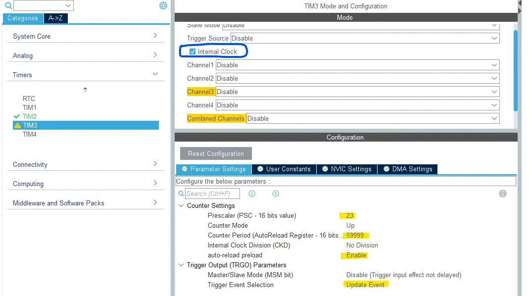
For Timer3, we need to enable the internal clock for the timer (72MHz). Next, we need to set it in such a way that it generates an update event every 20ms to achieve the desired 50Hz ADC sampling rate. For this, you can use our STM32 Timer Calculator to get the required values for the Prescaler (PSC) and Auto-Reload Register (ARR) in order to achieve the 20ms update time interval. You’ll get PSC=23 & ARR=59999 from the calculator.
Finally, choose the TRGO event to be “Update Event“. And that’s all about it.
Step #4
Configure Timer2 To Operate In PWM Mode With Output On CH1 (for the LED brightness control).
Step #5
Go to the RCC clock configuration page and enable the HSE external crystal oscillator input.
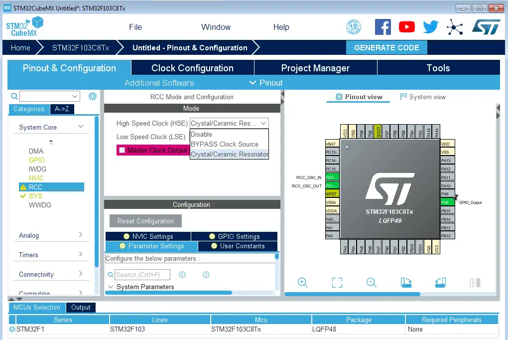
Step #6
Go to the clock configurations page, and select the HSE as a clock source, PLL output, and type in 72MHz for the desired output system frequency. Hit the “ Enter” key, and let the application solve for the required PLL dividers/multipliers to achieve the desired clock rate.
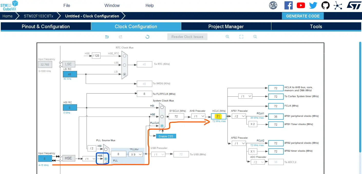
Step #7
Name & Generate The Project Initialization Code For CubeIDE or The IDE You’re Using.
STM32 ADC Timer Trigger Example Code
Here is The Application Code For This LAB (main.c)
|
1 2 3 4 5 6 7 8 9 10 11 12 13 14 15 16 17 18 19 20 21 22 23 24 25 26 27 28 29 30 31 32 33 34 35 36 37 38 39 40 41 |
/* * LAB Name: STM32 ADC Timer Trigger Example (Regular Channel, Single-Conv, Interrupt) * Author: Khaled Magdy * For More Info Visit: www.DeepBlueMbedded.com */ #include "main.h" ADC_HandleTypeDef hadc1; TIM_HandleTypeDef htim2; TIM_HandleTypeDef htim3; uint16_t AD_RES = 0; void SystemClock_Config(void); static void MX_GPIO_Init(void); static void MX_ADC1_Init(void); static void MX_TIM2_Init(void); static void MX_TIM3_Init(void); int main(void) { HAL_Init(); SystemClock_Config(); MX_GPIO_Init(); MX_ADC1_Init(); MX_TIM2_Init(); MX_TIM3_Init(); HAL_TIM_PWM_Start(&htim2, TIM_CHANNEL_1); // Start PWM: TIM2 (CH1) HAL_TIM_Base_Start(&htim3); // Start Timer3 (Trigger Source For ADC1) HAL_ADC_Start_IT(&hadc1); // Start ADC Conversion while (1) { TIM2->CCR1 = (AD_RES<<4); // Update The PWM Duty Cycle With Latest ADC Conversion Result } } void HAL_ADC_ConvCpltCallback(ADC_HandleTypeDef* hadc) { AD_RES = HAL_ADC_GetValue(&hadc1); // Read & Update The ADC Result HAL_GPIO_TogglePin(GPIOB, GPIO_PIN_0); // Toggle Interrupt Rate Indicator Pin } |
STM32 ADC Timer Trigger Code Explanation
We need to start the Timer3 module by calling the HAL_TIM_Base_Start(&htim3) function so it can trigger the ADC every 20ms. And we also need to start the ADC in interrupt mode at least once before the while(1) loop. Afterward, the ADC will be automatically triggered by the Timer3 module and we don’t need to call any function to start/trigger the ADC.
In the while(1) loop, we’ll continuously update the PWM output’s duty cycle with the latest value in the ADC_RES buffer.
|
1 |
TIM2->CCR1 = (AD_RES<<4); |
Finally, in the ADC interrupt handler (ISR), we’ll read and store the ADC conversion result into the global buffer variable and toggle the GPIO (B0) pin to measure the ADC sampling rate (frequency).
Wiring
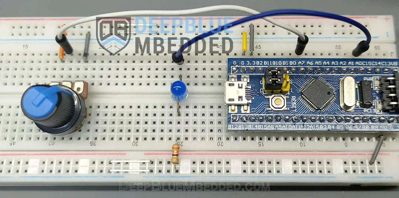
STM32 ADC Timer Trigger Example Testing
Yellow Trace: GPIO (B0) showing ADC sampling period of 20ms (50Hz), it’s double the measured signal’s frequency because we’re toggling the pin once every ADC conversion interrupt so the signal’s period = 2 ADC conversion cycles.
Blue Trace: the LED PWM output signal.
Required Parts For STM32 Examples
All the example Code/LABs/Projects in this STM32 Series of Tutorials are done using the Dev boards & Electronic Parts Below:
| QTY. | Component Name | Amazon.com | AliExpress | eBay |
| 1 | STM32-F103 BluePill Board (ARM Cortex-M3 @ 72MHz) | Amazon | AliExpress | eBay |
| 1 | Nucleo-L432KC (ARM Cortex-M4 @ 80MHz) | Amazon | AliExpress | eBay |
| 1 | ST-Link V2 Debugger | Amazon | AliExpress | eBay |
| 2 | BreadBoard | Amazon | AliExpress | eBay |
| 1 | LEDs Kit | Amazon & Amazon | AliExpress | eBay |
| 1 | Resistors Kit | Amazon & Amazon | AliExpress | eBay |
| 1 | Capacitors Kit | Amazon & Amazon | AliExpress & AliExpress | eBay & eBay |
| 1 | Jumper Wires Pack | Amazon & Amazon | AliExpress & AliExpress | eBay & eBay |
| 1 | Push Buttons | Amazon & Amazon | AliExpress | eBay |
| 1 | Potentiometers | Amazon | AliExpress | eBay |
| 1 | Micro USB Cable | Amazon | AliExpress | eBay |
★ Check The Links Below For The Full Course Kit List & LAB Test Equipment Required For Debugging ★
Download Attachments
You can download all attachment files for this Article/Tutorial (project files, schematics, code, etc..) using the link below. Please consider supporting our work through the various support options listed in the link down below. Every small donation helps to keep this website up and running and ultimately supports the whole community.
Wrap Up
In conclusion, we’ve explored how to set up the STM32 ADC to be triggered by a hardware timer module to achieve periodic ADC conversions without CPU intervention. Using this technique any ADC sampling rate can be easily achieved. This works for regular and/or injected ADC channels in any mode you’d like to use. You can also use interrupts or DMA to handle the ADC conversion completion events. For high ADC sampling rate applications, the DMA will be a much better choice than the interrupt-based reading scheme.
You can build on top of the examples provided in this tutorial and/or explore the other parts of the STM32 ADC tutorials series for more information about the other STM32 ADC operating modes and conversion schemes.
