In this tutorial, we’ll discuss the STM32 UART DMA Mode (Receive/Transmit). Using the STM32 UART DMA mode is a significantly more efficient way of transmitting/receiving data over UART while keeping the CPU not loaded most of the time. We’ll implement an STM32 UART DMA Rx/Tx Example project to practice what we’ll learn in this tutorial. Without further ado, let’s get right into it!
Table of Contents
- STM32 UART Receive/Transmit (Rx/Tx)
- STM32 UART DMA Receive (Rx) Example Overview
- STM32 UART DMA Rx/Tx (Receive/Transmit) Example
- Wrap Up
STM32 UART Receive/Transmit (Rx/Tx)
This tutorial is intended to be an example application for STM32 UART DMA Rx/Tx operations. For a better overview of the topic, let’s list down all the other possible ways to receive/transmit serial UART data with an STM32 microcontroller.
1. STM32 UART Polling Method
The polling method is essentially a blocking function being called from the main routine and it does block the CPU so it can’t proceed in the main task execution until a certain amount of UART data bytes are received. After receiving the required amount of data, the function ends and the CPU continues the main code execution.
Otherwise, and if the UART peripheral for some reason didn’t receive the expected amount of data, the function will keep blocking the CPU for a certain amount of time “time-out” after which it gets terminated and gives back control to the CPU to resume the main code.
This function for example
HAL_UART_Receive(&huart1, UART1_rxBuffer, 12, 5000);
Receives 12 bytes to the buffer. if it does that in 100uSec, it’s ok and the CPU will resume main code execution. If it doesn’t receive that amount of data, the CPU will be kept blocked waiting for 5sec until this function returns to the main context. Obviously, it’s not the most efficient way to receive serial data despite the fact that it does actually work.
The same goes for the transmit function as well.
HAL_UART_Transmit(&huart1, UART1_txBuffer, sizeof(UART1_txBuffer), 100);
2. STM32 UART Interrupt Method
Using interrupt signals is a convenient way to achieve serial UART data reception. The CPU initializes the UART receive hardware so that it fires an interrupt signal whenever a new byte of data is received. And in the ISR code, we save the received data in a buffer for further processing.
This way of handling the UART data reception is a non-blocking way. As the CPU initiates the receiving process, it resumes executing the main code. Until an interrupt is received, then it freezes the main context and switches to the ISR handler to save the received byte to a buffer, switches back to the main context, and resumes the main code.
HAL_UART_Receive_IT(&huart1, UART1_rxBuffer, 12);
The above function initializes the UART receive process in interrupt mode (non-blocking) and upon completion, a callback function is called to notify the application and the processor knows that the received data buffer is now ready.
This method is a non-blocking one, yet very efficient. However, if you’re receiving a continuous stream of serial data, an insane number of interrupts per second will have to be handled by the CPU which is a huge load and a waste of time for it.
In this situation, even the interrupt method will be inefficient and unnecessarily load the CPU and consume too much of the CPU time. In the worst scenario, there might be some data packets lost or dropped in the way. Now, it comes the time to use the DMA method.
3. STM32 UART DMA Method
Using the DMA unit in order to direct the received serial UART data from the UART peripheral directly to the memory is considered to be the most efficient way to do such a task. It requires no CPU intervention at all, you’ll have only to set it up and execute the main application code. The DMA will notify back the CPU upon reception completion and the received data buffer will be in the pre-programmed location.
The DMA can prioritize the channels, decide on the data width, and also the amount of data to be transferred up to 65536 bytes. Which is amazing in fact, and all you’ve got to do is to initialize it like this.
HAL_UART_Receive_DMA(&huart1, UART1_rxBuffer, 12);
STM32 UART DMA Receive (Rx) Example Overview
In this example project, we’ll receive a fixed length of data bytes from the PC terminal and echo back the received data buffer. So in the testing, we’ll expect to see back whatever data we send through the terminal.
Example Project Steps Summary:
- Set up a new project, configure the RCC, clock tree, and enable SWD (serial wire debug)
- Set up 1x UART channel to be used for receiving/transmitting serial data from/to PC
- Enable 1x DMA channel for the UART Rx peripheral to handle data reception
STM32 UART DMA Rx/Tx (Receive/Transmit) Example
Let’s now build this system step-by-step
Step #1
Open STM32CubeMX, create a new project, and select the target microcontroller.
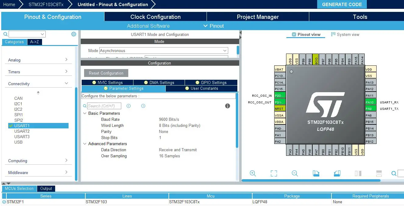
Step #2
Enable UART1 and leave the default configurations as is without a change (9600 baud rate).
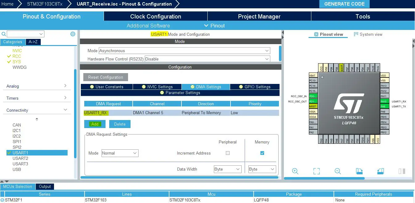
Add A DMA Channel For UART RX From The DMA Tab
Step #3
Go to the RCC clock configuration page and enable the HSE external crystal oscillator input.

Step #4
Go to the clock configurations page, and select the HSE as a clock source, PLL output, and type in 72MHz for the desired output system frequency. Hit the “ Enter” key, and let the application solve for the required PLL dividers/multipliers to achieve the desired clock rate.

Step #5
Name & Generate The Project Initialization Code For CubeIDE or The IDE You’re Using.
STM32 UART DMA Example Code
Here is The Application Code For This LAB (main.c)
|
1 2 3 4 5 6 7 8 9 10 11 12 13 14 15 16 17 18 19 20 21 22 23 24 25 26 27 28 29 30 31 32 33 34 35 36 37 38 39 |
/* * LAB Name: STM32 UART DMA Example * Author: Khaled Magdy * For More Info Visit: www.DeepBlueMbedded.com */ #include "main.h" uint8_t UART1_rxBuffer[12] = {0}; UART_HandleTypeDef huart1; DMA_HandleTypeDef hdma_usart1_rx; void SystemClock_Config(void); static void MX_GPIO_Init(void); static void MX_DMA_Init(void); static void MX_USART1_UART_Init(void); int main(void) { HAL_Init(); SystemClock_Config(); MX_GPIO_Init(); MX_DMA_Init(); MX_USART1_UART_Init(); HAL_UART_Receive_DMA (&huart1, UART1_rxBuffer, 12); while (1) { } } void HAL_UART_RxCpltCallback(UART_HandleTypeDef *huart) { HAL_UART_Transmit(&huart1, UART1_rxBuffer, 12, 100); HAL_UART_Receive_DMA(&huart1, UART1_rxBuffer, 12); } |
Code Explanation
In the main() function, we Call the HAL_UART_Receive_DMA to start DMA reception of UART data into the UART1_rxBuffer. The DMA will transfer every received character until the count reaches 12, and then it’ll fire the transfer completion interrupt.
The callback function HAL_UART_RxCpltCallback is called when the DMA transfer is complete.
- In this callback function, it transmits the received data back over UART using HAL_UART_Transmit.
- Then it sets up another DMA receive operation using HAL_UART_Receive_DMA to continuously receive UART data.
STM32 UART DMA Receive (Rx) Example Testing
This is the testing result on the serial terminal. The message I’ve sent from the PC to the STM32 microcontroller has been echoed back to the terminal. Every 12 characters sent from the PC to the STM32 microcontroller are received into the buffer array and sent back (transmitted) over UART to the PC.

This example project divides the incoming data into 12-byte chunks, each of which is handled in the DMA transfer completion interrupt. You can, however, increase or decrease the buffer length as you want.
However, the most common question at this point is what if I don’t know the incoming data length, how can we handle incoming UART data of unknown length? That’s what we’ll discuss in the next tutorial of this mini-series, so check out the next part of this tutorial series after the wrap-up section below.
Required Parts For STM32 Examples
All the example Code/LABs/Projects in this STM32 Series of Tutorials are done using the Dev boards & Electronic Parts Below:
| QTY. | Component Name | Amazon.com | AliExpress | eBay |
| 1 | STM32-F103 BluePill Board (ARM Cortex-M3 @ 72MHz) | Amazon | AliExpress | eBay |
| 1 | Nucleo-L432KC (ARM Cortex-M4 @ 80MHz) | Amazon | AliExpress | eBay |
| 1 | ST-Link V2 Debugger | Amazon | AliExpress | eBay |
| 2 | BreadBoard | Amazon | AliExpress | eBay |
| 1 | LEDs Kit | Amazon & Amazon | AliExpress | eBay |
| 1 | Resistors Kit | Amazon & Amazon | AliExpress | eBay |
| 1 | Capacitors Kit | Amazon & Amazon | AliExpress & AliExpress | eBay & eBay |
| 1 | Jumper Wires Pack | Amazon & Amazon | AliExpress & AliExpress | eBay & eBay |
| 1 | Push Buttons | Amazon & Amazon | AliExpress | eBay |
| 1 | Potentiometers | Amazon | AliExpress | eBay |
| 1 | Micro USB Cable | Amazon | AliExpress | eBay |
★ Check The Links Below For The Full Course Kit List & LAB Test Equipment Required For Debugging ★
Download Attachments
You can download all attachment files for this Article/Tutorial (project files, schematics, code, etc..) using the link below. Please consider supporting our work through the various support options listed in the link down below. Every small donation helps to keep this website up and running and ultimately supports the whole community.
Wrap Up
In conclusion, we’ve explored how to set up the STM32 UART DMA channels for data reception or transmission. You can build on top of the examples provided in this tutorial and/or explore the other parts of this STM32 UART tutorial series linked below.

 Rx Tx Examples")


