In this tutorial, we’ll discuss the STM32 Analog Watchdog ADC Mode, how it works, and how to configure the STM32 ADC analog watchdog for a specific input channel. We’ll also discuss how the analog watchdog (AWD) interrupt is handled, and how you can use it to command the MCU to go in/out of sleep mode or do anything else based on that event.
The practical example we’ll implement in this tutorial will include a regular channel of ADC configured with the analog watchdog feature with AWD interrupt enabled. Without further ado, let’s get right into it!
Table of Contents
- STM32 Analog Watchdog ADC Mode
- STM32 ADC Analog Watchdog Example Project
- STM32 ADC Analog Watchdog Example
- Wrap Up
STM32 Analog Watchdog ADC Mode
The STM32 Analog Watchdog ADC Mode acts like a window comparator running in the background of the ADC operation. Its job is to check the voltage level of the AWD-enabled channels to make sure it’s within the “programmed” threshold levels. If the analog input voltage goes out of the configured voltage window, the AWD will fire an interrupt.

The high and low threshold voltage levels are shared between all channels that have AWD enabled. These values are globally configured for all channels with AWD, not on a per-channel basis. The analog watchdog feature, however, can be enabled for a single regular channel, single injected channel, all injected channels, all regular channels, or all ADC channels.
The analog watchdog interrupt is fired when the input voltage goes out of the guarded area levels and it’ll keep triggering as long as the voltage is still out of the configured threshold window. This can tremendously overload the CPU with an excessive number of interrupts/second if the input voltage stays out of bounds for some time.
STM32 ADC Analog Watchdog Example Project
In this example project, we’ll set up the STM32 ADC analog watchdog to monitor the voltage level on the regular channel (CH7) and make sure it stays within the following range: 1v-2v. When the analog input voltage goes out of this guarded voltage window, the AWD interrupt will fire and we’ll turn ON an indicator LED.
Example Project Steps Summary:
- Set up a new project with a system clock @ 72MHz
- Set up an Analog input pin (Channel 7) in Regular Continuous-Conversion Mode (for the potentiometer).
- Enable the analog watchdog (AWD) for CH7 with the following thresholds: 1v, 2v
- Set up a GPIO pin as an output pin for an LED, so we can turn it ON whenever an AWD interrupt is fired.
STM32 ADC Analog Watchdog Example
And now, let’s build this system step-by-step
Step #1
Open STM32CubeMX, create a new project, and select the target microcontroller.
Step #2
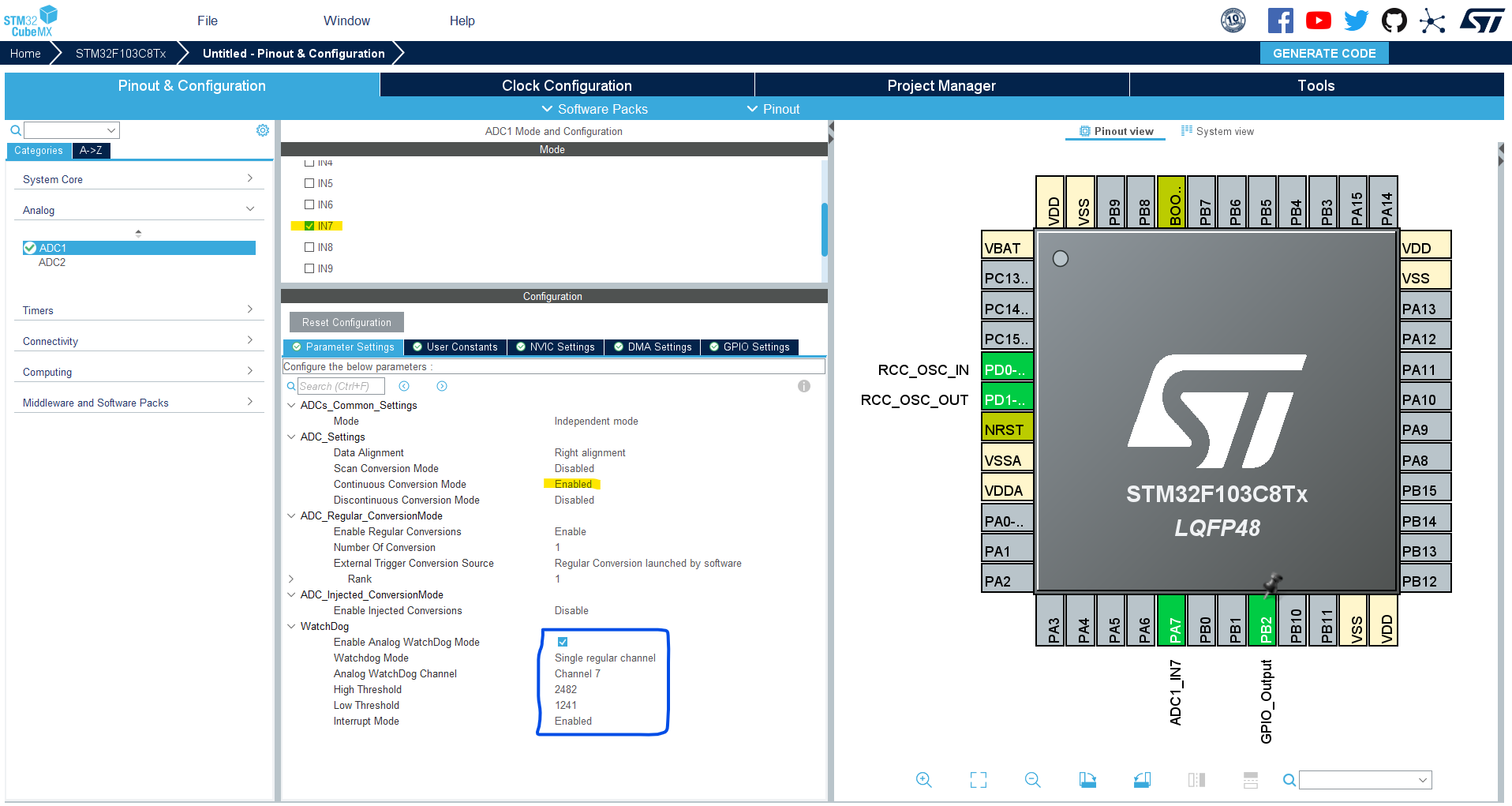
Configure The ADC1 Peripheral, Enable the regular Channel-7 in continuous conversion mode. Enable the ADC’s analog watchdog (AWD) for CH7, and give it the following thresholds: 1241 (1v) and 2482 (2v), and enable its interrupt. In the NVIC tab, enable the ADC1 global interrupt.
Set the GPIO B1 as an output pin (for the LED).
Step #3
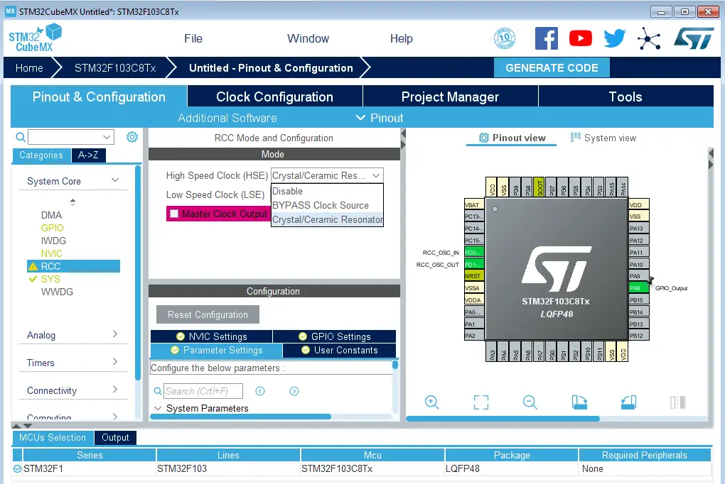
Go to the RCC clock configuration page and enable the HSE external crystal oscillator input.
Step #4
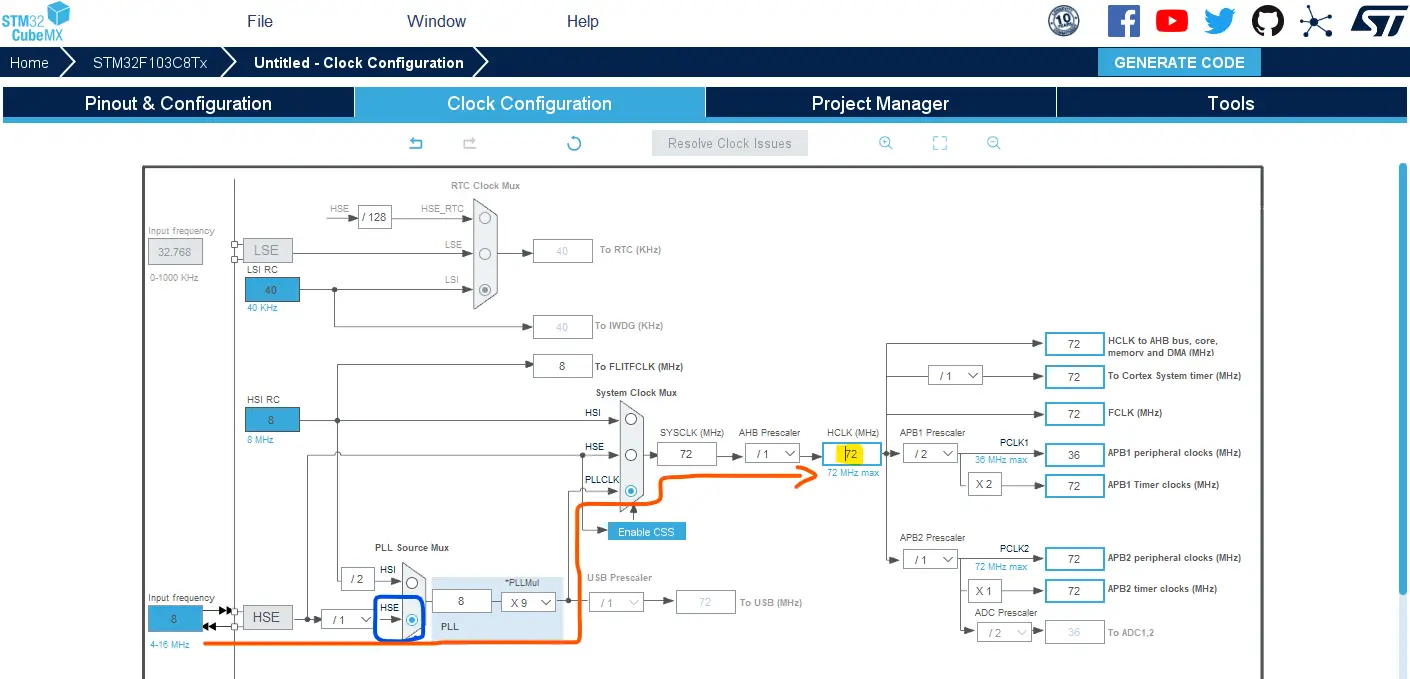
Go to the clock configurations page, select the HSE as a clock source, PLL output, and type in 72MHz for the desired output system frequency. Hit the “ Enter” key, and let the application solve for the required PLL dividers/multipliers to achieve the desired clock rate.
Step #5
Name & Generate The Project Initialization Code For CubeIDE or The IDE You’re Using.
STM32 Analog Watchdog ADC Example Code
Here is The Application Code For This LAB (main.c)
|
1 2 3 4 5 6 7 8 9 10 11 12 13 14 15 16 17 18 19 20 21 22 23 24 25 26 27 28 29 30 31 |
/* * LAB Name: STM32 ADC Analog Watchdog Example * Author: Khaled Magdy * For More Info Visit: www.DeepBlueMbedded.com */ #include "main.h" ADC_HandleTypeDef hadc1; void SystemClock_Config(void); static void MX_GPIO_Init(void); static void MX_ADC1_Init(void); int main(void) { HAL_Init(); SystemClock_Config(); MX_GPIO_Init(); MX_ADC1_Init(); HAL_ADC_Start(&hadc1); // Start ADC Conversion (Regular Channel, Continuous Mode, Polling) while (1) { HAL_GPIO_WritePin(GPIOB, GPIO_PIN_1, GPIO_PIN_RESET); } } void HAL_ADC_LevelOutOfWindowCallback(ADC_HandleTypeDef* hadc) { HAL_GPIO_WritePin(GPIOB, GPIO_PIN_1, GPIO_PIN_SET); } |
Analog Watchdog Code Explanation
We first start the ADC1 which has only one channel (CH7) configured in continuous mode, so it’ll keep auto-triggering itself and we don’t need to manually start the ADC repeatedly anymore.
In the AWD’s ISR handler ( HAL_ADC_LevelOutOfWindowCallback ), we drive the indicator LED’s pin HIGH. And in the main while(1) loop, we drive the pin back to LOW. The HAL_ADC_LevelOutOfWindowCallback() function resets the interrupt flag of the AWD automatically and we don’t need to reset it manually.
STM32 Analog Watchdog ADC Example Testing
Blue Trace: the analog input voltage going to the ADC CH7 channel. The horizontal cursors are set at (1v, 2v) respectively to show you the voltage window so we can easily identify if the system is behaving as intended or not.
Yellow Trace: GPIO (B1) showing the indicator pin state and how it behaves when the analog voltage goes out of bounds.
The behavior captured on the oscilloscope in this project’s demo shows that the analog watchdog (AWD) interrupt will keep firing as long as the input voltage stays out of bounds (thresholds). That’s why the LED was toggling at an extremely high frequency (285kHz) which can be a very serious issue for real-time systems.
We can, however, raise a global flag variable inside the ISR to keep it as short as possible and process the needed logic (go in/out of sleep mode, take an action, or do anything) somewhere else at a lower rate depending on how fast your system needs to respond to that AWD event.
Polling for the AWD event can also be an option for some systems under certain circumstances. For this, you need to call the HAL_ADC_PollForEvent() function.
Required Parts For STM32 Examples
All the example Code/LABs/Projects in this STM32 Series of Tutorials are done using the Dev boards & Electronic Parts Below:
| QTY. | Component Name | Amazon.com | AliExpress | eBay |
| 1 | STM32-F103 BluePill Board (ARM Cortex-M3 @ 72MHz) | Amazon | AliExpress | eBay |
| 1 | Nucleo-L432KC (ARM Cortex-M4 @ 80MHz) | Amazon | AliExpress | eBay |
| 1 | ST-Link V2 Debugger | Amazon | AliExpress | eBay |
| 2 | BreadBoard | Amazon | AliExpress | eBay |
| 1 | LEDs Kit | Amazon & Amazon | AliExpress | eBay |
| 1 | Resistors Kit | Amazon & Amazon | AliExpress | eBay |
| 1 | Capacitors Kit | Amazon & Amazon | AliExpress & AliExpress | eBay & eBay |
| 1 | Jumper Wires Pack | Amazon & Amazon | AliExpress & AliExpress | eBay & eBay |
| 1 | Push Buttons | Amazon & Amazon | AliExpress | eBay |
| 1 | Potentiometers | Amazon | AliExpress | eBay |
| 1 | Micro USB Cable | Amazon | AliExpress | eBay |
★ Check The Links Below For The Full Course Kit List & LAB Test Equipment Required For Debugging ★
Download Attachments
You can download all attachment files for this Article/Tutorial (project files, schematics, code, etc..) using the link below. Please consider supporting our work through the various support options listed in the link down below. Every small donation helps to keep this website up and running and ultimately supports the whole community.
Wrap Up
In conclusion, we’ve explored how to set up the STM32 ADC analog watchdog mode to monitor the voltage level on an input channel and fire an interrupt signal when that voltage goes out of the configured voltage window.
You can build on top of the example provided in this tutorial and/or explore the other parts of the STM32 ADC tutorials series for more information about the other STM32 ADC operating modes and conversion schemes.


