In this tutorial, you’ll learn how to implement STM32 delay_us & delay_ms functions (microseconds and milliseconds delay). We’ve previously discussed the HAL_Delay() utility in the built-in HAL libraries by STMicroelectronics. Which could only give us a milliseconds delay.
Therefore, in this tutorial, we’ll discuss the STM32 DWT and use it to generate a microseconds delay. Moreover, we’ll also discuss how to use STM32 Timers to create a delay function both in microseconds & milliseconds. Without further ado, let’s get right into it!
Table of Contents
- STM32 Delay Functions
- STM32 DWT (Data Watchpoint Trigger)
- STM32 Timer Delay us & ms
- STM32 Delay us (Microseconds) & Milliseconds Utility
- STM32 Delay us Example (STM32 DWT Delay)
- STM32 Delay Example
- Wrap Up
STM32 Delay Functions
In earlier tutorials, we’ve been using the HAL_Delay() utility function to get milliseconds delay. And as we’ve discussed it’s built on the SysTick timer that ticks at a rate of 1000Hz and can only give you multiples of 1ms time delay. Using time delays despite being a bad practice to through anywhere in the code, it can be mandatory in many cases and can be justified.
In OS-based applications, it’s forbidden to use time delays as it will mess up the timing behavior of the system. But a few microseconds of delay in a function that sends a trigger pulse to an ultrasonic sensor, LCD, or whatever can be justified and adds no risk to the system timing.
In the upcoming tutorials for interfacing various modules and actuators, we’ll pay attention to the blocking nature of code built with delays and maybe duplicate the work in order to have both versions for a driver that works in blocking and non-blocking mode. Blocking functions will use the delay utility which we’ll develop today. And the non-blocking functions will be handled by the SysTick periodic timer interrupt as we’ll learn in the future.
For this tutorial, let’s only focus on how to generate time delays in us and ms with high accuracy. We’ll discuss a couple of ways to achieve this. The first of which is the STM32 WDT Delay, and the second one is the STM32 Timer Delay.
STM32 DWT (Data Watchpoint Trigger)
As we’ve discussed in an earlier tutorial, STM32 Debugging, the ARM Cortex®-M3/M4 core contains hardware extensions for advanced debugging features. The debug extensions allow the core to be stopped either on a given instruction fetch (breakpoint) or data access (watchpoint). The Arm® Cortex®-M3/M4 core provides integrated on-chip debug support. It is comprised of:
- SWJ-DP: Serial wire / JTAG debug port
- AHP-AP: AHB access port
- ITM: Instrumentation trace macrocell
- FPB: Flash patch breakpoint
- DWT: Data watchpoint trigger
- TPUI: Trace port unit interface (available on larger packages, where the corresponding pins are mapped)
- ETM: Embedded Trace Macrocell (available on larger packages, where the corresponding pins are mapped)
We are interested in the DWT (Data Watchpoint Trigger) which provides some means to give some profiling information. For this, some counters are accessible to give the number of:
- Clock cycle
- Folded instructions
- Load store unit (LSU) operations
- Sleep cycles
- CPI (clock per instructions)
- Interrupt overhead
STM32 DWT Delay
By tracking the clock cycles, we can generate an accurate time delay given that the operating frequency of the CPU is known or can be known. To make the code more generic, we’ll read the core speed from the RCC while initialization and use it for further work.
STM32 DWT Delay Initialization() Function
uint32_t DWT_Delay_Init(void)
{
    /* Disable TRC */
    CoreDebug->DEMCR &= ~CoreDebug_DEMCR_TRCENA_Msk; // ~0x01000000;
    /* Enable TRC */
    CoreDebug->DEMCR |=  CoreDebug_DEMCR_TRCENA_Msk; // 0x01000000;

    /* Disable clock cycle counter */
    DWT->CTRL &= ~DWT_CTRL_CYCCNTENA_Msk; //~0x00000001;
    /* Enable  clock cycle counter */
    DWT->CTRL |=  DWT_CTRL_CYCCNTENA_Msk; //0x00000001;

    /* Reset the clock cycle counter value */
    DWT->CYCCNT = 0;

    /* 3 NO OPERATION instructions */
    __ASM volatile ("NOP");
    __ASM volatile ("NOP");
    __ASM volatile ("NOP");

    /* Check if clock cycle counter has started */
    if(DWT->CYCCNT)
    {
       return 0; /*clock cycle counter started*/
    }
    else
    {
      return 1; /*clock cycle counter not started*/
    }
}
STM32 DWT delay_us() Microseconds Function
// This Function Provides Delay In Microseconds Using DWT

__STATIC_INLINE void DWT_Delay_us(volatile uint32_t au32_microseconds)
{
  uint32_t au32_initial_ticks = DWT->CYCCNT;
  uint32_t au32_ticks = (HAL_RCC_GetHCLKFreq() / 1000000);
  au32_microseconds *= au32_ticks;
  while ((DWT->CYCCNT - au32_initial_ticks) < au32_microseconds-au32_ticks);
}
STM32 DWT delay_ms() Milliseconds Function
// This Function Provides Delay In Milliseconds Using DWT

__STATIC_INLINE void DWT_Delay_ms(volatile uint32_t au32_milliseconds)
{
  uint32_t au32_initial_ticks = DWT->CYCCNT;
  uint32_t au32_ticks = (HAL_RCC_GetHCLKFreq() / 1000);
  au32_milliseconds *= au32_ticks;
  while ((DWT->CYCCNT - au32_initial_ticks) < au32_milliseconds);
}
STM32 Timer Delay us & ms
An alternative solution other than the STM32 DWT Delay is to use STM32 Timers to achieve delay in milliseconds, microseconds, and even nanoseconds (require SysCLK >= 100MHz). You can use any of the STM32 Timers to achieve this task. I prefer using a general-purpose or basic timer so you don’t lose valuable hardware resources (like advanced PWM, trigger sources, etc) for this task.
STM32 Timer Delay Example
For this STM32 Timer Delay Example, I’ll be using TIMER4 which is a general-purpose timer and connected to the APB1 bus.
While configuring the clock tree make sure to clock the required timer @ the Fsys clock as it’s assumed in the code that the timer clock is the same as the CPU. You can change the configurations, the clock, even the timer itself, and the bus by adjusting a couple of lines in the code.
The timer Prescaler is set up depending on the FSYS clock so that each timer tick accounts for a 1-microsecond time unit. This information is stored in a static global variable in the code file and you don’t have to manually figure anything out. Just initialize the timer delay function and you’re good to go. If another timer is to be used for this task, you’ll only have to change this line down below.
#define TIMER  TIM4
// You can change it to TIM2, TIM3, or whatever.
STM32 TimerDelay_Initialization() Function
void TimerDelay_Init(void)
{
	gu32_ticks = (HAL_RCC_GetHCLKFreq() / 1000000);

    TIM_ClockConfigTypeDef sClockSourceConfig = {0};
    TIM_MasterConfigTypeDef sMasterConfig = {0};

    HTIMx.Instance = TIMER;
    HTIMx.Init.Prescaler = gu32_ticks-1;
    HTIMx.Init.CounterMode = TIM_COUNTERMODE_UP;
    HTIMx.Init.Period = 65535;
    HTIMx.Init.ClockDivision = TIM_CLOCKDIVISION_DIV1;
    HTIMx.Init.AutoReloadPreload = TIM_AUTORELOAD_PRELOAD_ENABLE;
    if (HAL_TIM_Base_Init(&HTIMx) != HAL_OK)
    {
      Error_Handler();
    }
    sClockSourceConfig.ClockSource = TIM_CLOCKSOURCE_INTERNAL;
    if (HAL_TIM_ConfigClockSource(&HTIMx, &sClockSourceConfig) != HAL_OK)
    {
      Error_Handler();
    }
    sMasterConfig.MasterOutputTrigger = TIM_TRGO_RESET;
    sMasterConfig.MasterSlaveMode = TIM_MASTERSLAVEMODE_DISABLE;
    if (HAL_TIMEx_MasterConfigSynchronization(&HTIMx, &sMasterConfig) != HAL_OK)
    {
      Error_Handler();
    }

    HAL_TIM_Base_Start(&HTIMx);
}
STM32 Timer delay_us() Function
void delay_us(uint16_t au16_us)
{
    HTIMx.Instance->CNT = 0;
    while (HTIMx.Instance->CNT < au16_us);
}
STM32 Timer delay_ms() Function
void delay_ms(uint16_t au16_ms)
{
    while(au16_ms > 0)
    {
	HTIMx.Instance->CNT = 0;
	au16_ms--;
	while (HTIMx.Instance->CNT < 1000);
    }
}
STM32 Delay us (Microseconds) & Milliseconds Utility
All the delay functions with both methods (STM32 WDT Delay & STM32 Timer Delay) are found in the util folder that you’ll download from the link below. It includes both the source code and header file for each WDT_Delay and TimerDealy.
In the STM32 delay example project hereafter, I’ll show you how to add this util library to your project directory, include it in your application, and test it using an output GPIO pin and measure the timing with a digital storage oscilloscope (DSO).
Download The Util Library Folder

The Util library has been updated since 02/2024 in the GitHub repo for the STM32 Tutorials Series. The STM32 delay functions are now based on the SysTick timer instead of the DWT which is not available in all STM32 microcontrollers, unlike the SysTick timer which is available in all ARM Cortex-M processors. Therefore, it’s become more portable across all STM32 microcontrollers.
It’s highly recommended to check out the tutorial linked below to learn more about the STM32 SysTick timer and how it can be also used to generate accurate delay in microseconds & milliseconds. Which is a more efficient solution than using a dedicated STM32 hardware timer and more portable than the DWT-based delay.

This article will give more in-depth information about creating STM32 delay microseconds & milliseconds functions using the DWT (Data Watchpoint Trigger) inside the ARM Cortex-M processors and also using the STM32 hardware Timers with HAL functions.
STM32 Delay us Example (STM32 DWT Delay)
Objectives of This STM32 Delay Example Project:
- Set up a new project with a GPIO output pin for testing
- Add the util library to our project directory
- include the delay utilities (STM32 Timer Delay or STM32 DWT Delay) and test both of them
STM32 Delay Example
Step #1
Open STM32CubeMX, create a new project, and select the STM32F103C8T6 target microcontroller. Note that the STM32 BluePill board has two common target microcontrollers (STM32F103C8T6 & STM32F103C6T6). So you need to select the exact target microcontroller on your hardware board.
This example project should work flawlessly on any STM32 target microcontroller, you just need to select the target MCU that matches your hardware board.
Step #2
Go to the RCC clock configuration page and enable the HSE external crystal oscillator input.
Click on the PA0 GPIO pin in the “Pinout View” and select it to be in GPIO_Output mode. Note: you can use any other pin you want instead.

Step #3
Select the timer you’re willing to use for the delay. Let it be TIMER4, just enable the clock. No other configuration for the timer is needed. It’s all done in the code. However, don’t forget to remove the HAL_TIM_Config() from the main.c code as you won’t use it.

Step #4
Go to the clock configurations page, and select the HSE as a clock source, PLL output, and type in 72MHz for the desired output system frequency. Hit the “ Enter” key, and let the application solve for the required PLL dividers/multipliers to achieve the desired clock rate.
The reason behind this: using the external onboard oscillator on the BluePill board provides a more accurate and stable clock, and using a 72MHz as a system clock pushes the microcontroller to its limits, so we get the maximum performance out of it. As long as we don’t care about the application’s power consumption.

Step #5
Finally, go to the Project Manager, give your project a name, select the toolchain/IDE to be STM32CubeIDE, and click on the Generate Code button.
The STM32CubeMX tool will generate the initialization code & the project main files and it’ll prompt you to open the project in STM32CubeIDE. Select, open project, and let’s move to the next step. Then, open the project in the STM32CubeIDE.
Step #6
Add The util directory & add it to the path as a source code directory. To do this: Copy the util folder that you’ve downloaded earlier, Open the project in CubeIDE and right-click the project name, and click paste.

Step #7
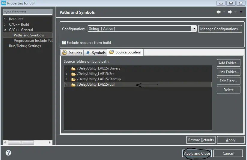
The folder will be added to your project. However, it’s not considered as a source code directory, so it won’t be compiled and give you a linking error in the linking stage if you call any of its functions. Right-click the util folder and click properties. And navigate to C/C++ paths and symbols, and source locations tab.

In the source locations tab, click add folder and add our util folder.
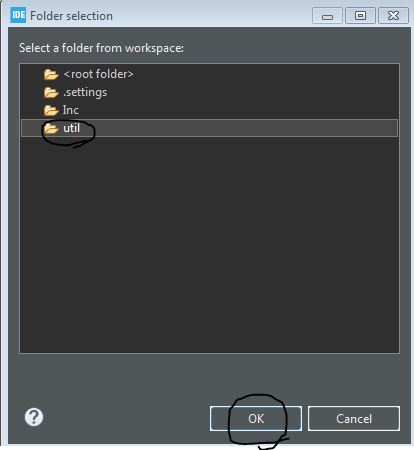 |  |
That’s it, now it’s properly added to our project build paths and can be included in the application code (in main.c).
Step #8
The Last step is to remove the timer config function static void MX_TIM4_Init(void) from the main.c file .
Make sure to name the timer instance correctly in the TimerDelay.c file (if using TIMER4, keep it as TIM4, otherwise, you can change the number according to the timer module’s number that you’re using instead).
#define TIMER TIM4
STM32 Delay Example Code (STM32 Timer Delay)
Note that the MX_TIM4_Init() function is deleted and never called. The timer initialization is now done in the TimerDelay_Init() function instead.
#include "main.h"
#include "../util/Timer_Delay.h"
#include "../util/DWT_Delay.h"

void SystemClock_Config(void);
static void MX_GPIO_Init(void);

int main(void)
{
    HAL_Init();
    SystemClock_Config();
    MX_GPIO_Init();
    /* Initialize The TimerDelay*/
    TimerDelay_Init();

    while (1)
    {
    	HAL_GPIO_TogglePin(GPIOA, GPIO_PIN_0);
    	delay_ms(100);
    }
}
STM32 Delay Example Code (STM32 DWT Delay)
Or you can use the STM32 DWT Delay by trying the application code below instead.
#include "main.h"
#include "../util/Timer_Delay.h"
#include "../util/DWT_Delay.h"

void SystemClock_Config(void);
static void MX_GPIO_Init(void);

int main(void)
{
    HAL_Init();
    SystemClock_Config();
    MX_GPIO_Init();
    /* Initialize The DWT_Delay*/
    DWT_Delay_Init();

    while (1)
    {
    	HAL_GPIO_TogglePin(GPIOA, GPIO_PIN_0);
    	DWT_Delay_ms(100);
    }
}
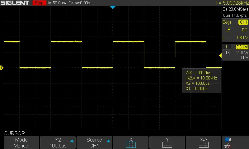
STM32 Delay Example Testing Results
Here are some screenshots from my DSO showing the timing for various signals. 1uSec, 10uSec, 100uSec, 1mSec delays. And how accurate it actually is. The DWT delay has shown similar results to the timer functions, they are nearly identical. However, the timer delay is much more accurate at the low end very short 1uSec delay. But all in all, it’s as good as it can be.
| 1µs | 10µs |
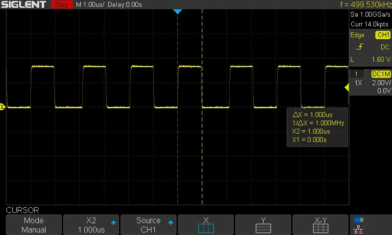 | 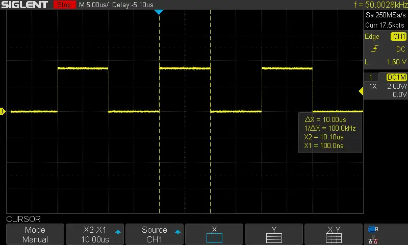 |
| 100µs | 1ms |
 | 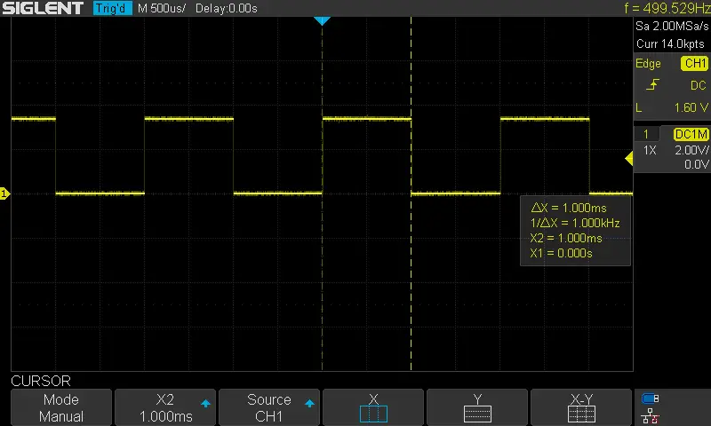 |
Required Parts For STM32 Examples
All the example Code/LABs/Projects in this STM32 Series of Tutorials are done using the Dev boards & Electronic Parts Below:
| QTY. | Component Name | Amazon.com | AliExpress | eBay |
| 1 | STM32-F103 BluePill Board (ARM Cortex-M3 @ 72MHz) | Amazon | AliExpress | eBay |
| 1 | Nucleo-L432KC (ARM Cortex-M4 @ 80MHz) | Amazon | AliExpress | eBay |
| 1 | ST-Link V2 Debugger | Amazon | AliExpress | eBay |
| 2 | BreadBoard | Amazon | AliExpress | eBay |
| 1 | LEDs Kit | Amazon & Amazon | AliExpress | eBay |
| 1 | Resistors Kit | Amazon & Amazon | AliExpress | eBay |
| 1 | Capacitors Kit | Amazon & Amazon | AliExpress & AliExpress | eBay & eBay |
| 1 | Jumper Wires Pack | Amazon & Amazon | AliExpress & AliExpress | eBay & eBay |
| 1 | Push Buttons | Amazon & Amazon | AliExpress | eBay |
| 1 | Potentiometers | Amazon | AliExpress | eBay |
| 1 | Micro USB Cable | Amazon | AliExpress | eBay |
★ Check The Links Below For The Full Course Kit List & LAB Test Equipment Required For Debugging ★
Download Attachments
You can download all attachment files for this Article/Tutorial (project files, schematics, code, etc..) using the link below. Please consider supporting our work through the various support options listed in the link down below. Every small donation helps to keep this website up and running and ultimately supports the whole community.
Wrap Up
In conclusion, we’ve discussed how the STM32 DWT delay can be implemented as well as the STM32 Timer delay. The provided util library includes both implementations for the DWT-based delay and the Timer-based delay. The newer version of the util library has Systick Timer-based delay functions which makes it more portable and easy to use than the older version presented in this tutorial.
If you’re just getting started with STM32, you need to check out the STM32 Getting Started Tutorial here.
Follow this STM32 Series of Tutorials to learn more about STM32 Microcontrollers Programming.
Gracias Brother, Saludos desde mi amada Venezuela.
Hello Mr.Magdy
your tutorials on STM32 as far as I know are the most diverse and thorough tutorials I could found however it could be a bit more noob friendly(as someone who has started learning microcontrollers from stm32 not Arduino or PIC)
now the question is how do we create several pulse trains with 1us resolution in the background without interfering with while() loop?
let’s say we need 10 pulse channels
one of them is carrier so the others are with respect to the first one and we can vary the delay and pulse width of them on the fly
but they all operate in the background without consuming much processing power
so we can write other stuff in the while() loop
If i got your question right, then I think you can operate the PWM module in synchronized mode so that you have one master channel and the others will be in sync with its timing. Independent edge mode will also enable you to add any time shift in any channel and vary its duty cycle on the run.
Why you use name like “au16_ms” ? In hungarian notation “a” mean array.
You’re right, it’s a type I guess. We typical use “a” for arrays, “u” for unsigned, “g” for global, etc.
Some of these rules are in the MISRA C and others are defined internally in each organization for their own standards.
Great article, thank you
however, doesn’t DWT stand for Data Watchpoint and Trace, and not Data Watchpoint Trigger?