In this tutorial, we’ll discuss how to configure the STM32 timer module to generate timer interrupts with a couple of example projects (Timer Mode). You’ll go through step-by-step HAL example configurations to initialize all the required hardware peripherals. Then, we’ll write simple application code to test the hardware functionalities. And also we’ll see how to calculate the timer preload value to get the desired output time interval exactly. without further ado, let’s get started!
Table of Contents
- STM32 Timer Calculation & Equation Formula
- STM32 Timer Interrupt Example (LAB)
- STM32 Timer Interrupt Example Project (Steps)
- STM32 Timer Interrupt Example Code in CubeMX IDE
- Testing The STM32 Timer Example Project
- STM32 Timer Fine-Timing Experiment
- Using STM32 Timer Interrupt Calculator
- Wrap Up
STM32 Timer Calculation & Equation Formula
In this LAB, we’ll set up a general-purpose timer module to operate in timer mode. We’ll set the overflow time interval to the desired value using the equation below. And toggle an LED in the interrupt service routine (ISR) for the timer overflow event.
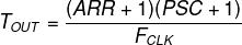
As you can see, the output time interval is determined by the Prescaler value, the clock frequency, and the timer auto-reload register’s value. Given that the blue pill board can run @ up to 72MHz, so let’s set the frequency to 72Mz. Now, we can choose a value for the Prescaler then put in the desired TOUT and solve for the auto-reload register’s value.
In LAB7, we’ll set our desired output time interval to be 100ms. We’ll toggle the LED once each 100ms and we’d like to set up the timer interrupt to give us this time interval. So, from the above equation, we can set the FCLK to be 72MHz. And let the Prescaler be 999. Now, the only unknown is the auto-reload (ARR) value. By solving for it, we’ll get 7199.

STM32 Timer Interrupt Example (LAB)
| LAB Number | 7 |
| LAB Title | Timer Mode Periodic Event |
- Configure the general-purpose timer (TIM2) to operate in timer mode
- Set The Prescaler, and the Preload value so that the output Time interval is 100ms
- Toggle an output pin (LED) each 100ms in the timer overflow ISR
- Measure and verify the output signal’s timing
STM32 Timer Interrupt Example Project (Steps)
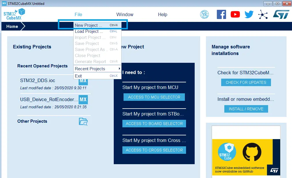
Step1: Open CubeMX & Create New Project
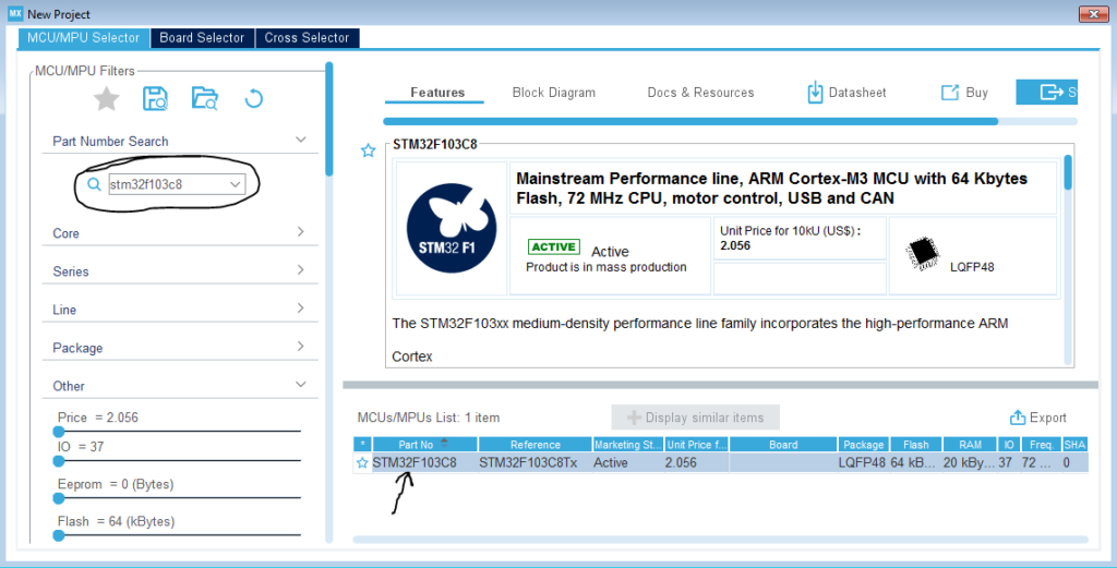
Step2: Choose The Target MCU & Double-Click Its Name
Step3: Click On The Pin You Want To Configure As An Output & Select Output Option
Let it be B13 pin for example! (The onBoard LED Pin)
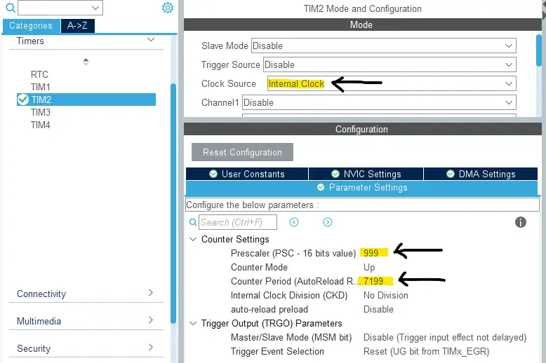
Step4: Configure Timer2 Peripheral
As we’ve calculated earlier, the Prescaler will be 999, and the Preload value will be 7199. And the timer module will be clocked at the internal clock frequency.
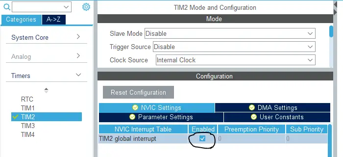
Step5: Enable The Timer Interrupt Signal In NVIC Tab
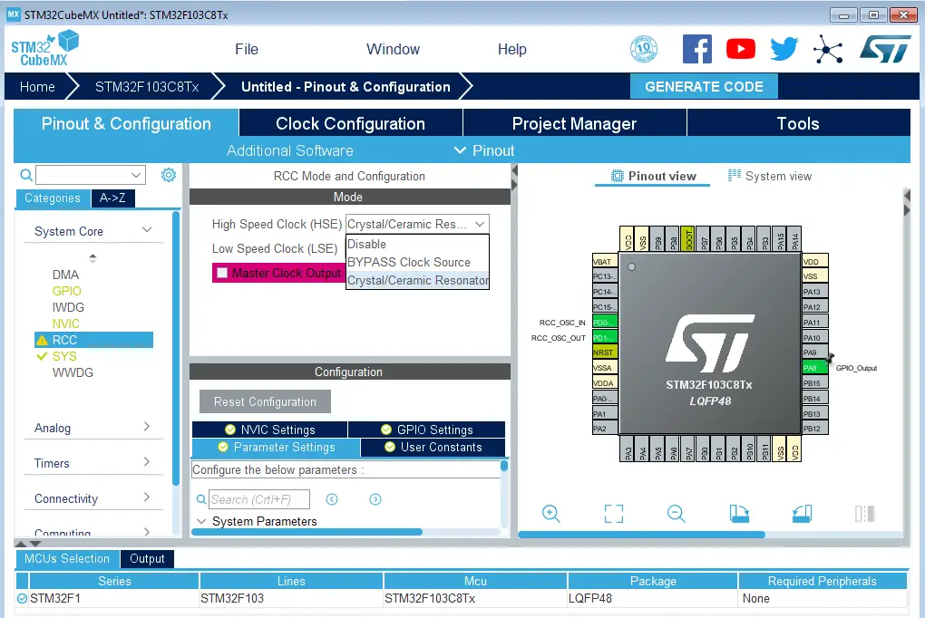
Step6: Set The RCC External Clock Source
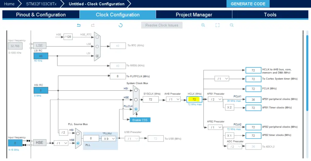
Step7: Go To The Clock Configuration
Step8: Set The System Clock To Be 72MHz Or Whatever You Want
Step9: Name & Generate The Project Initialization Code For CubeIDE or The IDE You’re Using
Then, open the project in the IDE you’re using. And head over to the main.c file. So we can start writing the application code and have a look at the initialization code generated by the STM32 CubeMX tool.
STM32 Timer Interrupt Example Code in CubeMX IDE
Here is the generated initialization code in the main.c file
#include "main.h"

TIM_HandleTypeDef htim2;

void SystemClock_Config(void);
static void MX_GPIO_Init(void);
static void MX_TIM2_Init(void);

int main(void)
{

  HAL_Init();
  SystemClock_Config();
  MX_GPIO_Init();
  MX_TIM2_Init();

  while (1)
  {

  }

}
Now, the application we’re currently developing is an LED toggle in the ISR for the timer module. So, open the stm32f1xx_it.c file to find the timer interrupt handler, which is this function TIM2_IRQHandler(). Hover over the HAL_TIM_IRQHandler() function and right-click to navigate to its implementation.
void TIM2_IRQHandler(void)
{

  HAL_TIM_IRQHandler(&htim2);

}
After navigating to the timer interrupt handler routine, you’ll find the following implementation. In this code, we’re searching for the callback function’s name that gets called when an overflow interrupt occurs. You can notice that all sources share the same interrupt signal output compare match, overflow, input capture, etc.
void HAL_TIM_IRQHandler(TIM_HandleTypeDef *htim)
{
  // Other timer interrupts events..
  //..
  //..
  //..
  /* TIM Update event */
  if (__HAL_TIM_GET_FLAG(htim, TIM_FLAG_UPDATE) != RESET)
  {
    if (__HAL_TIM_GET_IT_SOURCE(htim, TIM_IT_UPDATE) != RESET)
    {
      __HAL_TIM_CLEAR_IT(htim, TIM_IT_UPDATE);
      #if (USE_HAL_TIM_REGISTER_CALLBACKS == 1)
        htim->PeriodElapsedCallback(htim);
      #else
        HAL_TIM_PeriodElapsedCallback(htim);
      #endif /* USE_HAL_TIM_REGISTER_CALLBACKS */
    }
  }
  //..
  //..
  // Other timer interrupts events..
}
Now, we’ve got the callback function’s name that gets called whenever timer overflow occurs. It’s HAL_TIM_PeriodElapsedCallback(). So, we’ll write our own implementation for it in the application file ( main.c). And a mention-worthy point is that you also have to enable (start) the timer so it gets clocked and starts counting, otherwise, it’ll remain IDLE.
Full LAB Code (main.c)
#include "main.h"

TIM_HandleTypeDef htim2;

void SystemClock_Config(void);
static void MX_GPIO_Init(void);
static void MX_TIM2_Init(void);

int main(void)
{

  HAL_Init();
  SystemClock_Config();
  MX_GPIO_Init();
  MX_TIM2_Init();
  HAL_TIM_Base_Start_IT(&htim2);

  while (1)
  {

  }

}

void HAL_TIM_PeriodElapsedCallback(TIM_HandleTypeDef* htim)
{
    HAL_GPIO_TogglePin(GPIOB, GPIO_PIN_13);
}
Build & Flash The Code And Let’s Test The Results!
Testing The STM32 Timer Example Project
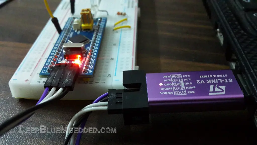
Step0: Refer To The Blue Pill Board Schematic & Pinout
Step1: Connect The ST-Link To The USB Port & SWD Pins On Board
Step2: Click The Debug Button To Compile The Code & Flash It To The Board & Start A Debugging Session
Step3: You Can Stop The Debugging Session Or Keep It Going. But You Need To Restart The MCU Once To Run The New Application At The Booting Process.
The Results of This LAB
Test Video
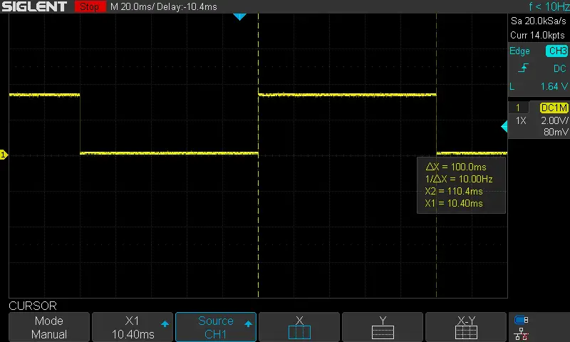
Output Signal On My DSO
It’s a perfect 100ms time interval.
STM32 Timer Fine-Timing Experiment
| LAB Number | 8 |
| LAB Title | Timer Mode Periodic Event (in microseconds) |
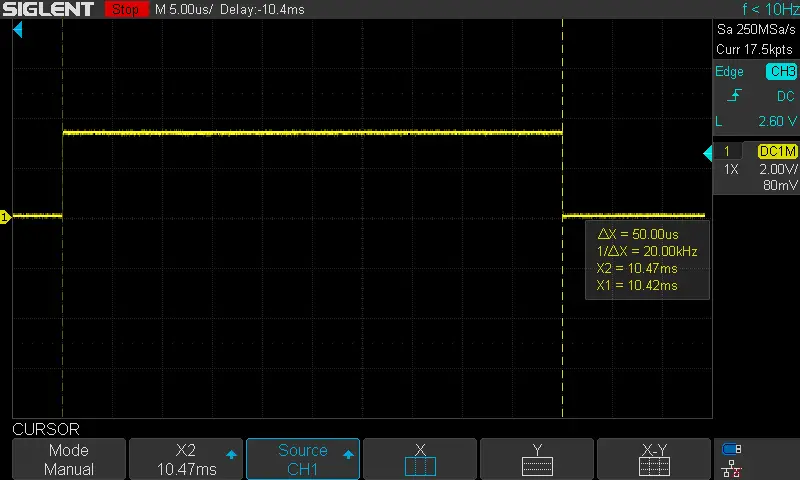
I’ve also done a couple of other experiments in which “fine” output time intervals are desired (from 50μs down to 1μs). The first of which was to produce a periodic timer interrupt every 50μSec. Hence the FCLK is 72MHz, and the Prescaler is left as 0 which means 1:1, therefore the auto-reload register’s value is found to be 3599 using the timer formula.
Consequently, I changed these values in the code, rebuilt & flashed it. And the result was a clean 50μSec waveform! As you can see in the screenshot below.
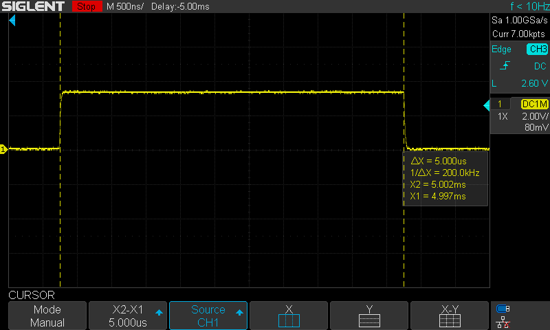
Obviously, by changing the auto-reload register’s value from 3599 to 359, the output time interval should now be 5μSec. So, I did that, rebuilt & flashed the code. The result was as expected a clean 5μSec time interval as you can see in the screenshot down below.
However, I do believe that there is a fundamental limitation for the timing resolution that can be enhanced by reducing the usage of HAL library functions and calling multiple functions in the process of handling various tasks.
Using STM32 Timer Interrupt Calculator
This STM32 Timer Calculator online tool that we’ve built will help you find the optimal prescaler (PSC) and auto-reload (ARR) register values to generate your desired timer interrupt intervals with a click of a button. Give it a try and keep this Embedded Systems Calculators & Utilities page in your bookmarks to help you find these tools much quicker.
Here is an example usage for the STM32 Timer Calculator where I wanted to generate a 10ms time interval using a 72MHz clock source.

To verify the result, we’ll use the timer formula as usual: TOUT = (ARR+1)(PSC+1)/72MHz = (12×60000)/72000000 = 10ms (Exactly)
Required Parts For Example LABs
All the example code/LABs/projects in the series of tutorials are done using the dev boards below:
- Nucleo32-L432KC (ARM Cortex-M4 @ 80MHz) or (eBay)
- Blue Pill STM32-F103 (ARM Cortex-M3 @ 72MHz) or (eBay)
- ST-Link v2 Debugger or (eBay)
| QTY# | Component Name | ???? Amazon.com | ???? eBay.com |
| 2 | BreadBoard | Amazon | eBay |
| 1 | LEDs Kit | Amazon Amazon | eBay |
| 1 | Resistors Kit | Amazon Amazon | eBay |
| 1 | Capacitors Kit | Amazon Amazon | eBay & eBay |
| 2 | Jumper Wires Pack | Amazon Amazon | eBay & eBay |
| 1 | 9v Battery or DC Power Supply | Amazon Amazon Amazon | eBay |
| 1 | Micro USB Cable | Amazon | eBay |
| 1 | Push Buttons | Amazon Amazon | eBay |
★ Check The Full Course Complete Kit List & LAB Test Equipment Required For Debugging
Download Attachments
You can download all attachment files for this Article/Tutorial (project files, schematics, code, etc..) using the link below. Please consider supporting my work through the various support options listed in the link down below. Every small donation helps to keep this website up and running and ultimately supports our community.
Wrap Up
To conclude this tutorial, we’d like to highlight the fact that the STM32 hardware timers can easily be configured to generate periodic timer interrupt events that we’ll heavily depend on in a later tutorial while making our way to develop real-time systems with STM32 microcontrollers. This tutorial is a fundamental part of our STM32 Series of Tutorials because we’ll use it in many tutorials and projects hereafter. So make sure, you’ve learned all the concepts and implemented the practice examples.
If you’re just getting started with STM32, you need to check out the STM32 Getting Started Tutorial here.
And follow this STM32 Series of Tutorials to learn more about STM32 Microcontrollers Programming.
| Previous Tutorial | Tutorial 13 | Next Tutorial | |||||
Great post! The step-by-step explanation of setting up timer interrupts using HAL in STM32 is really helpful. I especially appreciated the code snippets; they made it easy to follow along. Looking forward to more articles like this!
when i write anything in the while(1) void callback function is not exeucting
Great post! The example on setting up the timer interrupt using the HAL library is really helpful. I appreciate the clear explanations and the detailed code snippets. It made understanding the timer mode much easier. Looking forward to more tutorials like this!
You write “Hover over the HAL_TIM_IRQHandler() function and right-click to navigate to its implementation.”
This doesn’t work with me here (STM32CubeIDE 1.18.0). Right click give me a popup menu. How is te exact protocol to navigate to the implementation?
Hello Christoph,
Yeah, I noticed that It’s different in the new STM32Cube IDE version. Please, try the following:
Hover over the function until it’s “Highlighted”, then righ-click and select “Open Declaration” or press the “F3” key on your keyboard. This should do it
Best regards,
Khaled M.