| Previous Tutorial | Tutorial 44 | Next Tutorial | |||||
| STM32 I2C Communication Tutorial – HAL Examples | |||||||
| STM32 Course Home Page ???? | |||||||
In this tutorial, we’ll be discussing the I2C hardware in STM32 microcontrollers. Starting with an introduction to the Inter-Integrated Circuit (I2C) communication. And we’ll get a closer look at the STM32 I2C hardware module and its internal functionalities, modes of operation, options, and configurations. In conclusion, we’ll take a look at the possible interrupt signals that can be triggered by the I2C hardware. And the different modes to perform I2C transmit & receive operations like (polling – interrupt – DMA) both as an I2C master and as a slave device as well.
Finally, we’ll check the available I2C configuration inside of CubeMX and how to configure & operate the peripheral using the provided HAL APIs. And that’s it for this theoretical tutorial. Next, we’ll do a handful of LABs to practice using I2C in different projects for communication and modules interfacing with STM32 microcontrollers.
[toc]
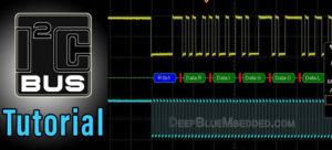
1. Introduction To I2C Communication
I2C (i-square-c) is an acronym for “Inter-Integrated-Circuit” which was originally created by Philips Semiconductors (now NXP) back in 1982. I2CTM is a registered trademark for its respective owner and maybe it was the reason they call it “Two Wire Interface (TWI)” in some microcontrollers like Atmel AVR. The I2C is a multi-master, multi-slave, synchronous, bidirectional, half-duplex serial communication bus. It’s widely used for attaching lower-speed peripheral ICs to processors and microcontrollers in short-distance, intra-board communication.
I2C Modes & Bus Speeds
Originally, the I2C-bus was limited to 100 kbit/s operations. Over time there have been several additions to the specification so that there are now five operating speed categories. Standard-mode, Fast-mode (Fm), Fast-mode Plus (Fm+), and High-speed mode (Hs-mode) devices are downward-compatible. This means any device may be operated at a lower bus speed. Ultra Fast-mode devices are not compatible with previous versions since the bus is unidirectional.
Bidirectional bus:
- Standard-Mode (Sm), with a bit rate up to 100 kbit/s
- Fast-Mode (Fm), with a bit rate up to 400 kbit/s
- Fast-Mode Plus (Fm+), with a bit rate up to 1 Mbit/s
- High-speed Mode (Hs-mode), with a bit rate up to 3.4 Mbit/s.
Unidirectional bus:
- Ultra Fast-Mode (UFm), with a bit rate up to 5 Mbit/s
Note: You have to refer to the specific device datasheet to check the typical details for the i2c hardware specifications that have actually been implemented on-chip.
I2C Physical Layer (Hardware)
The I2C bus uses what’s known as an open-drain (open-collector) output driver for both SDA and SCL lines. Which as the name suggests is having each IO pin connected to the collector of the output driver transistor internally, while having it pulled up to Vcc with a resistor eternally. That’s why the default (IDLE) state for each line is HIGH when the open-drain driver is turned OFF. However, if we turn ON the output driver, the IO pin is driven LOW to the ground by the output driver transistor as you can see in the diagram below.
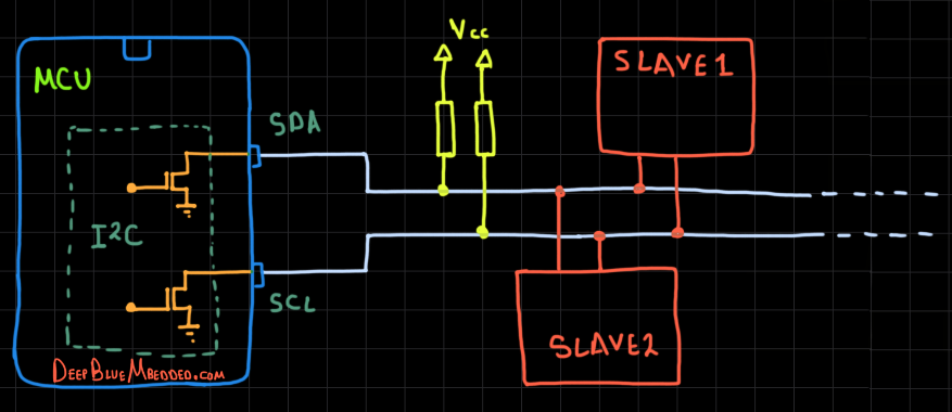
The I2C bus lines being “open-drain” bidirectional pins makes it perfect for multi-master multi-slave sort of communication without any risk of having collisions. And that’s due to having what’s called “Bus Arbitration” in case of multiple masters did initiate a transaction at the exact same time.
Anyone will write a 0 first while the other is writing a 1, will win the arbitration and continue its message and the other master will stop and wait till the end. That’s because of the nature of “Open-drain” output. To write a 0, we turn ON the output driver to pull the signal line to LOW. To write a 1, we turn OFF the output driver and the line will be pulled up to HIGH by the effect of the external resistors. That’s why bus arbitration is a very powerful feature for I2C communication.
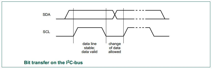
SDA & SCL, Data Validity
Both SDA and SCL are bidirectional lines, connected to a positive supply voltage via a current-source or pull-up resistor. When the bus is free, both lines are HIGH. The output stages of devices connected to the bus must have an open-drain or open-collector to perform the wired-AND function.
Due to the variety of different technology devices (CMOS, NMOS, bipolar), that can be connected to the I2C-bus, the levels of the logical ‘0’ (LOW) and ‘1’ (HIGH) are not fixed and depend on the associated level of VDD. Input reference levels are set as 30 % and 70 % of VDD; VIL is 0.3VDD and VIH is 0.7VDD. The data on the SDA line must be stable during the HIGH period of the clock. The HIGH or LOW state of the data line can only change when the clock signal on the SCL line is LOW. One clock pulse is generated for each data bit transferred.
Elements of I2C Transactions
A typical I2C message consists of some basic elements (conditions) that take place on the I2C bus sequentially and it always starts with a start condition (s). Followed by the desired slave device address (7-Bits or 10-Bits), then a R/W bit to determine whether the master (who initiated the S condition for communication) wants to read or write to this slave having that address. Then if the slave exists and works OK, it’ll acknowledge back to the master by sending an Acknowledge bit ACK otherwise, it’s considered a Negative Acknowledge NACK. Afterward, the byte of Data is sent, followed by an acknowledge from the slave. And finally, the master can terminate the communication by sending the Stop Condition (P) sequence.
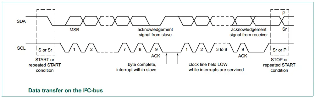
We can summarize these conditions (elements) of I2C bus signaling as follows:
- Start Condition (S)
- Stop Condition (P)
- Repeated Start (Restart) Condition (Sr)
- Acknowledge ACK (A)
- Not Acknowledge NACK (~A)
- Address + R/W
- Data Byte
Other topics and details of the I2C mechanics of its operation are discussed in detail in the article down below. Including I2C clock synchronization, stretching, I2C bus arbitration, addressing, I2C bus conditions, and more.
| Check this in-depth tutorial for more information about I2C serial communication | |
 |
 |
The linked I2C tutorial above is a full guide (+12k words!) that has all the information you may need to know if you’re just starting to learn about the topic. Take the time to check it out if you need to and come back to resume this tutorial and to see the I2C hardware peripheral implemented in STM32 microcontrollers and the extra features it does have. Then, we can proceed to build embedded software applications with an I2C interface to read sensors, external memories, etc.
2. I2C Hardware In STM32
2.1 STM32 I2C Hardware Overview
I2C (inter-integrated circuit) bus Interface serves as an interface between the microcontroller and the serial I2C bus. It provides multi-master capability and controls all I2C bus-specific sequencing, protocol, arbitration, and timing. It supports the standard mode (Sm, up to 100 kHz) and Fm mode (Fm, up to 400 kHz).
It may be used for a variety of purposes, including CRC generation and verification, SMBus (system management bus), and PMBus (power management bus). Depending on specific device implementation DMA capability can be available for reduced CPU overload.
2.2 STM32 I2C Main Features
- Multimaster capability: the same interface can act as Master or Slave
- I2C Master features: [ Clock generation – Start and Stop generation]
- I2C Slave features: [Programmable I2C Address detection – Dual Addressing Capability to acknowledge 2 slave addresses – Stop bit detection]
- Generation and detection of 7-bit/10-bit addressing and General Call
- Supports different communication speeds:
– Standard Speed (up to 100 kHz)
– Fast Speed (up to 400 kHz) - Analog noise filter
- 2 Interrupt vectors:
– 1 Interrupt for successful address/ data communication
– 1 Interrupt for error condition - Optional clock stretching
- 1-byte buffer with DMA capability
- Configurable PEC (packet error checking) generation or verification:
- SMBus 2.0 Compatibility
- PMBus Compatibility
3. STM32 I2C Hardware Functionalities
In this section, we’ll get a deep insight into the STM32 I2C module hardware, its block diagram, functionalities, modes of operations, and data reception/transmission.
3.1 STM32 I2C Block Diagram
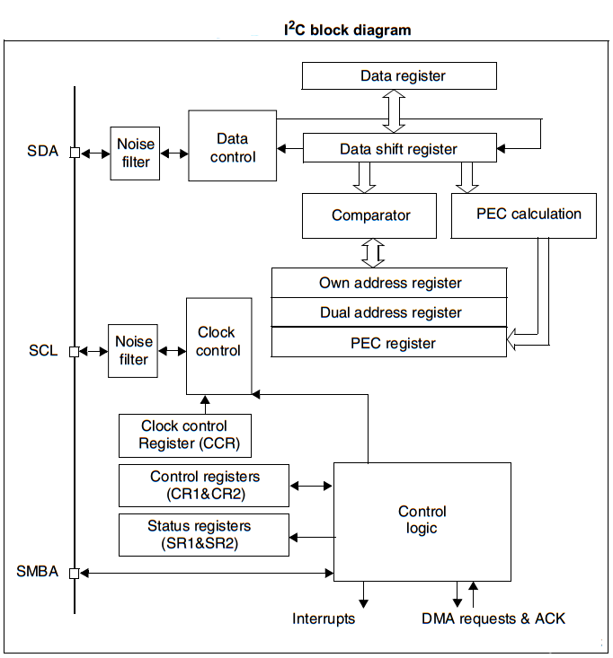
As you can see in the I2C block diagram above, there is the main shift register, a buffer register, and some control logic units to handle all I2C transaction steps. Just like address match checking, generating the clock signal, filtering, error checking, and so on.
3.2 STM32 I2C Mode Selection
The interface can operate in one of the four following modes:
- Slave transmitter
- Slave receiver
- Master transmitter
- Master receiver
By default, it operates in slave mode. The interface automatically switches from slave to master, after it generates a START condition and from master to slave, if an arbitration loss or a Stop generation occurs, allowing multi-master capability. We’ll be creating a handful of example projects to operate the I2C peripheral in each one of all the 4 modes mentioned above.
3.3 STM32 I2C In Slave Mode
By default, the I2C interface operates in Slave mode. To switch from default Slave mode to Master mode a Start condition generation is needed. The peripheral input clock must be programmed in the I2C_CR2 register in order to generate correct timings. The peripheral input clock frequency must be at least:
- 2 MHz in Sm mode
- 4 MHz in Fm mode
As soon as a start condition is detected, the address is received from the SDA line and sent to the shift register. Then it is compared with the address of the interface. Following the address reception and after clearing ADDR, the slave receives bytes from the SDA line into the DR register via the internal shift register. After each byte, the interface generates an acknowledge pulse if the ACK bit is set.
If RxNE is set and the data in the DR register is not read before the end of the next data reception, the BTF bit is set and the interface waits until BTF is cleared by a read from I2C_SR1 followed by a read from the I2C_DR register, stretching SCL low. Clock stretching is essentially holding the clock line SCL LOW by the slave device which prevents any master device on the I2C bus from initiating any new transaction until that slave releases the SCL back again. That’s why you should be careful when using clock stretching in slave devices.
After the last data byte is transferred a Stop Condition is generated by the master. The interface detects this condition and sets the STOPF bit and generates an interrupt if the ITEVFEN bit is set. The STOPF bit is cleared by a read of the SR1 register followed by a write to the CR1 register.
3.4 STM32 I2C In Master Mode
In Master mode, the I2C interface initiates a data transfer and generates the clock signal. A serial data transfer always begins with a Start condition and ends with a Stop condition.
Master mode is selected as soon as the Start condition is generated on the bus with a START bit. The following is the required sequence in master mode.
- Program the peripheral input clock in I2C_CR2 Register in order to generate correct timings
- Configure the clock control registers
- Configure the rise time register
- Program the I2C_CR1 register to enable the peripheral
- Set the START bit in the I2C_CR1 register to generate a Start condition
The peripheral input clock frequency must be at least:
- 2 MHz in Sm mode
- 4 MHz in Fm mode
3.5 STM32 I2C PEC (Packet Error Checking)
A PEC calculator has been implemented by STMicroelectronics in I2C hardware to improve the reliability of communication. The PEC is calculated by using the C(x) = x8 + x2 + x + 1 CRC-8 polynomial serially on each bit. By enabling PEC, you can have automatic error checking for large data packet transactions all done by hardware without adding any overhead on the software side.
However, you should also know that if the master device did lose the “arbitration” at any instance, this will corrupt the PEC. And the device will be set back to slave mode and waits until the arbitration “winner” master device finishes its message. Only then, you can start the process all over again.
4. STM32 I2C Error Conditions
There are some error conditions that could be detected by the I2C interface hardware to indicate some issues on the hardware level. The software can easily detect those error conditions by reading the corresponding flag bits for each error signal. The error conditions include:
Bus Error (BERR) – This error occurs when the I2C interface detects an external Stop or Start condition during an address or a data transfer.
Acknowledge Failure (AF) – This error occurs when the interface detects a non-acknowledge bit.
Arbitration Lost (ARLO) – This error occurs when the I2C interface detects an arbitration lost condition.
Overrun/Underrun Error (OVR) – An overrun error can occur in slave mode when clock stretching is disabled and the I2C interface is receiving data. The interface has received a byte and the data in DR has not been read before the next byte is received by the interface. Underrun error can occur in slave mode when clock stretching is disabled and the I2C interface is transmitting data. The interface has not updated the DR with the next byte before the clock comes for the next byte.
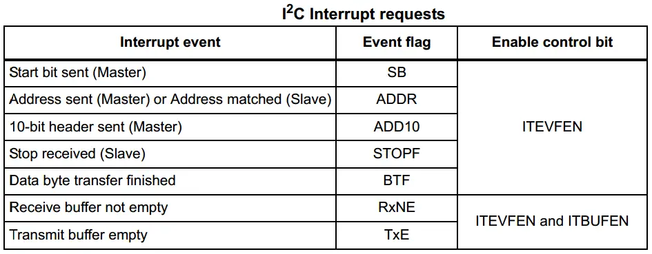
5. STM32 I2C Interrupts
The I2C interrupt events are connected to the same interrupt vector. So the I2C fires a single interrupt signal regardless of the source of it. The software will have to detect it. These events generate an interrupt if the corresponding Enable Control Bit is set.
6. STM32 I2C Master – Slave Modes TX & RX
In this section, I’ll list the possible ways that you can handle I2C transactions in your firmware applications. For code example LABs and testing, just click on the next tutorial button and keep going through this series of tutorials. There will be lots of examples and libraries that we’ll build based on I2C communication (e.g I2C_LCD, OLED, MPU6050 IMU, etc…).
I2C With Polling
The first and the easiest way to do anything in embedded software is just to poll for the hardware resource until it’s ready to move on to the next step in your program instructions. However, it’s the least efficient way to do things and the CPU will end up wasting so much time in a “busy-waiting” state.
It’s the same thing for both transmission and reception. You just wait until the current byte of data to be transmitted so you can start the next one and so on.
I2C With Interrupts
We can, however, enable the I2C interrupts and have a signal when it’s done and ready for servicing by CPU. Either for data that has been sent or received. Which saves a lot of time and has been always the best way to handle events like that.
However, in some “Time Critical” applications we need everything to be as deterministic, in time, as possible. And a major problem with interrupts is that we can’t expect when it’d arrive or during which task. That can potentially screw up the timing behavior of the system.
I2C With DMA
To operate at its maximum speed, the I2C needs to be fed with the data for transmission and the data received on the Rx buffer should be read to avoid overrun. To facilitate the transfers, the I2C features a DMA capability implementing a simple request/acknowledge protocol.
DMA requests are generated by Data Register becoming empty in transmission and Data Register becoming full in reception. Using the DMA will also free the CPU from doing the data transfers “peripheral <-> memory”. This will end up saving a lot of time and is considered to be the most efficient way to handle this peripheral to memory data transfer and vice versa.
7. STM32 I2C Device Memory Read / Write
In this section, I’ll explain a useful feature that has been implemented in HAL APIs for the I2C driver firmware library which is the device memory read/write. The following are the (Blocking) version for both of the 2 functions.
|
1 2 |
HAL_I2C_Mem_Write(); HAL_I2C_Mem_Read(); |
There are other versions for other modes of operation like interrupt and interrupt+DMA. But let’s first explain what is the device memory read/write operation.
We, the developers, basically don’t need to do anything on the hardware level for the I2C interface to get it to work. The details of I2C operation mentioned earlier in this tutorial are mostly to give you an understanding of what’s happening at the hardware level. Despite the fact that most of those operations are done automatically by hardware when we set/clear some control bits.
Therefore, we only need to call some basic functions that represent a wrapper layer for the control registers set/clear bits sort of configuration. Just to get the I2C interface properly configured and also initiate data transmission/reception operations.
The basic functionality for transmitting data over I2C as a Master device is handled by the following HAL function.
|
1 |
HAL_I2C_Master_Transmit(); |
It sends some data over I2C to a specific slave device address on the bus (if found) in a blocking mode. So, what’s the difference between the normal I2C_Transmit and I2C_Mem_Write? That’s what we’re trying to answer in this section. For that, let’s consider as an example the MPU6050 IMU device.
The IMU has an internal I2C device address so that any master on the bus can easily address this sensor module. Internally, the MPU6050 itself has some registers with a unique address for each of them. Generally speaking, we need to set some values for the internal registers of the IMU in order to configure it as per our application, and also read some registers in which the IMU data is located.
So, if you’ve got a master STM32 uC and would like to get the readings of the MPU6050 IMU, you’d need to do the following as stated in the datasheet.
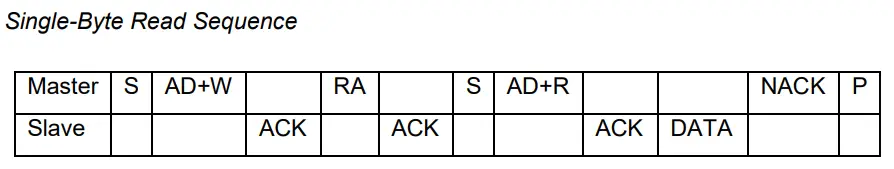
As you can see, the Master (STM32 uC) has to start the transaction. Then send the AD+W (the address of the MPU6050 module itself) for writing operation. The master then writes out the internal register address (RA) inside the MPU6050 that we’d like to read. The slave will therefore acknowledge the command and send out the data located in that specific register. Finally, the master will terminate the communication.
This is how to read a register at a specific address inside a module that has its unique address as well on the I2C bus!
You can do all of that manually with the provided basic HAL APIs or use the Mem_Write / Mem_Read collection of functions that support all modes (blocking – interrupt – DMA). We’ll be putting all of those functions under testing in the upcoming tutorials and LABs to get more familiar with them.
8. SPI Configuration In CubeMX
In the next few tutorials, we’ll be doing some practical LABs to implement I2C Master/Slave (TX & RX) code examples. In which we’ll be using the CubeMX software tool to configure the I2C hardware. Therefore, in this section, I’ll introduce to you the features and options that can be configured within CubeMX GUI for I2C peripheral.
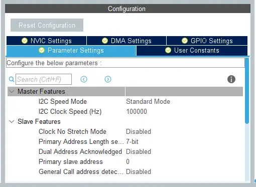
Here is the configuration tab for the I2C peripheral in CubeMX. And those are the possible modes for I2C.
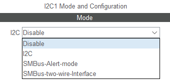
Let’s pick the “I2C” mode. Now, you’ll find that we’re able to set the clock rate for master mode. And if you’re going to operate in slave mode, you can set the I2C device address length & value, and enable/disable the clock stretching feature that we’ve discussed earlier.
We can also enable/disable interrupts for I2C in the NVIC tab if you’re willing to use interrupt mode instead of polling the peripheral. And the same goes for the DMA, you can click the DMA tab to “Add” a DMA channel dedicated to I2C transfer and configure its parameters.
9. STM32 I2C HAL Functions APIs
1. STM32 I2C “Blocking” HAL Functions (Blocking Mode)
Master Transmission
|
1 |
HAL_I2C_Master_Transmit (I2C_HandleTypeDef * hi2c, uint16_t DevAddress, uint8_t* pData, uint16_t Size, uint32_t Timeout); |
Master Reception
|
1 |
HAL_I2C_Master_Receive (I2C_HandleTypeDef * hi2c, uint16_t DevAddress, uint8_t* pData, uint16_t Size, uint32_t Timeout); |
Slave Transmission
|
1 |
HAL_I2C_Slave_Transmit (I2C_HandleTypeDef * hi2c, uint8_t * pData, uint16_t Size, uint32_t Timeout); |
Slave Reception
|
1 |
HAL_I2C_Slave_Receive (I2C_HandleTypeDef * hi2c, uint8_t * pData, uint16_t Size, uint32_t Timeout); |
Device Memory Write
|
1 |
HAL_I2C_Mem_Write (I2C_HandleTypeDef * hi2c, uint16_t DevAddress, uint16_t MemAddress, uint16_t MemAddSize, uint8_t * pData, uint16_t Size, uint32_t Timeout); |
Device Memory Read
|
1 |
HAL_I2C_Mem_Read (I2C_HandleTypeDef * hi2c, uint16_t DevAddress, uint16_t MemAddress, uint16_t MemAddSize, uint8_t * pData, uint16_t Size, uint32_t Timeout); |
2. STM32 I2C Interrupt Mode HAL Functions (Non-Blocking Mode)
Master Transmission
|
1 |
HAL_I2C_Master_Transmit_IT (I2C_HandleTypeDef * hi2c, uint16_t DevAddress, uint8_t * pData, uint16_t Size); |
After calling the above function, the I2C peripheral will start sending all the data bytes in the buffer one by one until it’s done. When it’s done this function below will be called and executed, if you’d like to do something upon data transmission completion, then add that to your code in the application source file (main.c).
|
1 2 3 4 |
void HAL_I2C_MasterTxCpltCallback (I2C_HandleTypeDef * hi2c) { // TX Done .. Do Something! } |
Master Reception
|
1 |
HAL_I2C_Master_Receive_IT (I2C_HandleTypeDef * hi2c, uint16_t DevAddress, uint8_t * pData, uint16_t Size); |
After calling the above function, the I2C peripheral will start receiving all the incoming data bytes in the buffer one by one until it’s done. When it’s done this function below will be called and executed, if you’d like to do something upon data reception completion, then add that to your code in the application source file (main.c).
|
1 2 3 4 |
void HAL_I2C_MasterRxCpltCallback (I2C_HandleTypeDef * hi2c) { // RX Done .. Do Something! } |
Similar APIs are also available for slave mode of operation.
3. STM32 I2C DMA Mode HAL Functions (Non-Blocking Mode)
Master Transmission
|
1 |
HAL_I2C_Master_Transmit_DMA (I2C_HandleTypeDef * hi2c, uint16_t DevAddress, uint8_t * pData, uint16_t Size); |
After calling the above function, the I2C peripheral will start sending all the data bytes in the buffer one by one until it’s done (in DMA Mode). When it’s done this function below will be called and executed, if you’d like to do something upon data transmission completion, then add that to your code in the application source file (main.c).
|
1 2 3 4 |
void HAL_I2C_MasterTxCpltCallback (I2C_HandleTypeDef * hi2c) { // TX Done .. Do Something! } |
Master Reception
|
1 |
HAL_I2C_Master_Receive_DMA (I2C_HandleTypeDef * hi2c, uint16_t DevAddress, uint8_t * pData, uint16_t Size); |
After calling the above function, the I2C peripheral will start receiving all the incoming data bytes in the buffer one by one until it’s done (in DMA Mode). When it’s done this function below will be called and executed, if you’d like to do something upon data reception completion, then add that to your code in the application source file (main.c).
|
1 2 3 4 |
void HAL_I2C_MasterRxCpltCallback (I2C_HandleTypeDef * hi2c) { // RX Done .. Do Something! } |
Similar APIs are also available for slave mode of operation.
4. STM32 I2C Device Check
This is a useful utility to check if a slave device on the I2C is actually existing and working or not.
|
1 |
AL_I2C_IsDeviceReady (I2C_HandleTypeDef * hi2c, uint16_t DevAddress, uint32_t Trials, uint32_t Timeout); |
The I2C Communication Bus Demonstrated in This Tutorial Will Be Used In The Following Next Tutorials:
- MCU – MCU Communication Over I2C
- External Serial I2C EEPROM
- OLED Display
- I2C LED Interface
- and more…
That’s it for this tutorial. If you’d like to see the practical LAB examples for I2C and other interfacing projects and libraries we’ll build using this peripheral, just keep progressing through this series of tutorials and click to the next tutorial link down below.
Did you find this helpful? If yes, please consider supporting this work and sharing these tutorials!
Stay tuned for the upcoming tutorials and don’t forget to SHARE these tutorials. And consider SUPPORTING this work to keep publishing free content just like this!
| STM32 Course Home Page ???? |
|||||||
| Previous Tutorial | Tutorial 44 | Next Tutorial | |||||
Hi
could you make a tutorial about the use of the sequential I2C functions like.
HAL_I2C_Master_Seq_Receive_IT and HAL_I2C_Master_Seq_Transmit_IT.
I’m currently struggeling with those because my device wants commands for reading a register that are 4 bytes long.
And i can find no example on how to use them on google ????
Any help would be appreciated.
Martin
Hi
Thanks for this tutorial. I was quite excited to get into the actual projects but found that the “Next Tutorial” button doesn’t actually do anything. Is this a problem with the page or have the practical LAB examples for I2C not been added yet?
paul
Sorry but the example for blocking mode does not work on STM32H563VI.
Why not? the chip says it gets and error after the start bit is set on the SDA.
Pullups are installet. Compilation and debug start is ok. The init of the I2C
is ok (HAL:OK). But then nothig works.
using the HAL_I2C_Master_Transmit() seems to be a non operational command
relative to the actual processor.
Ideas?