In this tutorial, we’ll use the STM32 GPIO registers to configure & control the GPIO pins with direct register access. You’ll learn how to use STM32 register programming to configure & control the GPIO pin in a much faster way than using the HAL functions. Near the end of this tutorial, we’ll compare side-by-side the speed of register-based GPIO control functions Vs HAL GPIO write functions. Without further ado, let’s get right into it!
Table of Contents
- STM32 GPIO Registers
- STM32 GPIO Output (Direct Register Access)
- STM32 GPIO Input Read (Direct Register Access)
- STM32 GPIO Registers Access Macros
- STM32 GPIO Direct Register Access Macro Example
- Wrap Up
STM32 GPIO Registers
Using the STM32 GPIO registers to directly access and control the GPIO pins can be extremely useful in so many applications as we’ll see later on in the example project of this tutorial. Compared to using the HAL_GPIO functions, the direct register access will give us a much faster response time which can be beneficial in a lot of applications.
Using the HAL APIs is considered a better solution in terms of the readability of your code and portability across different product lines of the STM32 microcontroller family. However, if GPIO access speed is your main concern, you should consider using GPIO registers for direct access. Which is the subject of this tutorial.
Below is a list of all STM32 GPIO special function registers that we’ll be using to control the GPIO pins directly without HAL functions.
- GPIOx_MODER (Mode Register): This register sets the pin mode (input, output, alternate function, or analog) for each pin in the port.
- GPIOx_CRL/CRH (Port Configuration Registers): Those 2 registers are used to set the pin mode exactly like (MODER) register which is not available in all STM32 microcontrollers. You’ll either find GPIOx_CRL/CRH or GPIOx_MODER in your MCU’s datasheet. Both are identical in functionality.
- GPIOx_OTYPER (Output Type Register): It configures the output type of the pin (Push-Pull or Open-Drain).
- GPIOx_OSPEEDR (Output Speed Register): It controls the slew rate of the output signal for the pin.
- GPIOx_PUPDR (Pull-Up/Pull-Down Register): This register configures the pull-up or pull-down resistors for each pin.
- GPIOx_IDR (Input Data Register): It reads the input level of the pin.
- GPIOx_ODR (Output Data Register): It writes the output level of the pin.
- GPIOx_BSRR (Bit Set/Reset Register): It efficiently sets or resets individual bits in the ODR register without affecting the other bits.
- GPIOx_AFRL/AFRH (Alternate Function Low/High Register): These registers configure the alternate function for pins in two 32-bit registers.
In the next sections, we’ll discuss step-by-step how you can set an STM32 GPIO pin as an output/input pin and do digital pin write/read using direct register access.
STM32 GPIO Output (Direct Register Access)
In this section, we’ll configure a GPIO pin as an output pin and drive it HIGH/LOW using direct register access. Let’s say you’d like to configure the GPIO pin (PB0) as an output pin, here are the steps you need to follow to achieve this:
1) GPIO Clock Enable
First of all, we must enable the GPIO clock for the port to which our desired pin belongs. For the pin (PB0), we’ll enable the GPIOB clock.
In STM32F103xx devices, the RCC_APB2ENR register is responsible for enabling the clock of GPIO ports. However, it’s not always the same register in other STM32 microcontrollers. Therefore, you need to do a search in the datasheet of your microcontroller for IOPxEN, where x is the port label character (A, B, C, etc..). Searching the datasheet document will help you figure out the register name that you need to access for GPIOx clock enable.

Here is how to enable the GPIOB clock using the RCC_APB2ENR register.
RCC->APB2ENR |= RCC_APB2ENR_IOPBEN; // Enable GPIOB Clock
Note that I’ve used the RCC_APB2ENR_IOPBEN pre-defined bit mask to set the IOPEN (bit-3). Instead, I could have just used (1 << 3), which is exactly the same thing. But I don’t prefer using numbers as long as there’s already a defined label for it which is better for readability and portability reasons.
2) GPIO Set Mode & Speed (Output)
Next, we need to set the PB0 pin as an output pin before we’re able to set it to HIGH or LOW. For this, we’ll use the GPIOx_MODER register or GPIOx_CRL/CRH registers, whichever is available in your microcontroller’s hardware. Refer to the datasheet to make sure that your microcontroller’s pin mode control is handled by GPIOx_CRL or GPIOx_MODER register.
For the STM32F103xx devices, the GPIOx_CRL/CRH register set is used to control the port pin configuration and to set the pin mode to any of the following:

The highlighted first 4-bits are used to configure the pin #0 in the port. The 2 Bits MODE0[1:0] are used to set the pin0 drive speed (if set as output) or to set the pin0 as an input pin. The 2 Bits CNF0[1:0] are used to set the pin0 input mode configuration or output mode type.
Here is how to set the pin PB0 as an output pin + MAX speed=50MHz:
GPIOB->CRL |= GPIO_CRL_MODE0; // Set Pin B0 As Output With High-Frequency Speed (Mode0[1:0]=11)
The table below summarizes all GPIO pin mode configurations that we can set a pin to (whether it’s an input or output pin).

3) GPIO Set Output Type
To set the GPIO output mode type, we’ll also use the same register to write to the corresponding CNFy[1:0] bits for the PB0 pin. Since we’ll be using the “General Purpose Output Push-Pull” mode, we need to write 00 to the corresponding bits.
GPIOB->CRL &= ~(GPIO_CRL_CNF0); // Set Pin B0 Output Mode To Push-Pull (CNF0[1:0]=00)
4) GPIO Set/Reset Output Pin
To set or reset a single pin, we’ll use the GPIOx_BSRR register to achieve this.

GPIO Pin (PB0) Set With GPIOx_BSRR register:
GPIOB->BSRR = GPIO_BSRR_BS0; // Set Pin B0 (HIGH)
GPIO Pin (PB0) Clear With GPIOx_BSRR register:
GPIOB->BSRR = GPIO_BSRR_BR0; // Clear Pin B0 (LOW)
5) GPIO Set/Reset Output Port
To set or reset the whole GPIO port, we’ll use the GPIOx_ODR (output data register) instead of the BSRR register.
GPIOB->ODR = 0xFFFF; // Set All GPIOB Port Pins To HIGH
GPIOB->ODR = 0x0000; // Clear All GPIOB Port Pins To LOW
STM32 GPIO Output Pin Register Control Full Example
Here is the full code example to set the pin PB0 as an output pin and toggle its state every 100ms.
/*
 * LAB Name: STM32 GPIO Direct Register Access
 * Author: Khaled Magdy
 * For More Info Visit: www.DeepBlueMbedded.com
*/
#include "main.h"

void SystemClock_Config(void);

int main(void)
{
  HAL_Init();
  SystemClock_Config();
  // Configure GPIO Pin PB0 As Output Pin
  RCC->APB2ENR |= RCC_APB2ENR_IOPBEN; // Enable GPIOB Clock
  GPIOB->CRL |= GPIO_CRL_MODE0; // Set Pin B0 As Output With High-Frequency Speed (Mode0[1:0]=11)
  GPIOB->CRL &= ~(GPIO_CRL_CNF0); // Set Pin B0 Output Mode To Push-Pull (CNF0[1:0]=00)

  while (1)
  {
	GPIOB->BSRR = GPIO_BSRR_BS0; // Set Pin B0 (HIGH)
	HAL_Delay(100);
	GPIOB->BSRR = GPIO_BSRR_BR0; // Clear Pin B0 (LOW)
	HAL_Delay(100);
  }
}
STM32 GPIO Input Read (Direct Register Access)
Similarly, we’ll use the same registers to configure the GPIO pin PB1 as an input pin to read its digital state. We’ll keep the PB0 pin as an output pin and use the PB1 input to control the state of the PB0 output pin.
This is an example code for how this can be done.
/*
 * LAB Name: STM32 GPIO Direct Register Access
 * Author: Khaled Magdy
 * For More Info Visit: www.DeepBlueMbedded.com
*/
#include "main.h"

void SystemClock_Config(void);

int main(void)
{
  HAL_Init();
  SystemClock_Config();

  // Configure GPIO Pin PB0 As Output Pin
  RCC->APB2ENR |= RCC_APB2ENR_IOPBEN; // Enable GPIOB Clock
  GPIOB->CRL |= GPIO_CRL_MODE0;       // Set Pin B0 As Output With High-Frequency Speed (Mode0[1:0]=11)
  GPIOB->CRL &= ~(GPIO_CRL_CNF0);     // Set Pin B0 Output Mode To Push-Pull (CNF0[1:0]=00)

  // Configure GPIO Pin PB1 As Input Pin with Pull-up Resistor
  GPIOB->CRL &= ~(GPIO_CRL_MODE1); // Clear Mode bits to configure as input (Mode1[1:0]=00)
  GPIOB->CRL &= ~(GPIO_CRL_CNF1);  // Clear CNF1[1:0] bits
  GPIOB->CRL |= GPIO_CRL_CNF1_1;   // Set CNF1[1] to configure as input with pull-up/pull-down (CNF1[1:0]=10)
  GPIOB->ODR |= GPIO_ODR_ODR1;     // Set ODR1 to enable pull-up resistor [ pull-down would be GPIOB->ODR &= ~(GPIO_ODR_ODR1) ]

  while (1)
  {
    // Read the state of Pin B1
    if (GPIOB->IDR & GPIO_IDR_IDR1){
      // Input Pin B1 is HIGH
      GPIOB->BSRR = GPIO_BSRR_BS0; // Set Pin B0 (HIGH)
    }
    else{
      // Input Pin B1 is LOW
      GPIOB->BSRR = GPIO_BSRR_BR0; // Clear Pin B0 (LOW)
    }
  }
}
STM32 GPIO Registers Access Macros
In this section, we’ll develop some macro definitions to wrap the GPIO register access operations. This will provide us with very fast pin control instructions compared to the HAL GPIO functions as we’ll see in the testing of the next example project hereafter in this tutorial.
1) STM32 GPIO Pin Set Macro
This is a macro definition to set a GPIO pin to HIGH.
#define GPIO_SET_PIN(port, pin) ((port)->BSRR = (pin))
This is a usage example for the GPIO_SET_PIN macro shown above.
GPIO_SET_PIN(GPIOB, GPIO_PIN_0);
2) STM32 GPIO Pin Clear Macro
This is a macro definition to clear a GPIO pin to LOW.
#define GPIO_CLEAR_PIN(port, pin) ((port)->BSRR = (pin << 16u))
This is a usage example for the GPIO_CLEAR_PIN macro shown above.
GPIO_CLEAR_PIN(GPIOB, GPIO_PIN_0);
3) STM32 GPIO Pin Toggle Macro
This is a macro definition to toggle the state of a GPIO pin.
#define GPIO_TOGGLE_PIN(port, pin) ((port)->ODR ^= (pin))
This is a usage example for the GPIO_TOGGLE_PIN macro shown above.
GPIO_TOGGLE_PIN(GPIOB, GPIO_PIN_0);
4) STM32 GPIO Pin Read Macro
This is a macro definition to read the digital state of a GPIO input pin.
#define GPIO_READ_PIN(port, pin) ((port)->IDR & (pin))
This is a usage example for the GPIO_READ_PIN macro shown above.
pin_state = GPIO_READ_PIN(GPIOB, GPIO_PIN_0);
STM32 GPIO Direct Register Access Macro Example
In this example project, we will use the STM32CubeMX tool to generate the GPIO configuration code and we’ll use the MX_GPIO_Init() function to initialize the GPIO input/output pins instead of doing it with register access. However, we’ll be using the direct register access macros that we’ve defined in the previous section to perform IO operations much quicker.
This will keep the code as clean & portable as possible. This is because even if the HAL initialization is not ultra-fast, it’s only done once at startup, there is no need to accelerate that part of the code and do the initialization by direct register access.
/*
 * LAB Name: STM32 GPIO Direct Register Access Macros Example
 * Author: Khaled Magdy
 * For More Info Visit: www.DeepBlueMbedded.com
*/
#include "main.h"

#define GPIO_SET_PIN(port, pin) 	((port)->BSRR = (pin))
#define GPIO_CLEAR_PIN(port, pin) 	((port)->BSRR = (pin << 16u))

void SystemClock_Config(void);
static void MX_GPIO_Init(void);

int main(void)
{
  HAL_Init();
  SystemClock_Config();
  MX_GPIO_Init();

  while (1)
  {
	GPIO_SET_PIN(GPIOB, GPIO_PIN_0);
    HAL_Delay (100);
    GPIO_CLEAR_PIN(GPIOB, GPIO_PIN_0);
	HAL_Delay (100);
  }
}
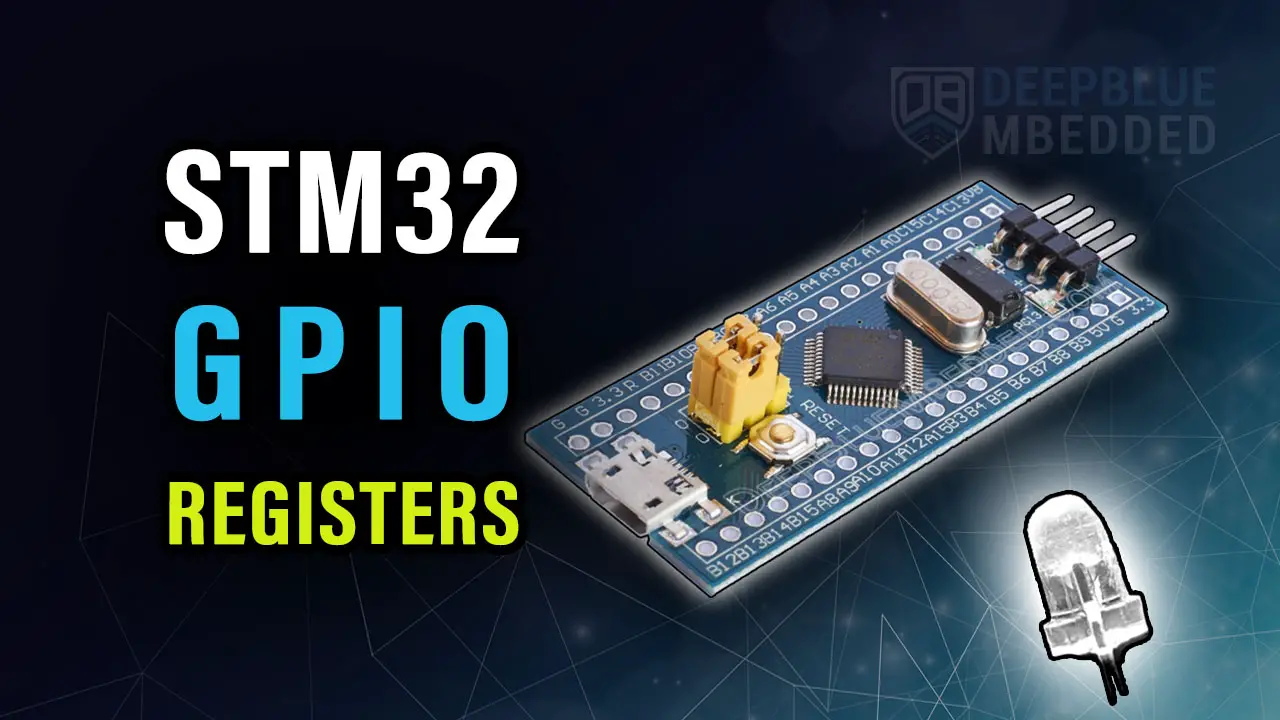
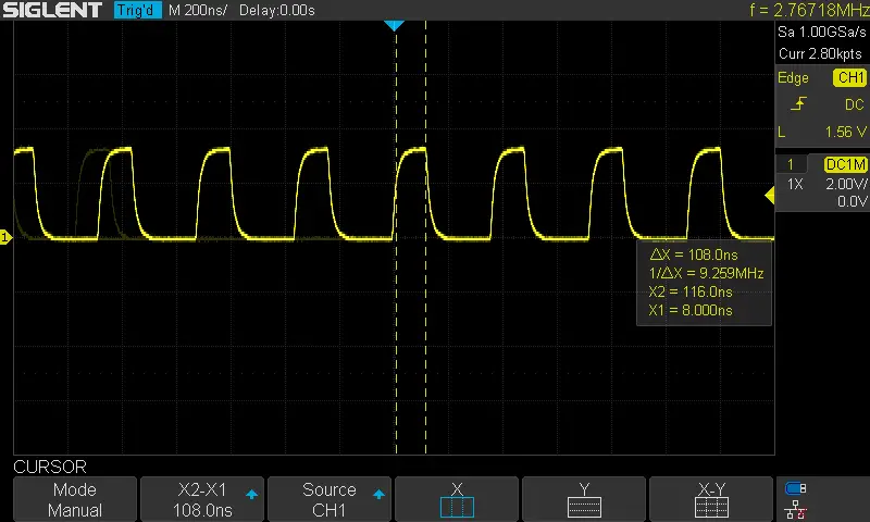
GPIO Register Macros Vs HAL (Speed Test)
Let’s now test and compare the performance of the GPIO register access macros against the standard HAL GPIO pin control APIs (functions).
| Register Macros | HAL | ||||
|
|
||||
 |
 |
||||
| 110ns | 650ns |
As you’ve seen the result shows a significant improvement in the GPIO pin set/clear operations compared to the HAL function. This is very useful for a lot of GPIO-based measurements and also if you need to optimize operations inside an ISR, you can replace HAL_GPIO_WritePin with the shown macro definitions to save up to 0.5µs.
Required Parts For STM32 Examples
All the example Code/LABs/Projects in this STM32 Series of Tutorials are done using the Dev boards & Electronic Parts Below:
| QTY. | Component Name | Amazon.com | AliExpress | eBay |
| 1 | STM32-F103 BluePill Board (ARM Cortex-M3 @ 72MHz) | Amazon | AliExpress | eBay |
| 1 | Nucleo-L432KC (ARM Cortex-M4 @ 80MHz) | Amazon | AliExpress | eBay |
| 1 | ST-Link V2 Debugger | Amazon | AliExpress | eBay |
| 2 | BreadBoard | Amazon | AliExpress | eBay |
| 1 | LEDs Kit | Amazon & Amazon | AliExpress | eBay |
| 1 | Resistors Kit | Amazon & Amazon | AliExpress | eBay |
| 1 | Capacitors Kit | Amazon & Amazon | AliExpress & AliExpress | eBay & eBay |
| 1 | Jumper Wires Pack | Amazon & Amazon | AliExpress & AliExpress | eBay & eBay |
| 1 | Push Buttons | Amazon & Amazon | AliExpress | eBay |
| 1 | Potentiometers | Amazon | AliExpress | eBay |
| 1 | Micro USB Cable | Amazon | AliExpress | eBay |
★ Check The Links Below For The Full Course Kit List & LAB Test Equipment Required For Debugging ★
Download Attachments
You can download all attachment files for this Article/Tutorial (project files, schematics, code, etc..) using the link below. Please consider supporting our work through the various support options listed in the link down below. Every small donation helps to keep this website up and running and ultimately supports the whole community.
Wrap Up
In conclusion, it was quite easy to use the STM32 GPIO registers to configure input & output pins, read & write digital pins, and perform direct register access to control individual pins or whole ports. The register macro definitions illustrated in this tutorial will be used in later STM32 tutorials & projects, so make sure you try the provided examples on your own to get the hang of it.
If you’re just getting started with STM32, you need to check out the STM32 Getting Started Tutorial here.
Follow this STM32 Series of Tutorials to learn more about STM32 Microcontrollers Programming.
GPIOB->CRL |= GPIO_CRL_MODE0; // Set Pin B0 As Output With High-Frequency Speed (Mode0[1:0]=11)
Wouldn’t that only set one bit and the mode would be 01 rather than 11?