In this tutorial, we’ll discuss the STM32 ADC Multi-Channel Scan Continuous Conversion Mode with DMA for reading the ADC conversion results of a regular group of channels. You’ll learn how STM32 ADC Multi-Channel Scan mode works and how to use it to read a regular group of multiple ADC channels and get the conversion data using DMA with the STM32 HAL API functions.
The practical example we’ll implement in this tutorial is an STM32 LED dimmer using multiple potentiometers on multiple analog input pins and multiple PWM outputs to control the brightness of some LEDs. We’ll read the multiple analog input channels (regular group) in continuous-conversion mode using the DMA. Without further ado, let’s get right into it!
Table of Contents
- STM32 ADC Multi-Channel Scan (Continuous-Conversion)
- STM32 ADC Multi-Channel Continuous Mode Example
- STM32 ADC Multi-Channel Scan Continuous Mode DMA Example
- STM32 ADC Multi-Channel Scan (Continuous-Conversion) Polling
- STM32 ADC Multi-Channel Scan (Continuous-Conversion) Interrupt
- Wrap Up
STM32 ADC Multi-Channel Scan (Continuous-Conversion)
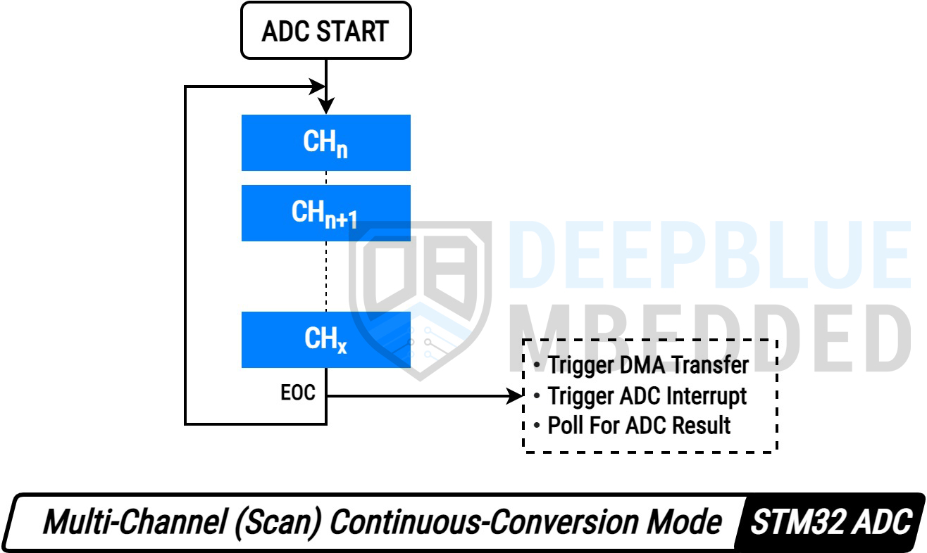
In this tutorial, we’ll explore the STM32 ADC Multi-Channel Scan Mode in continuous-conversion mode. In this mode, the ADC will start converting the configured regular group of channels one by one according to the channel ranks (from low to high) till the end of the group where it stops and generates an interrupt signal indicating the end of the regular group’s conversion process.
The ADC will then “automatically” restart/re-trigger itself to start converting the regular group channels one by one again and keep repeating forever. This is unlike the Multi-Channel Scan Single-Conversion Mode that we’ve discussed in a previous tutorial. Where the ADC stops at the end of the regular group conversion and it needs to be “manually” started again.
The STM32 ADC Multi-Channel Scan Continuous Mode can only be used with DMA to get the ADC reading results as soon as the group conversion is completed. And that’s what we’ll do in the practical example project hereafter in this tutorial.
1. STM32 ADC Multi-Channel Polling (Continuous Conversion)
Can we use Polling with STM32 ADC Multi-Channel Scan in Continuous-Conversion Mode? The answer is NO. The polling can only be used with the ADC Multi-Channel Scan in Discontinuous Mode, Refer to this tutorial & example project for more details.
Therefore, it’s impractical and near impossible to implement a polling-based software or state machine to read the ADC scan (regular group) conversions in the continuous-conversion mode.
2. STM32 ADC Multi-Channel Interrupt (Continuous Conversion)
Using interrupts with ADC Multi-Channel scan mode is just impossible as stated in the documentation of the STM32 microcontroller’s datasheet. Because the interrupt signal is fired at the end of the regular group conversion. Whether it’s a single-conversion or continuous-conversion mode, it won’t work.
In other words, the ADC result buffer will keep getting overwritten by the regular group channels one by one from the lowest rank to the highest. At the time of interrupt firing, you’ll only find the last group’s channel reading in the ADC buffer and all the previous channels are gone forever.
3. STM32 ADC Multi-Channel DMA (Continuous Conversion)
And here comes the third method which is using the DMA unit that can directly transfer the ADC result from the peripheral to the memory in the manner that you want and program it to. All that is done without any CPU intervention and upon DMA transfer completion, it can notify the CPU to process the data or whatever.
To sum things up, the STM32 ADC in Multi-Channel Scan Mode (Continuous-Conversion) can only be reliably used with DMA. The interrupt-based reading is impossible to implement and the polling method can potentially cause your system to fail (halt forever) or get the channels’ readings mixed up no matter how hard you try to build a perfect state machine to capture the readings at the right time.
STM32 ADC Multi-Channel Continuous Mode Example
In this example project, we’ll create an STM32 LED Dimmer using ADC & PWM to read multiple analog inputs from 4x potentiometers to control the brightness of 4x PWM outputs going to 4x LEDs. This demo will run the STM32 ADC in multi-channel continuous-conversion mode using DMA.
- Set up a new project as usual with system clock @ 72MHz
- Set up 4x Analog Input Pins (Channel 6, 7, 8, and 9) In Continuous-Conversion Mode (The 4x Pot. Pin)
- Set up Timer2 in PWM mode with output on channels 1-4 (The 4x LED Pins)
STM32 ADC Multi-Channel Scan Continuous Mode DMA Example
In this LAB, our goal is to build a system that initializes multiple ADC analog input pins (4x channels: 6-9). And also configure a timer module to operate in PWM mode with 4x outputs on channels 1-4 (4x LED pins). Therefore, we can start an ADC regular group conversion, get & map the results to the PWM duty cycle registers, and repeat the whole process over and over again.
And now, let’s build this system step-by-step
Step #1
Open STM32CubeMX, create a new project, and select the target microcontroller.
Step #2
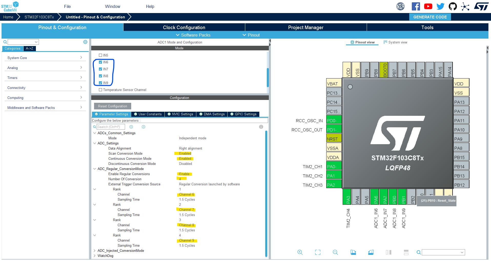
Configure The ADC1 Peripheral, Enable the Channels: 6-9, and enable the continuous mode. You’ll find that the analog channel has these default configurations which happens to be ok for us in this example project.
Step #3
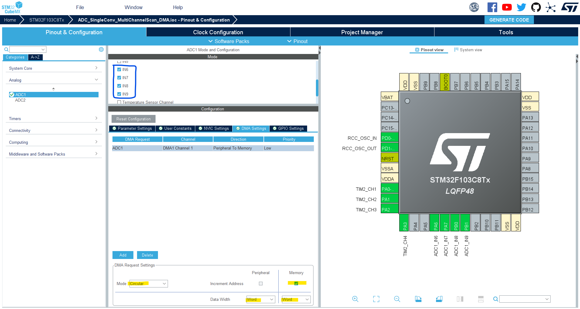
The DMA interrupt is enabled by default in the NVIC controller tab. The STM32 DMA configurations for the ADC will be as shown below.
Step #4
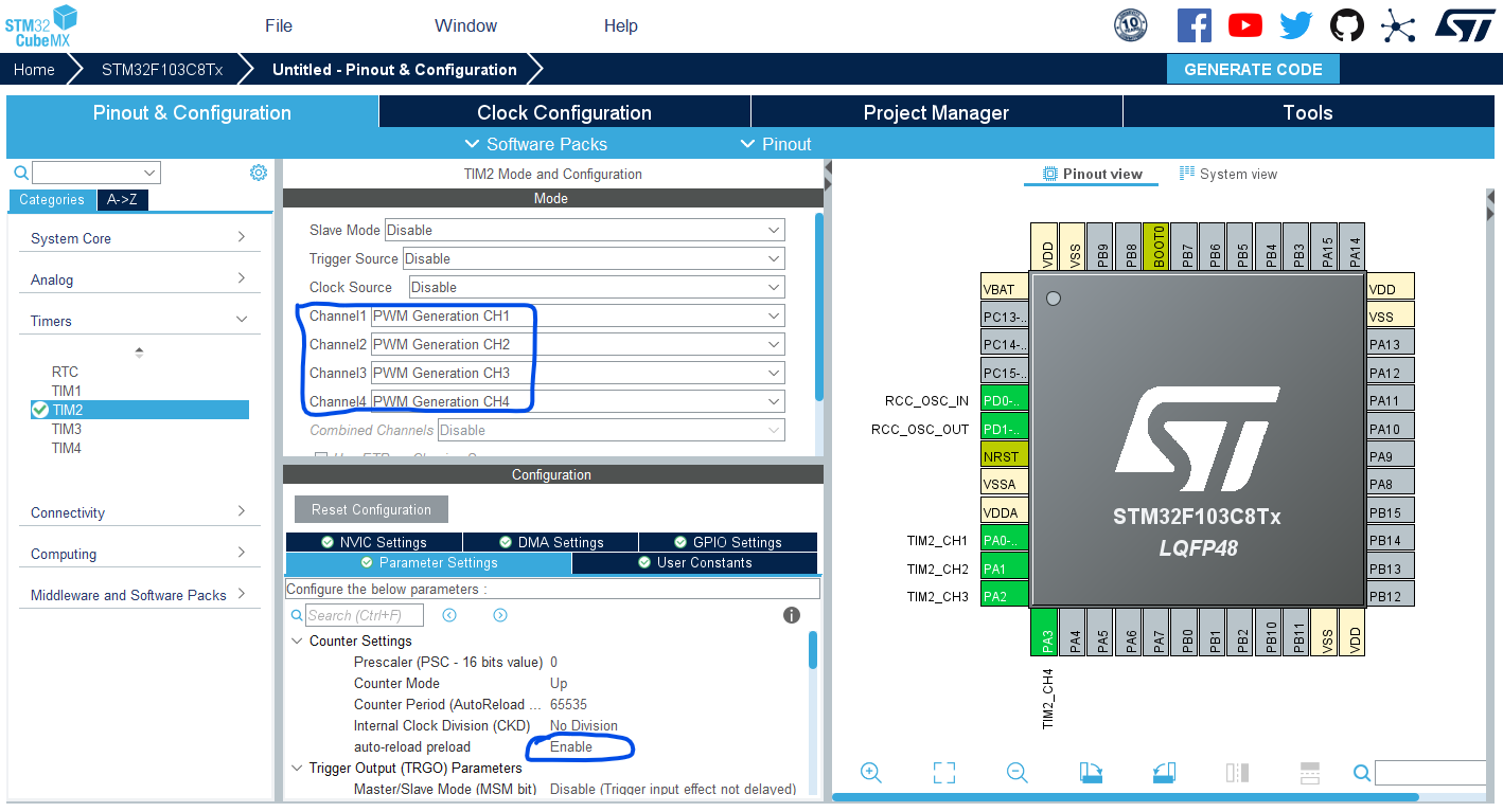
Configure Timer2 To Operate In PWM Mode With Output On CH1-4.
Step #5
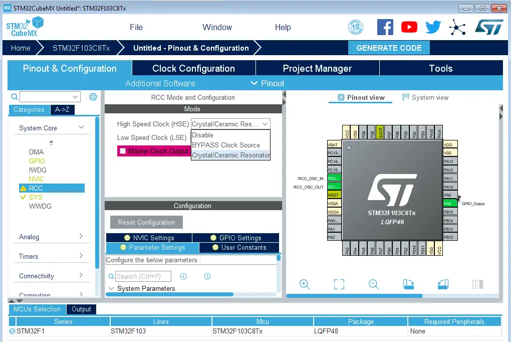
Go to the RCC clock configuration page and enable the HSE external crystal oscillator input.
Step #6
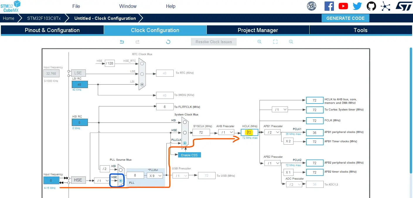
Go to the clock configurations page, and select the HSE as a clock source, PLL output, and type in 72MHz for the desired output system frequency. Hit the “ Enter” key, and let the application solve for the required PLL dividers/multipliers to achieve the desired clock rate.
Step #7
Name & Generate The Project Initialization Code For CubeIDE or The IDE You’re Using.
STM32 ADC Multi-Channel Scan Continuous-Conversion (DMA) Example Code
Here is The Application Code For This LAB (main.c)
|
1 2 3 4 5 6 7 8 9 10 11 12 13 14 15 16 17 18 19 20 21 22 23 24 25 26 27 28 29 30 31 32 33 34 35 36 37 38 39 40 41 42 43 44 45 46 47 48 |
/* * LAB Name: STM32 ADC Multi-Channel (Scan) Continuous-Conversion Mode - DMA * Author: Khaled Magdy * For More Info Visit: www.DeepBlueMbedded.com */ #include "main.h" uint32_t AD_RES_BUFFER[4]; ADC_HandleTypeDef hadc1; DMA_HandleTypeDef hdma_adc1; TIM_HandleTypeDef htim2; void SystemClock_Config(void); static void MX_GPIO_Init(void); static void MX_DMA_Init(void); static void MX_ADC1_Init(void); static void MX_TIM2_Init(void); int main(void) { HAL_Init(); SystemClock_Config(); MX_GPIO_Init(); MX_DMA_Init(); MX_ADC1_Init(); MX_TIM2_Init(); HAL_TIM_PWM_Start(&htim2, TIM_CHANNEL_1); HAL_TIM_PWM_Start(&htim2, TIM_CHANNEL_2); HAL_TIM_PWM_Start(&htim2, TIM_CHANNEL_3); HAL_TIM_PWM_Start(&htim2, TIM_CHANNEL_4); HAL_ADC_Start_DMA(&hadc1, AD_RES_BUFFER, 4); while (1) { // Nothing To Do! } } void HAL_ADC_ConvCpltCallback(ADC_HandleTypeDef* hadc) { // Conversion Complete & DMA Transfer Complete As Well // So The AD_RES_BUFFER Is Now Updated & Let's Move Values To The PWM CCRx // Update The PWM Channels With Latest ADC Scan Conversion Results TIM2->CCR1 = (AD_RES_BUFFER[0] << 4); // ADC CH6 -> PWM CH1 TIM2->CCR2 = (AD_RES_BUFFER[1] << 4); // ADC CH7 -> PWM CH2 TIM2->CCR3 = (AD_RES_BUFFER[2] << 4); // ADC CH8 -> PWM CH3 TIM2->CCR4 = (AD_RES_BUFFER[3] << 4); // ADC CH9 -> PWM CH4 } |
ADC Multi-Channel DMA Code Explanation
We only trigger the ADC once to start conversion in DMA mode. As it’s running in the continuous-conversion mode, it’ll keep triggering itself after the completion of the regular group conversion and we don’t need to “manually” start/trigger the ADC again.
Upon DMA transfer completion, the DMA interrupt is fired. In its ISR, we read the ADC_RES_BUFFER array to get the readings of the ADC Channels (6-9). Then we map those readings from 12-bit to 16-bit values to be written to the timer’s CCRx registers for PWM duty cycle control.
Using the DMA is the best way to read the STM32 ADC in multi-channel (scan) mode whether it’s a single-conversion (one-shot) or a continuous-conversion mode.
Wiring
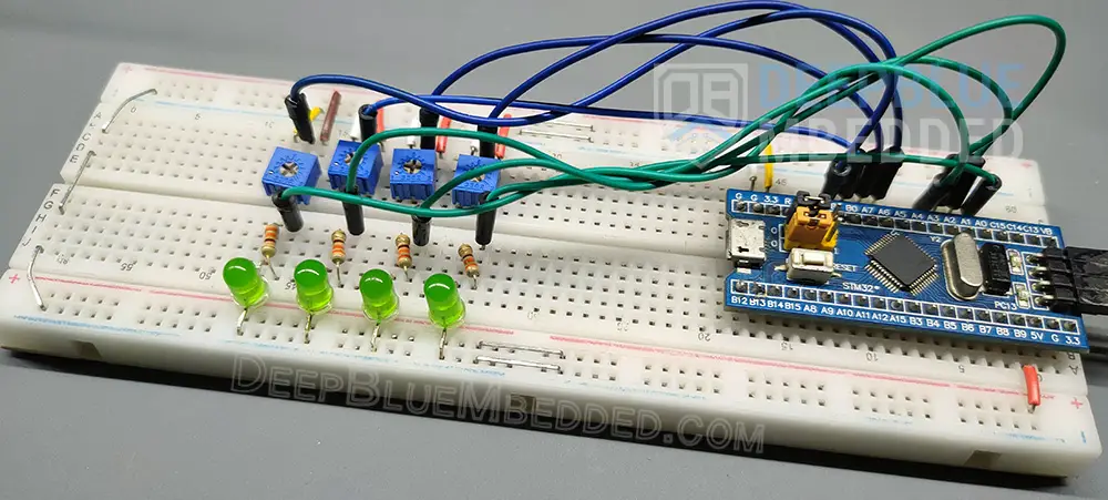
I know it looks messy, but there isn’t too much about it. These are only 4x LEDs and 4x potentiometers connected to the corresponding GPIO pins on the STM32 blue pill board.
STM32 ADC Multi-Channel Continuous-Conversion DMA Example Testing
In this example demo, I’ve enabled the DMA interrupt to give you a hint of how it can be incorporated into the final application. However, I’d advise against using it in this application as it, unnecessarily, adds so much CPU load. You’d be better off disabling the DMA interrupt and using the global AD_RES_BUFFER buffer to read the last ADC result and map that to the PWM duty cycle. Which can be done in the main while(1) loop, in a periodic timer-based interrupt, or anywhere else.
To enable the DMA interrupt, you need to have a sufficiently large buffer so the DMA interrupts are less frequent to keep the system as efficient as possible. As long as the data is not urgently needed for real-time processing, things can be asynchronously accessed in a periodic way to keep the system’s dynamic behavior as predictable as possible.
STM32 ADC Multi-Channel Scan (Continuous-Conversion) Polling
This application is almost impossible to build and even if we did, it’ll still be impractical as the CPU will most probably miss reading the ADC channel before it’s overwritten by the next conversion. This could have been done if we were working in the Multi-Channel Scan Disontinuous-Mode, however, in the continuous conversion mode we’re not able to activate the discontinuous conversion and we won’t be able to implement such a thing.
STM32 ADC Multi-Channel Scan (Continuous-Conversion) Interrupt
This application is also impossible to build as stated in the STM32 ADC documentation (reference manual). We used to build this interrupt-based application for all the previous STM32 ADC tutorial parts, however, we won’t be doing it this time.
For ADC Multi-Channel regular group scan, reading the conversion can either be achieved by Polling ( HAL_ADC_Start() with Discontinuous mode and NbrOfDiscConversion=1) or by DMA ( HAL_ADC_Start_DMA()), but not by interruption ( HAL_ADC_Start_IT()).
In the STM32 ADC multi-channel scan mode, interruption is triggered only on the last conversion of the sequence. All previous conversions will be overwritten by the last one. The injected group used with scan mode doesn’t have this limitation. Each rank has its own result buffer register, no data is overwritten in injected mode as we’ll test it in a later tutorial in this multi-part STM32 ADC series.
To sum things up, we just can’t use the interrupt with the STM32 ADC in scan mode (multi-channel) conversion. The interrupt is fired only on the last conversion of the sequence (regular group of channels). All previous conversions will be overwritten by the last one.
Required Parts For STM32 Examples
All the example Code/LABs/Projects in this STM32 Series of Tutorials are done using the Dev boards & Electronic Parts Below:
| QTY. | Component Name | Amazon.com | AliExpress | eBay |
| 1 | STM32-F103 BluePill Board (ARM Cortex-M3 @ 72MHz) | Amazon | AliExpress | eBay |
| 1 | Nucleo-L432KC (ARM Cortex-M4 @ 80MHz) | Amazon | AliExpress | eBay |
| 1 | ST-Link V2 Debugger | Amazon | AliExpress | eBay |
| 2 | BreadBoard | Amazon | AliExpress | eBay |
| 1 | LEDs Kit | Amazon & Amazon | AliExpress | eBay |
| 1 | Resistors Kit | Amazon & Amazon | AliExpress | eBay |
| 1 | Capacitors Kit | Amazon & Amazon | AliExpress & AliExpress | eBay & eBay |
| 1 | Jumper Wires Pack | Amazon & Amazon | AliExpress & AliExpress | eBay & eBay |
| 1 | Push Buttons | Amazon & Amazon | AliExpress | eBay |
| 1 | Potentiometers | Amazon | AliExpress | eBay |
| 1 | Micro USB Cable | Amazon | AliExpress | eBay |
★ Check The Links Below For The Full Course Kit List & LAB Test Equipment Required For Debugging ★
Download Attachments
You can download all attachment files for this Article/Tutorial (project files, schematics, code, etc..) using the link below. Please consider supporting our work through the various support options listed in the link down below. Every small donation helps to keep this website up and running and ultimately supports the whole community.
Wrap Up
In conclusion, we’ve explored how to read the STM32 ADC multiple-channel in continuous-conversion mode using the DMA. Be advised that you can’t use the interrupt or polling methods with the ADC in multi-channel scan continuous-conversion mode. The DMA is the only viable option for this sort of application.
You can build on top of the examples provided in this tutorial and/or explore the other parts of the STM32 ADC tutorials series for more information about the other STM32 ADC operating modes and conversion schemes.
