| Previous Tutorial | Tutorial 25 | Next Tutorial | |||||
| Interfacing 16×2 LCD With PIC Microcontrollers | |||||||
| Intermediate Level ★★☆☆☆ | |||||||
In this tutorial, we’ll discuss how Alphanumeric LCD works and how to interface a 16×2 LCD with a microcontroller. You’ll learn how LCD (Liquid Crystal Display) works internally and how to send data and commands to it with a microcontroller, specifically PIC MCUs. And you’ll also learn how to develop a simple LCD Driver for your upcoming projects.
There are 2 practical LABs associated with this tutorial and here is a brief animation indicating what you’ll be able to do after completing this tutorial.
[toc]
Required Components For This Tutorial
| Qty. | Component Name | Buy On Amazon.com |
| 1 | PIC16F877A
or PIC18F2550 |
Add |
| 1 | BreadBoard | Add |
| 1 | Alphanumeric LCD 16×2 | Add |
| 1 | Jumper Wires Pack | Add Add |
| 1 | LM7805 Voltage Regulator (5v) | Add |
| 1 | 8MHz Crystal Oscillator | Add |
| 1 | PICkit2 or 3 Programmer | Add |
16×2 LCD Module
We typically add a 16×2 Alphanumeric LCD to small embedded systems & projects to enhance the user experience and UI of the device/project. You can use it to display text messages to the user, number, etc. Other types of LCDs provide different features such as the number of columns and rows (characters) and maybe colored display, and also different interfaces (parallel, spi, i2c, etc).
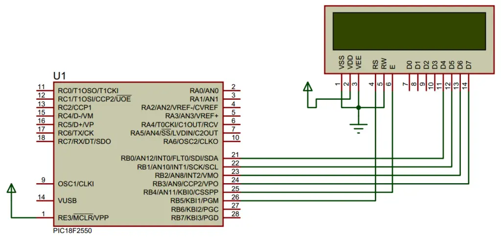
For this tutorial, we’ll consider the 16×2 LCD with a 16-pin header interface. Assuming it has the standard Hitachi LCD driver HD44780 controller. We’ll see how it works internally and how to interface it with microcontrollers. This small IC on the backside of the LCD module controls the LCD itself and accepts user commands and data sent by the master MCU.
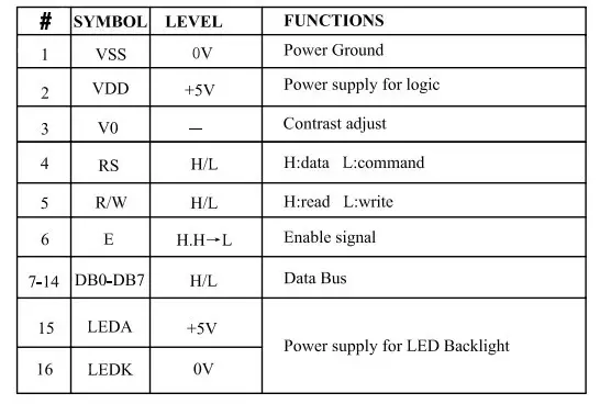
LCD Module Pinout
This is the pinout for a typical LCD 16×2 display unit.
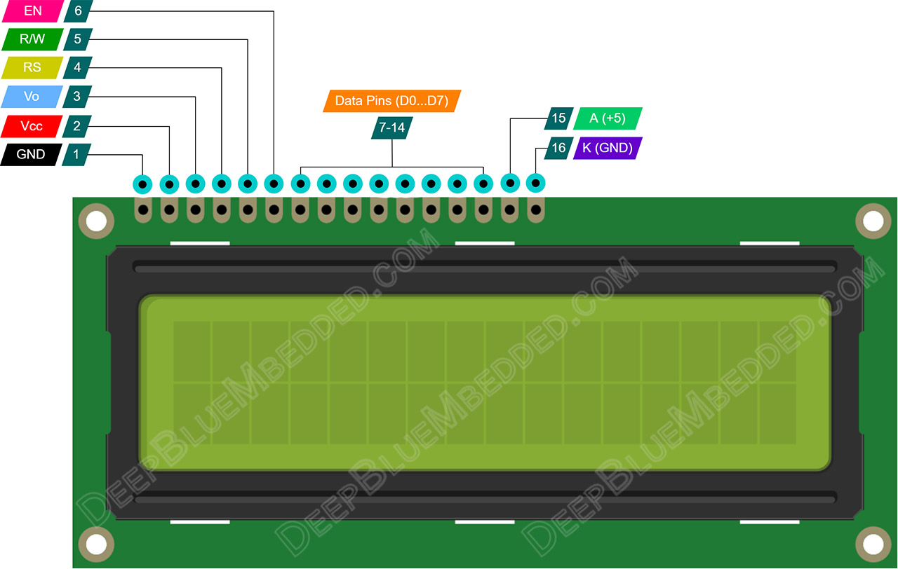
Pins’ Functions Description
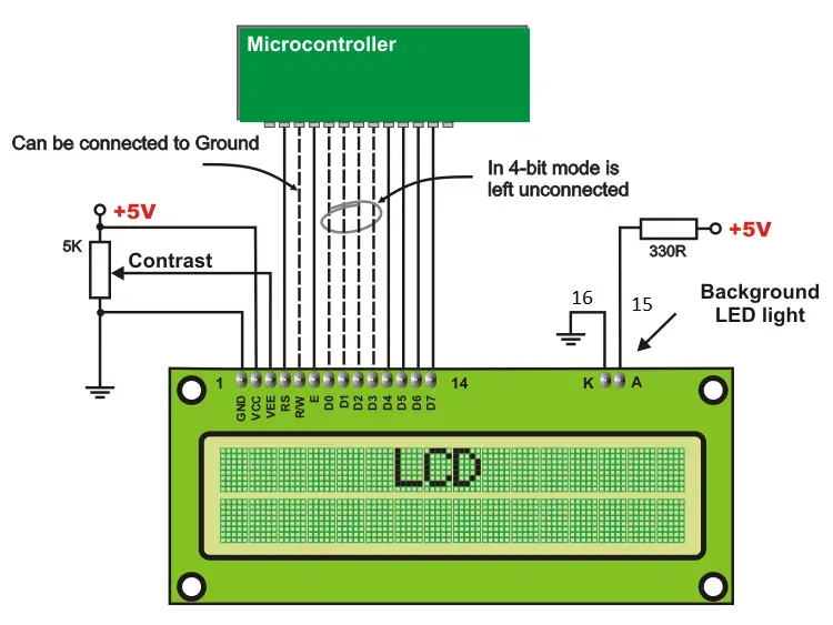
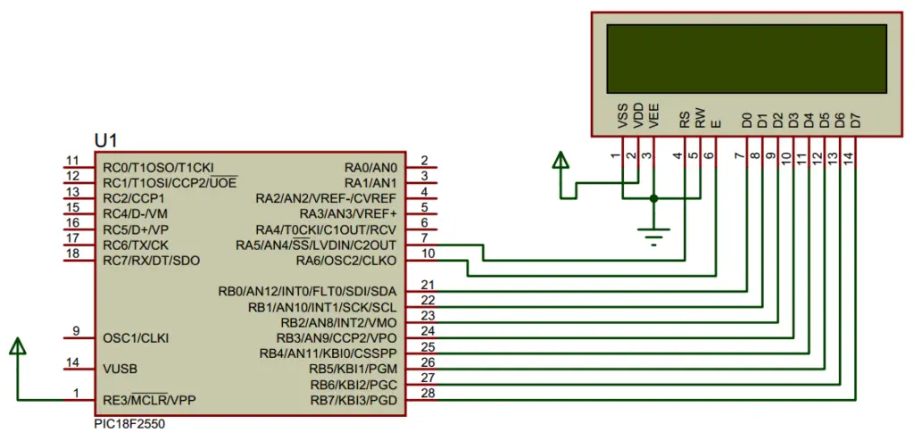
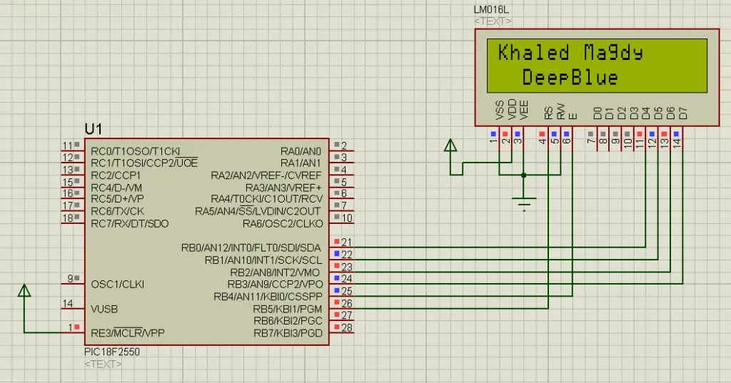
LCD Connection Diagram With MCU
LCD Controller IC
The LCD module consists of 16×2 character cells, and each one of them is 5×8 dots. Controlling all of this is a tedious task for our main microcontroller to do. However, it doesn’t have to do. As there is a specific function controller on the LCD itself controlling the display while reading in the user’s commands & data. Here, I’ll be considering the Hitachi HD44780 controller.
LCD Driver Block Diagram
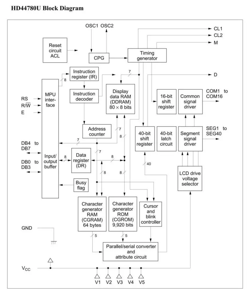
Internal Registers (IR & DR)
The HD44780U has two 8-bit registers, an instruction register (IR) and a data register (DR). The IR stores instruction codes, such as display clear and cursor shift, and address information for display data RAM (DDRAM) and character generator RAM (CGRAM). The IR can only be written from the MPU. The DR temporarily stores data to be written into DDRAM or CGRAM and temporarily stores data to be read from DDRAM or CGRAM. Data written into the DR from the MPU is automatically written into DDRAM or CGRAM by an internal operation.
Display Data RAM (DDRAM)
Display data RAM (DDRAM) stores display data represented in 8-bit character codes. Its extended capacity is 80 × 8 bits, or 80 characters. The area in display data RAM (DDRAM) that is not used for display can be used as general data RAM. Therefore, whatever data you send to the DDRAM, it’ll get displayed on the LCD. As long as the characters count is below 32 (for 16×2 LCD), it’ll be visible. Otherwise, written characters are stored in the DDRAM but not visible.
Character Generator ROM (CGROM)
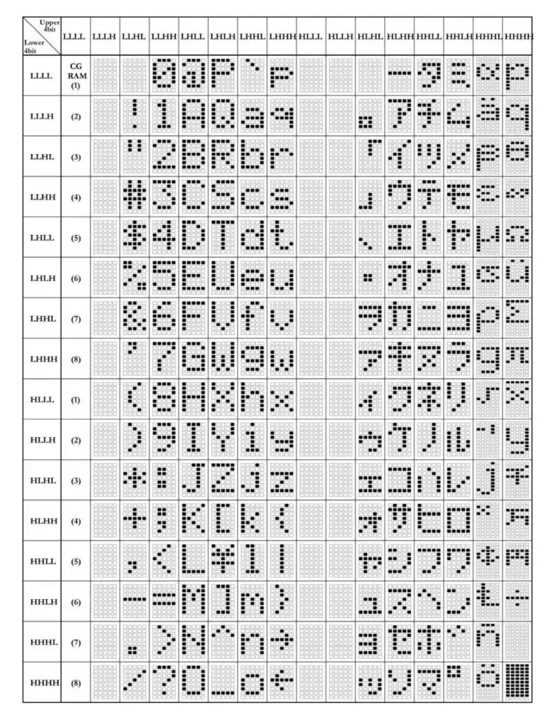
The character generator ROM generates 5 × 8 dots or 5 × 10 dot character patterns from 8-bit character codes. It can generate 208 5 × 8 dot character patterns and 32 5 × 10 dot character patterns. User-defined character patterns are also available by mask-programmed ROM.
The table down below shows you the standard ASCII equivalent characters for the LCD display stored in the CGROM. And you can also create your custom characters and symbols if you want to, as we’ll see in a future tutorial. Note the “A” character which has a binary code of (0100 0001)b this is equivalent to 65 (the ASCII value for A in the ASCII table).
Character Generator RAM (CGRAM)
In the character generator RAM, the user can rewrite character patterns by the program. For 5 × 8 dots, eight-character patterns can be written, and for 5 × 10 dots, four-character patterns can be written. Write into DDRAM the character codes at the addresses shown as the left column of the above table to show the character patterns stored in CGROM.
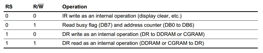
Busy Flag (BF)
When the busy flag is 1, the HD44780U is in the internal operation mode, and the next instruction will not be accepted. When RS = 0 and R/W = 1, the busy flag is output to DB7. The next instruction must be written after ensuring that the busy flag is 0.
Address Counter (AC)
The address counter (AC) assigns addresses to both DDRAM and CGRAM. When an address of an instruction is written into the IR, the address information is sent from the IR to the AC. Selection of either DDRAM or CGRAM is also determined concurrently by the instruction. After writing into (reading from) DDRAM or CGRAM, the AC is automatically incremented by 1 (decremented by 1). The AC contents are then output to DB0 to DB6 when RS = 0 and R/W = 1.
LCD Register Selection
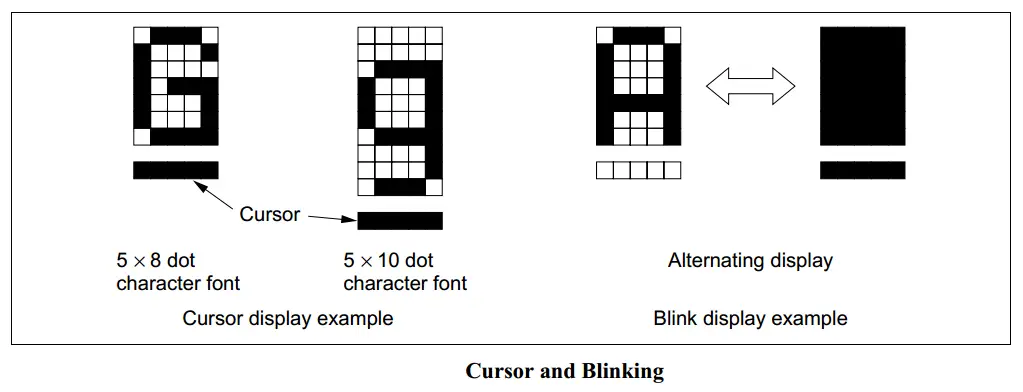
Cursor/Blink Control Circuit
The cursor/blink control circuit generates the cursor or character blinking. The cursor or the blinking will appear with the digit located at the display data RAM (DDRAM) address set in the address counter (AC).
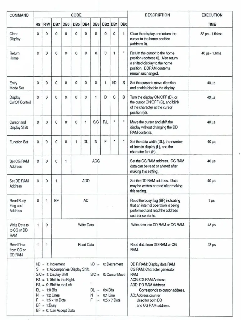
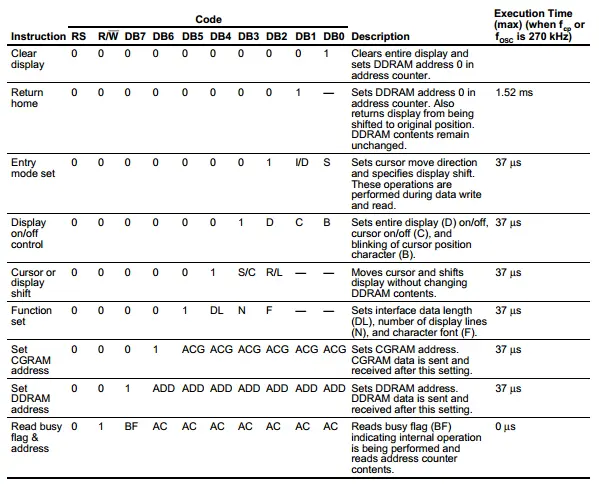
LCD Driver Instructions Table
16×2 LCD Interfaces
There are two ways to interface the LCD diver (controller) IC. You can use the full bus width (8-Bits) for data or alternatively you can use a 4-Bit interface for a reduced pin count needed to control the LCD. Specifically low pin count MCUs need to operate in the 4-Bit mode.
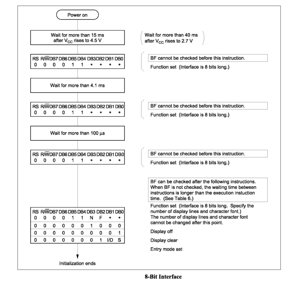
8-Bit Interface
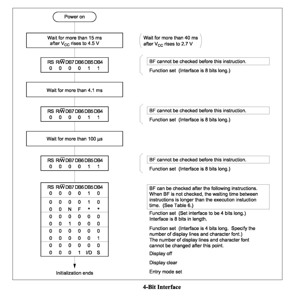
4-Bit Interface
How To Setup & Write To LCD
1. LCD Initialization
At the beginning of your system’s firmware, you should do some initialization steps for the LCD display before it’s usable. These steps are listed by the manufacturer of the LCD Driver IC and let your LCD know how it’s going to operate afterward. Which interface mode you’ll be using (4 or 8 bits), which font and so on.
8-Bit Interface
Down below are the exact steps to initialize the LCD module for 8-Bit line interface.
4-Bit Interface
Down below are the exact steps to initialize the LCD module for 4-Bit line interface.
2. Reading The Busy Flag
The LCD takes some time to process commands or data. Therefore, there must be a small delay before issuing a new command to the LCD. This delay could be chosen arbitrarily as long as it’s longer than the time required by the LCD itself as indicated in the datasheet. Alternatively, you can just read the busy flag bit to know whether the previous command was successfully processed or not.
When a data or a command is sent to the LCD, the BF or D7 bit of the LCD becomes 1 and as soon as the command is successfully processed, the BF becomes 0.
Steps To Read The Busy Flag (BF)
Down below are the exact steps to read the busy flag bit.
- Select Command Register
- Select Read Operation
- Send Enable Signal
- Read The Flag (D7 pin)
3. Sending Commands To LCD
To send commands, we’ll need to select the command register and transfer the corresponding bits as we’ve done previously in the initialization step. Here are the exact steps to follow
- Move The Data To The Output Port (LCD Pins)
- Select The Command Register
- Select Write Operation
- Send Enable Signal
- Wait For LCD To Process The Command
And below is another version of the instructions table as found in the datasheet. We may not implement all of them in this tutorial, so it’s a good idea to download the datasheet and have a look on these instructions (commands) as you may need one or more of them in your projects.
And here is another table for some commands examples that you can test yourself. We’ll implement a couple of them in the following practical LABs and the rest are left for you to experiment with.
Implementing a PIC LCD Driver Library
1 Creating IO Pin Map Definitions
First of all, we should define the IO pins which we’ll be using to interface the LCD. It’s a recommended practice to isolate the hardware drivers firmware from the application layer and for the sake of portability of your code. This step makes your code less dependent on the specific MCU chip you’re using in the current project.
Here are the IO pins we’ll need for LCD interfacing and this is how to define them.
|
1 2 3 4 5 6 7 8 9 |
#define LCD_DATA_PORT_D TRISB #define LCD_RS_D TRISB5 #define LCD_EN_D TRISB4 #define RS RB5 #define EN RB4 #define D4 RB0 #define D5 RB1 #define D6 RB2 #define D7 RB3 |
if at any point you found out that a specific pin must be changed, it’ll be an easy task to change it without searching your code and replacing each and every single occurrence for that line of code.
2 Sending Data To The LCD
We’ll be using the 4-Bit interface in these tutorials as it’s the most common and most wished for. Nobody wants to consume all of his microcontroller’s pins just to hook an LCD. In fact, there is an I2C interface for the LCD which we’ll be using in a future tutorial and its main feature is reducing the pin count used for LCD control.
All in all, what we need now is a routine to parse out half-a-byte of data and send these bits to the corresponding pins of the IO pins associated with LCD Data. Here is a simple implementation for such a routine.
|
1 2 3 4 5 6 7 8 9 10 11 12 13 14 15 16 17 18 19 |
void LCD_DATA(unsigned char Data) { if(Data & 1) D4 = 1; else D4 = 0; if(Data & 2) D5 = 1; else D5 = 0; if(Data & 4) D6 = 1; else D6 = 0; if(Data & 8) D7 = 1; else D7 = 0; } |
3 Sending Commands To The LCD
As we’ve discussed earlier in this tutorial, sending a command to the LCD should start with selecting the command register. Then the command data is transferred to the LCD io data pins. Then we should clock or send enable signal pulse. This routine is followed in general settings, whether it’s a 4-Bit interface of an 8-Bit.
For our case, using a 4-Bit interface, sending an 8-Bit command will be done in 2 exact steps. Hence, we’ll be using the same routine but twice instead of once.
|
1 2 3 4 5 6 7 8 9 10 11 |
void LCD_CMD(unsigned char CMD) { // Select Command Register RS = 0; // Move The Command Data To LCD LCD_DATA(CMD); // Send The EN Clock Signal EN = 1; __delay_us(LCD_EN_Delay); EN = 0; } |
4 Initializing The LCD Module
Now, it’s time to create the LCD initialization routine. This function is an exact implementation of the steps we’ve discussed earlier in this tutorial. The 4-Bit interface initialization steps are indicated in a previous flow chart and our task right now is to implement it in C.
|
Initialization Procedure In Datasheet
|
5 Writing A Character To The LCD
Sending an 8-Bit character to the LCD followed by an enable pulse (clock) will display that character on the LCD. However, in our case of using a 4-Bit interface, this step will be divided into two consequent steps. First of which is parsing the 8-Bit character into a high_nibble and low_nibble. Then we’ll send the high4 bits first followed by an EN clock, then we’ll send the low4 bits followed by another EN clock. And that’s it!
|
1 2 3 4 5 6 7 8 9 10 11 12 13 14 15 16 17 |
void LCD_Write_Char(char Data) { char Low4,High4; Low4 = Data & 0x0F; High4 = Data & 0xF0; RS = 1; LCD_DATA(High4>>4); EN = 1; __delay_us(LCD_EN_Delay); EN = 0; __delay_us(LCD_EN_Delay); LCD_DATA(Low4); EN = 1; __delay_us(LCD_EN_Delay); EN = 0; __delay_us(LCD_EN_Delay); } |
6 Writing Text To The LCD
To send a string to the LCD, we’ll need a loop to repeatedly send characters to the LCD until a buffer end is found, and typically it’s the NULL character “\0”. Here is the implementation of this routine.
|
1 2 3 4 5 6 |
void LCD_Write_String(char *str) { int i; for(i=0;str[i]!='\0';i++) LCD_Write_Char(str[i]); } |
Adding Auxiliary Functions To PIC LCD Library
As you’ve seen in the previous sections, the datasheet of the LCD driver IC includes all the command that it could handle. And we’re going to add a couple of them to our LCD Driver code. All the rest are left for you to experiment with. Some specific commands may help you in specific projects and it’s up to you to decide on which one you need to implement.
The commands I’m going to implement in this section are the most used ones in different projects. And will help you get more familiar with sending commands in 4-Bit mode. And there is no difference from what we’ve done so far.
LCD Clear
![]()
|
1 2 3 4 5 |
void LCD_Clear() { LCD_CMD(0); LCD_CMD(1); } |
Set LCD Cursor Position
![]()
r -> row number, c -> column number. And the cursor position offset is calculated from the base 0x80
|
1 2 3 4 5 6 7 8 9 10 11 12 13 14 15 16 17 18 19 20 |
void LCD_Set_Cursor(unsigned char r, unsigned char c) { unsigned char Temp,Low4,High4; if(r == 1) { Temp = 0x80 + c - 1; //0x80 is used to move the cursor High4 = Temp >> 4; Low4 = Temp & 0x0F; LCD_CMD(High4); LCD_CMD(Low4); } if(r == 2) { Temp = 0xC0 + c - 1; High4 = Temp >> 4; Low4 = Temp & 0x0F; LCD_CMD(High4); LCD_CMD(Low4); } } |
Shift Entire Display Right
![]()
|
1 2 3 4 5 |
void LCD_SR() { LCD_CMD(0x01); LCD_CMD(0x0C); } |
Shift Entire Display Left
![]()
|
1 2 3 4 5 |
void LCD_SL() { LCD_CMD(0x01); LCD_CMD(0x08); } |
PIC LCD Library Example Code
As we’ve pointed out earlier, it’s a better practice to separate the hardware drivers code from the main application layer. This increases your code portability, re-usability and reduces the overhead of debugging a single 1k line of code main.c file. Apply this to all the drivers we’ve built so far (UART, SPI, PWM, etc.)
1 Create LCD.h Header File
The header file includes only the declarations of sub-routines with simple documentation indicating the functionality of each routine and what it takes and returns if it’s not void, etc. The LCD.h header file will be something like this
|
1 2 3 4 5 6 7 8 9 10 11 12 13 14 15 16 17 18 19 20 21 22 23 24 25 26 27 28 |
#include <xc.h> #define _XTAL_FREQ 48000000 #define LCD_EN_Delay 500 #define LCD_DATA_PORT_D TRISB #define LCD_RS_D TRISB5 #define LCD_EN_D TRISB4 #define RS RB5 #define EN RB4 #define D4 RB0 #define D5 RB1 #define D6 RB2 #define D7 RB3 //============================================== //-----[ Prototypes For All LCD Functions ]----- void LCD_Init(); // Initialize The LCD For 4-Bit Interface void LCD_Clear(); // Clear The LCD Display void LCD_SL(); // Shift The Entire Display To The Left void LCD_SR(); // Shift The Entire Display To The Right void LCD_CMD(unsigned char); // Send Command To LCD void LCD_DATA(unsigned char); // Send 4-Bit Data To LCD void LCD_Set_Cursor(unsigned char, unsigned char); // Set Cursor Position void LCD_Write_Char(char); // Write Character To LCD At Current Position void LCD_Write_String(char*); // Write A String To LCD |
2 Create LCD.c Source File
This file will include all the functions’ implementations (definitions).
3 Include The LCD Driver To Your Project
Now, you can easily include your library (driver) into your main project and it’ll be something like this.
|
1 2 3 4 5 6 7 8 9 10 11 12 13 14 15 16 |
#include <xc.h> #include "LCD.h" #include "config.h" void main(void) { LCD_Init(); LCD_Clear(); LCD_Set_Cursor(1,1); LCD_Write_String("Hello World\0"); while(1) { } return; } |
It’s now way more clean/clear. And it’s easier to debug or extend the functionality of your LCD driver module. Here is the compiled project, download it and customize it as you wish.
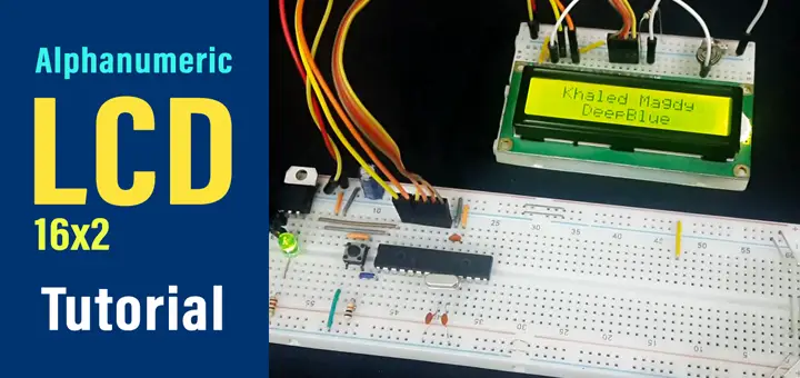
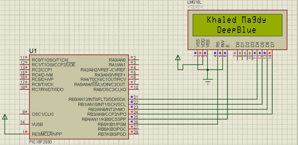
PIC16F LCD 16×2 Interfacing Example – LAB1
| Lab Name | Writing Text To LCD |
| Lab Number | 28 |
| Lab Level | Intermediate |
| Lab Objectives | Learn how to interface the LCD 16×2 module with a microcontroller and write text to it starting at a specific position. |
1. Coding
Open the MPLAB IDE and create a new project name it “LCD_16x2_LAB1”. If you have some issues doing so, you can always refer to the previous tutorial using the link below.

Set the configuration bits to match the generic setting which we’ve stated earlier. And if you also find troubles creating this file, you can always refer to the previous tutorial using the link below.

Now, open the main.c file and let’s start developing the firmware for our project.
Here is the Full Code Listing For This LAB
|
1 2 3 4 5 6 7 8 9 10 11 12 13 14 15 16 17 18 19 20 21 22 23 24 25 26 27 28 29 30 31 32 33 34 35 36 37 38 39 40 41 42 43 44 45 46 47 48 49 50 51 52 53 54 55 56 57 58 59 60 61 62 63 64 65 66 67 68 69 70 71 72 73 74 75 76 77 78 79 80 81 82 83 84 85 86 87 88 89 90 91 92 93 94 95 96 97 98 99 100 101 102 103 104 105 106 107 108 109 110 111 112 113 114 115 116 117 118 119 120 121 122 123 124 125 126 127 128 129 130 131 132 133 134 135 136 137 138 139 140 141 142 143 144 145 146 147 148 149 150 151 152 153 154 155 156 157 158 159 |
/* * File: main.c * Author: Khaled Magdy * LAB Number: 28 * LAB Name: Writing Text To LCD */ #include <xc.h> #include "config.h" #define _XTAL_FREQ 48000000 #define LCD_EN_Delay 500 #define LCD_DATA_PORT_D TRISB #define LCD_RS_D TRISB5 #define LCD_EN_D TRISB4 #define RS RB5 #define EN RB4 #define D4 RB0 #define D5 RB1 #define D6 RB2 #define D7 RB3 //========================================== //-----[ Prototypes For All Functions ]----- void LCD_Init(); void LCD_Clear(); void LCD_SL(); void LCD_SR(); void LCD_CMD(unsigned char); void LCD_DATA(unsigned char); void LCD_Set_Cursor(unsigned char, unsigned char); void LCD_Write_Char(char); void LCD_Write_String(char*); //------------------------------------------ void main(void) { LCD_Init(); LCD_Clear(); LCD_Set_Cursor(1,1); LCD_Write_String("Khaled Magdy\0"); LCD_Set_Cursor(2,1); LCD_Write_String(" DeepBlue\0"); while(1) { } return; } //============================================ //-----[ Alphanumeric LCD 16x2 Routines ]----- void LCD_DATA(unsigned char Data) { if(Data & 1) D4 = 1; else D4 = 0; if(Data & 2) D5 = 1; else D5 = 0; if(Data & 4) D6 = 1; else D6 = 0; if(Data & 8) D7 = 1; else D7 = 0; } void LCD_CMD(unsigned char CMD) { // Select Command Register RS = 0; // Move The Command Data To LCD LCD_DATA(CMD); // Send The EN Clock Signal EN = 1; __delay_us(LCD_EN_Delay); EN = 0; } void LCD_Clear() { LCD_CMD(0); LCD_CMD(1); } void LCD_Set_Cursor(unsigned char r, unsigned char c) { unsigned char Temp,Low4,High4; if(r == 1) { Temp = 0x80 + c - 1; //0x80 is used to move the cursor High4 = Temp >> 4; Low4 = Temp & 0x0F; LCD_CMD(High4); LCD_CMD(Low4); } if(r == 2) { Temp = 0xC0 + c - 1; High4 = Temp >> 4; Low4 = Temp & 0x0F; LCD_CMD(High4); LCD_CMD(Low4); } } void LCD_Init() { // IO Pin Configurations LCD_DATA_PORT_D = 0x00; LCD_RS_D = 0; LCD_EN_D = 0; // The Init. Procedure As Described In The Datasheet LCD_DATA(0x00); __delay_ms(30); __delay_us(LCD_EN_Delay); LCD_CMD(0x03); __delay_ms(5); LCD_CMD(0x03); __delay_us(150); LCD_CMD(0x03); LCD_CMD(0x02); LCD_CMD(0x02); LCD_CMD(0x08); LCD_CMD(0x00); LCD_CMD(0x0C); LCD_CMD(0x00); LCD_CMD(0x06); } void LCD_Write_Char(char Data) { char Low4,High4; Low4 = Data & 0x0F; High4 = Data & 0xF0; RS = 1; LCD_DATA(High4>>4); EN = 1; __delay_us(LCD_EN_Delay); EN = 0; __delay_us(LCD_EN_Delay); LCD_DATA(Low4); EN = 1; __delay_us(LCD_EN_Delay); EN = 0; __delay_us(LCD_EN_Delay); } void LCD_Write_String(char *str) { int i; for(i=0;str[i]!='\0';i++) LCD_Write_Char(str[i]); } void LCD_SL() { LCD_CMD(0x01); LCD_CMD(0x08); } void LCD_SR() { LCD_CMD(0x01); LCD_CMD(0x0C); } |
2. Simulation
Here is the simulation’s result.
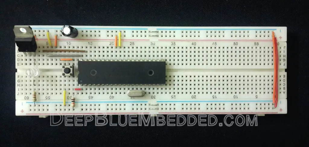
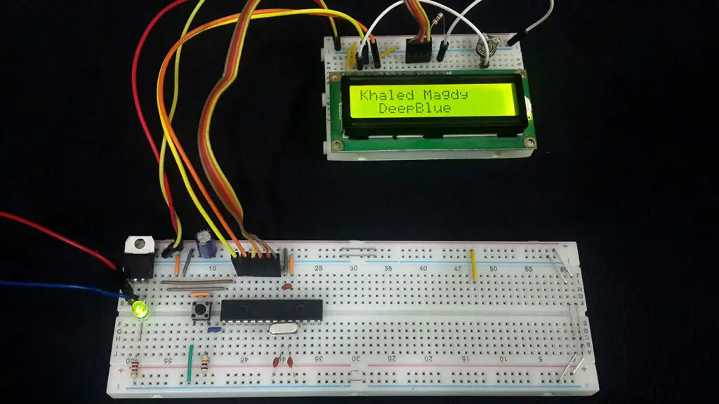
3. Prototyping
PIC Microcontroller LCD Moving Text – LAB2
| Lab Name | Writing A Moving Text On LCD |
| Lab Number | 29 |
| Lab Level | Intermediate |
| Lab Objectives | Learn how to interface the LCD 16×2 module with a microcontroller and write text to it starting at a specific position. |
1. Coding
Open the MPLAB IDE and create a new project name it “LCD_16x2_LAB2”. If you have some issues doing so, you can always refer to the previous tutorial using the link below.
Set the configuration bits to match the generic setting which we’ve stated earlier. And if you also find troubles creating this file, you can always refer to the previous tutorial using the link below.
Now, open the main.c file and let’s start developing the firmware for our project.
Here is the Full Code Listing For This LAB
|
1 2 3 4 5 6 7 8 9 10 11 12 13 14 15 16 17 18 19 20 21 22 23 24 25 26 27 28 29 30 31 32 33 34 35 36 37 38 39 40 41 42 43 44 45 46 47 48 49 50 51 52 53 54 55 56 57 58 59 60 61 62 63 64 65 66 67 68 69 70 71 72 73 74 75 76 77 78 79 80 81 82 83 84 85 86 87 88 89 90 91 92 93 94 95 96 97 98 99 100 101 102 103 104 105 106 107 108 109 110 111 112 113 114 115 116 117 118 119 120 121 122 123 124 125 126 127 128 129 130 131 132 133 134 135 136 137 138 139 140 141 142 143 144 145 146 147 148 149 150 151 152 153 154 155 156 157 158 159 160 161 162 163 164 165 166 167 168 |
/* * File: main.c * Author: Khaled Magdy * LAB Number: 28 * LAB Name: Writing Text To LCD */ #include <xc.h> #include "config.h" #define _XTAL_FREQ 48000000 #define LCD_EN_Delay 500 #define LCD_DATA_PORT_D TRISB #define LCD_RS_D TRISB5 #define LCD_EN_D TRISB4 #define RS RB5 #define EN RB4 #define D4 RB0 #define D5 RB1 #define D6 RB2 #define D7 RB3 //========================================== //-----[ Prototypes For All Functions ]----- void LCD_Init(); void LCD_Clear(); void LCD_SL(); void LCD_SR(); void LCD_CMD(unsigned char); void LCD_DATA(unsigned char); void LCD_Set_Cursor(unsigned char, unsigned char); void LCD_Write_Char(char); void LCD_Write_String(char*); //------------------------------------------ void main(void) { LCD_Init(); LCD_Clear(); LCD_Set_Cursor(1,1); LCD_Write_String("Khaled Magdy\0"); LCD_Set_Cursor(2,1); LCD_Write_String(" DeepBlue\0"); while(1) { for(int i=0; i<4; i++) { __delay_ms(300); LCD_SR(); } for(int i=0; i<4; i++) { __delay_ms(300); LCD_SL(); } } return; } //============================================ //-----[ Alphanumeric LCD 16x2 Routines ]----- void LCD_DATA(unsigned char Data) { if(Data & 1) D4 = 1; else D4 = 0; if(Data & 2) D5 = 1; else D5 = 0; if(Data & 4) D6 = 1; else D6 = 0; if(Data & 8) D7 = 1; else D7 = 0; } void LCD_CMD(unsigned char CMD) { // Select Command Register RS = 0; // Move The Command Data To LCD LCD_DATA(CMD); // Send The EN Clock Signal EN = 1; __delay_us(LCD_EN_Delay); EN = 0; } void LCD_Clear() { LCD_CMD(0); LCD_CMD(1); } void LCD_Set_Cursor(unsigned char r, unsigned char c) { unsigned char Temp,Low4,High4; if(r == 1) { Temp = 0x80 + c - 1; //0x80 is used to move the cursor High4 = Temp >> 4; Low4 = Temp & 0x0F; LCD_CMD(High4); LCD_CMD(Low4); } if(r == 2) { Temp = 0xC0 + c - 1; High4 = Temp >> 4; Low4 = Temp & 0x0F; LCD_CMD(High4); LCD_CMD(Low4); } } void LCD_Init() { // IO Pin Configurations LCD_DATA_PORT_D = 0x00; LCD_RS_D = 0; LCD_EN_D = 0; // The Init. Procedure As Described In The Datasheet LCD_DATA(0x00); __delay_ms(30); __delay_us(LCD_EN_Delay); LCD_CMD(0x03); __delay_ms(5); LCD_CMD(0x03); __delay_us(150); LCD_CMD(0x03); LCD_CMD(0x02); LCD_CMD(0x02); LCD_CMD(0x08); LCD_CMD(0x00); LCD_CMD(0x0C); LCD_CMD(0x00); LCD_CMD(0x06); } void LCD_Write_Char(char Data) { char Low4,High4; Low4 = Data & 0x0F; High4 = Data & 0xF0; RS = 1; LCD_DATA(High4>>4); EN = 1; __delay_us(LCD_EN_Delay); EN = 0; __delay_us(LCD_EN_Delay); LCD_DATA(Low4); EN = 1; __delay_us(LCD_EN_Delay); EN = 0; __delay_us(LCD_EN_Delay); } void LCD_Write_String(char *str) { int i; for(i=0;str[i]!='\0';i++) LCD_Write_Char(str[i]); } void LCD_SL() { LCD_CMD(0x01); LCD_CMD(0x08); } void LCD_SR() { LCD_CMD(0x01); LCD_CMD(0x0C); } |
2. Simulation
Here is the simulation’s result.
3. Prototyping
Concluding Remarks
1
In this tutorial, we’ve implemented some of the most common LCD commands that you are most likely to use in your various projects. However, there still are some other commands that you can implement and test on your own. Just get the datasheet and start tinkering around and if you feel stuck at any point, just drop me a comment and I’ll be here to help you.
2
As we’ve discussed in a previous section, it’s a recommended practice to separate your device drivers layer from the application layer as much as possible. It helps in terms of portability and enhances code re-usability. Each device driver should have a header file .h and a source file .c and you can #include this library in whichever project you want. Reducing the time to port your project to another platform (microcontroller).
3
You can use the sprintf function from the standard library by including stdio.h. Now you can combine numbers (int, float, etc) with text in a single array “string” that you can print out on your LCD. We’ve done this in a previous lab for the LM35 sensor.
4
LCD Custom Character Generator Tool
You can also use the free tool down below to generate your own custom characters and symbols for the LCD display. Things like speaker icon, battery level indicator, and so on.
Custom LCD Character Generator Online Tool
did you find this helpful? why not share it with your network or on reddit? maybe someone else find this helpful too! Good luck and have fun!
Regards,
| Previous Tutorial | Tutorial 25 | Next Tutorial | |||||
Hi Khaled, i love your tutorials!
But isn’t the EN delay of 500 us a bit long?
According to my LCD data sheet it should be 220 ns minimum. I’ve reduced the value to 1 us otherwise it doesn’t work on my end.
Greetings Marcel.
Thanks Khaled. The LCD tutorial is clear and well documented. I am using pic16f1619 microcontroller curiosity development board. Sadly I am unable to display characters. When I debug the program, everything works perfectly.
I had some problems getting this to work initially, until I realized that you did not have any delay after the function commands for things like clear screen and moving the cursor which take a lot of time.
Why the LCD_CMD function’s paramater is not separated into 2 nibbles, i dont understand 😦
Well, finally somebody that understands how dumb most of us are about new things. Thank you sir, your tutorial was most helpful.