| Previous Tutorial | Tutorial 17 | Next Tutorial | |||||
| EEPROMs (In Pic Microcontrollers) | |||||||
| Introductory Level ★☆☆☆☆ | |||||||
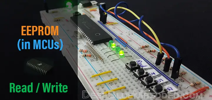
In this tutorial, you’ll learn what are EEPROM memories? How do they work? What are their applications? And how to interface the internal EEPROM memory within our PIC Microcontroller chip. We’ll also develop the required firmware drivers for EEPROM memory to perform Write/Read operations at any memory locations we want. This tutorial is somehow theoretical in nature but it’s fundamentally important and informative. So, let’s get started right now!
Required Components For This Tutorial
| Qty. | Component Name | Buy On Amazon.com |
| 1 | PIC16F877A | Add |
| 1 | BreadBoard | Add |
| 3 | LEDs | Add Add |
| 2 | Push Buttons | Add |
| 1 | Resistors Kit | Add Add |
| 1 | Capacitors Kit | Add Add |
| 1 | Jumper Wires Pack | Add Add |
| 1 | LM7805 Voltage Regulator (5v) | Add |
| 1 | Crystal Oscillator | Add |
| 1 | PICkit2 or 3 Programmer | Add |
| 1 | 9v Battery or DC Power Supply | Add Add Add |
[toc]
What is an EEPROM?
EEPROM, pronounced as Double-E-PROM, stands for Electrically Erasable Programmable Read-Only Memory. This kind of memory devices is re-programmable by the application of electrical voltage and can be addressed to write/read each specific memory location.
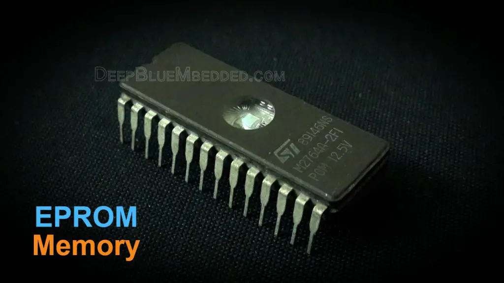
The EEPROM memory devices have evolved from the old EPROM memories. Which was the previous technology in this area. A typical EPROM has a window on the top side of the IC to allow the ultraviolet rays to reach the memory cells in order to erase the memory. The EPROMs had to be exposed to ultraviolet light for a convenient time period in order to get fully-erased.
You should also know that EEPROM memories are non-volatile. Which means it won’t lose the data contents when the power goes OFF. It can only be erased electrically whether it’s internal within a microcontroller (By Code) or external IC (By Electronic Device). On the contrary, the RAM memory is volatile. Which means it does lose all of its contents when the power goes OFF.
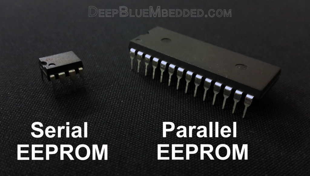
EEPROMs are fabricated and shipped as standalone IC chips and Microchip Technology has a significant share of this area in the market. External EEPROMs are manufactured to be interfaced in two different ways. There are parallel & serial address/data lines versions of EEPROMs.
However, we won’t be considering these devices in this tutorial. Instead, we’ll discuss the internal EEPROM memory integrated within the microcontrollers themselves.
The internal EEPROM memories (Built-in Within Microcontrollers) can be accessed for reading/writing operations by code. Writing a few lines of code will enable you of storing and/or retrieving data from the built-in EEPROM memory. And this is going to be our task in this tutorial. To develop the required firmware to drive this memory module.
Applications For EEPROMs
Let me give you a quick recap of the features of EEPROM memories before discussing their applications in real-life. A typical EEPROM device regardless of its type (internal/external) has the following features:
- Electrical erase-ability
- Electrical re-programmability
- Non-volatile memory locations
- Serial/Parallel interfaces for address/data lines (For External EEPROMs)
- Easy programmatically-controlled memory interface (For Internal EEPROMs)
With all of these features in mind. What applications do you think are a good fit for EEPROMs?
Well, there are many situations indeed. I’ll list down some of these and you can think of or search for any further applications. There is a ton of ways in which we can take advantage of the features provided by EEPROMs. And there are countless situations in which we use this kind of memory devices.
- If you’re building a computer system that needs to switch between programs (partially), you should have a memory to store these program instructions. Then you can easily load these instructions to your flash memory when you need to.
- Building an embedded system that needs to remember a user-given data even after a power-restart or a power-down condition. Such as a digital lock password-protected money locker. When the power goes OFF, the user’s password must be stored in a safe place.
- When you’re building a robot that’s doing a specific mission (scanning, searching, trolling around) where it’s collecting some sort of critical data. It’s a good idea to have a backup copy of this data on your local (internal) EEPROM. In an emergency, you can stream this data via a serial bus to your computer anytime you want.
- For a multi-computer system where there are many controllers working together in a robotic system or the like. If there is a sharable data, it’d be a good idea to store it on shared EEPROM via the serial bus (e.g. I2C). Any device can update/read this data without adding the overhead of sending/receiving data requests/updates between all the computers involved.
- And much more…
There are millions of EEPROM chips are being shipped every single year. These devices are actually embedded in almost all electronic devices you might ever know. If it’s not existent as a standalone IC chip, it should be integrated within the embedded computer (e.g. MCU) which controls your device behind the scenes.
Enough of theory! Let’s get some hands-on experience with a real EEPROM.
Internal EEPROM in PIC16F87XA
The PIC Microcontroller that we’ve chosen for these tutorials has the following EEPROM features:
- Up-to 256 x 8 Bytes of EEPROM Data Memory
- 1,000,000 Erase/Write Cycles EEPROM
- Low-Power, High-Speed EEPROM Memory
The (data EEPROM & Flash Program) Memory is readable and writable during normal operation (Over The Full VDD range). The EEPROM memory isn’t directly mapped in the register file space. Instead, it’s indirectly addressed through the special function registers (SFRs) dedicated to this job. There are exactly 6 SFRs used to Read/Write the EEPROM memory:
| EECON1 | EEDATA | EEADR |
| EECON2 | EEDATH | EEADRH |
| EECON1 | EECON1 is the control register for memory accesses. |
| EECON2 | EECON2 is not a physical register. Reading EECON2 will read all ‘0’s. The EECON2 register is used exclusively in the EEPROM 5-steps write sequence. |
| EEDATA | When interfacing to the data memory block, EEDATA holds the 8-bit data for read/write. |
| EEDATAH | When interfacing the program memory block, the EEDATA and EEDATH registers form a two-byte word that holds the 14-bit data for read/write. |
| EEADR | When interfacing to the data memory block, EEADR holds the address of the EEPROM location being accessed. |
| EEADRH | When interfacing the program memory block, the EEADR and EEADRH registers form a two-byte word that holds the 13-bit address of the program memory location being accessed. |
The EEPROM data memory allows single-byte read/write operations. The procedure for reading and writing the EEPROM memory locations is simplified by Microchip’s hardware designers. The typical step-by-step procedures for reading/writing is clearly given in the datasheet. And we’ll discuss them right now in the next section.
Writing / Reading Internal EEPROM
The exact steps for writing and reading EEPROM data memory locations are fully-listed in the microcontroller’s datasheet (page33). It’s going to be our own task to convert these step-by-step instructions to the c-code firmware. But, here I’ll list these steps as is
Steps For Writing To EEPROM
- If step 10 is not implemented, check the WR bit to see if a write is in progress.
- Write the address to EEADR. Make sure that the address is not larger than the memory size of the device.
- Write the 8-bit data value to be programmed in the EEDATA register.
- Clear the EEPGD bit to point to EEPROM data memory.
- Set the WREN bit to enable program operations.
- Disable interrupts (if enabled).
- Execute the special five instruction sequence:
• 1,2) Write 55h to EECON2 in two steps (first to W, then to EECON2)
• 3,4) Write AAh to EECON2 in two steps (first to W, then to EECON2)
• 5) Set the WR bit - Enable interrupts (if using interrupts).
- Clear the WREN bit to disable program operations.
- At the completion of the write cycle, the WR bit is cleared and the EEIF interrupt flag bit is set. (EEIF must be cleared by firmware.) If step 1 is not implemented, then firmware should check for EEIF to be set, or WR to clear, to indicate the end of the program cycle.
Steps For Reading From EEPROM
- Write the address to EEADR. Make sure that the address is not larger than the memory size of the device.
- Clear the EEPGD bit to point to EEPROM data memory.
- Set the RD bit to start the read operation.
- Read the data from the EEDATA register.
In the next section, we’ll write a c-code implementation for each of these procedures. We’ll be using these procedures in the practical LAB testing hereafter in this tutorial.
Implementing EEPROM W/R Firmware Driver
The best way to implement reading/writing procedures for EEPROM is to create a dedicated function for each process. The reading function takes an address value and returns the contents at this EEPROM memory location. Note that there are 256 EEPROM memory locations, hence we need only a Byte-Wide variable to address these locations. The writing function should be taking a Byte-Wide value to write and an address of a memory location to write at.
Writing To EEPROM
|
1 2 3 4 5 6 7 8 9 10 11 12 13 14 15 |
void EEPROM_Write(uint8_t Address, uint8_t Data) { while(EECON1bits.WR); // Waits Until Last Attempt To Write Is Finished EEADR = Address; // Writes The Addres To Which We'll Wite Our Data EEDATA = Data; // Write The Data To Be Saved EECON1bits.EEPGD = 0; // Cleared To Point To EEPROM Not The Program Memory EECON1bits.WREN = 1; // Enable The Operation ! INTCONbits.GIE = 0; // Disable All Interrupts Untill Writting Data Is Done EECON2 = 0x55; // Part Of Writing Mechanism.. EECON2 = 0xAA; // Part Of Writing Mechanism.. EECON1bits.WR = 1; // Part Of Writing Mechanism.. INTCONbits.GIE = 1; // Re-Enable Interrupts EECON1bits.WREN = 0; // Disable The Operation EECON1bits.WR = 0; // Ready For Next Writting Operation } |
Reading From EEPROM
|
1 2 3 4 5 6 7 8 9 |
uint8_t EEPROM_Read(uint8_t Address) { uint8_t Data; EEADR = Address; // Write The Address From Which We Wonna Get Data EECON1bits.EEPGD = 0; // Cleared To Point To EEPROM Not The Program Memory EECON1bits.RD = 1; // Start The Read Operation Data = EEDATA; // Read The Data return Data; } |
Internal EEPROM – LAB
| Lab Name | Internal EEPROM |
| Lab Number | 15 |
| Lab Level | Beginner |
| Lab Objectives | Learn how to use the internal EEPROM Memory to write/read data. Develop the necessary firmware in order to store some variables in the EEPROM memory. Then retrieve them back after a hardware restart for the microcontroller chip. Everything is done with some push buttons and LEDs. |
1. Coding
Open the MPLAB IDE and create a new project name it “Internal_EEPROM”. If you have some issues doing so, you can always refer to the previous tutorial using the link below.

Set the configuration bits to match the generic setting which we’ve stated earlier. And if you also find troubles creating this file, you can always refer to the previous tutorial using the link below.

Now, open the main.c file and let’s start developing the firmware for our project.
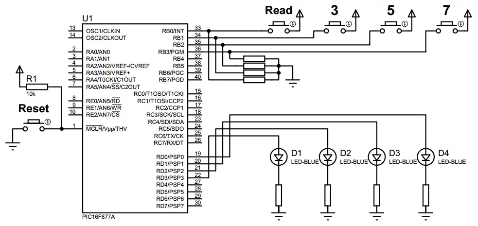
Our first task is to configure the io pins that we’ll be using for input (4-push buttons) and the output (4-LEDs). Which can be easily done by defining the following
|
1 2 3 4 5 6 7 8 9 10 |
//--[ Pin Definitions ]-- #define Read RB0 // Read EEPROM Memory Blocks #define W_3 RB1 // Write 0x03 #define W_5 RB2 // Write 0x05 #define W_7 RB3 // Write 0x07 //--[ IO Pins Configuration ]-- TRISB = 0x0F; // Push Buttons (Inputs) TRISD = 0x00; // Output LEDs PORTD = 0x00; // Initially OFF |
Then we head over to the main loop (routine). In which we should poll each of the input switches and perform the respective task when it’s pressed.
W_3 => should write 0x03 in the current EEPROM memory location, and increment the address pointer
W_5 => should write 0x05 in the current EEPROM memory location, and increment the address pointer
W_7 => should write 0x07 in the current EEPROM memory location, and increment the address pointer
Read => should read the first 3-bytes (memory locations) of the EEPROM and write them out to PORTD.
And of course, we have to add the definition of both functions EEPROM_Write() and EEPROM_Read()
And that’s all about the firmware for this lab.
The Full Code Listing
|
1 2 3 4 5 6 7 8 9 10 11 12 13 14 15 16 17 18 19 20 21 22 23 24 25 26 27 28 29 30 31 32 33 34 35 36 37 38 39 40 41 42 43 44 45 46 47 48 49 50 51 52 53 54 55 56 57 58 59 60 61 62 63 64 65 66 67 68 69 70 71 72 73 74 75 76 77 78 79 80 81 82 83 84 85 86 87 88 |
/* * LAB Number: 15 * LAB Name: Internal_EEPROM * Author: Khaled Magdy * For More Information Visit My Website @ DeepBlueMbedded.com * */ #include <xc.h> #include <stdint.h> #include "config.h" #define _XTAL_FREQ 4000000 //--[ Pin Definitions ]-- #define Read RB0 // Read EEPROM Memory Blocks #define W_3 RB1 // Write 0x03 #define W_5 RB2 // Write 0x05 #define W_7 RB3 // Write 0x07 //================================ //--[ Function Declarations ]-- void EEPROM_Write(uint8_t, uint8_t); uint8_t EEPROM_Read(uint8_t); //================================ void main(void) { //--[ IO Pins Configuration ]-- TRISB = 0x0F; // Push Buttons (Inputs) TRISD = 0x00; // Output LEDs PORTD = 0x00; // Initially OFF uint8_t Address=0; while(1) { if(W_3) // Write 0x03 { EEPROM_Write(Address++, 3); __delay_ms(500); } if(W_5) // Write 0x05 { EEPROM_Write(Address++, 5); __delay_ms(500); } if(W_7) // Write 0x07 { EEPROM_Write(Address++, 7); __delay_ms(500); } if(Address == 3) Address = 0; if(Read == 1) { // Read The EEPROM Data Out To PORTD LEDs for (uint8_t i=0; i<3; i++) { PORTD = EEPROM_Read(i); __delay_ms(1000); } } } return; } //======================================================= //--[ Functinos Definitions ]-- void EEPROM_Write(uint8_t Address, uint8_t Data) { while(EECON1bits.WR); // Waits Until Last Attempt To Write Is Finished EEADR = Address; // Writes The Addres To Which We'll Wite Our Data EEDATA = Data; // Write The Data To Be Saved EECON1bits.EEPGD = 0; // Cleared To Point To EEPROM Not The Program Memory EECON1bits.WREN = 1; // Enable The Operation ! INTCONbits.GIE = 0; // Disable All Interrupts Untill Writting Data Is Done EECON2 = 0x55; // Part Of Writing Mechanism.. EECON2 = 0xAA; // Part Of Writing Mechanism.. EECON1bits.WR = 1; // Part Of Writing Mechanism.. INTCONbits.GIE = 1; // Re-Enable Interrupts EECON1bits.WREN = 0; // Disable The Operation EECON1bits.WR = 0; // Ready For Next Writting Operation } uint8_t EEPROM_Read(uint8_t Address) { uint8_t Data; EEADR = Address; // Write The Address From Which We Wonna Get Data EECON1bits.EEPGD = 0; // Cleared To Point To EEPROM Not The Program Memory EECON1bits.RD = 1; // Start The Read Operation Data = EEDATA; // Read The Data return Data; } |
2. Simulation
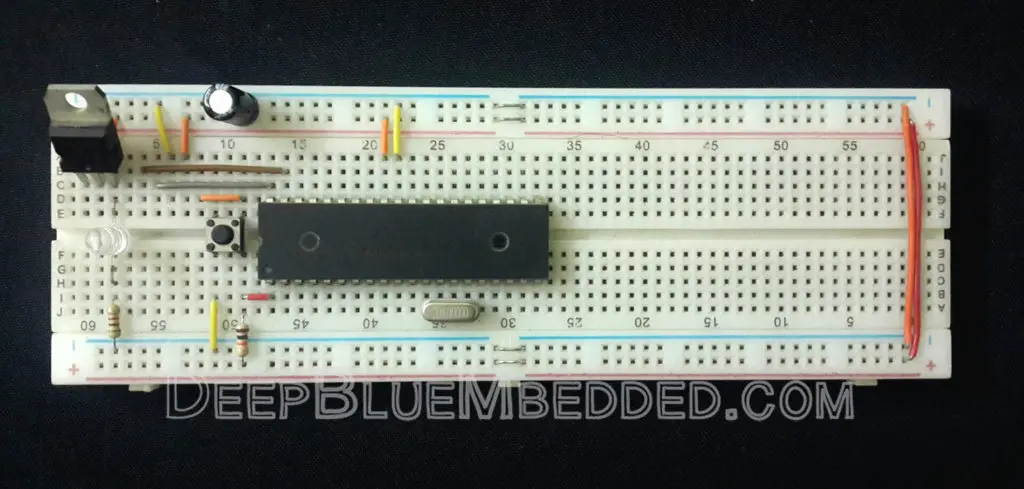
To simulate the project, just hook 4 LEDs to PORTD 4-LSBs pins. And 4 Pull-Down Push Buttons to PORTB 4-LSBs pins. Add the hex file and run the simulator. Here is the schematic for this lab
The running simulation test in case you’re curious
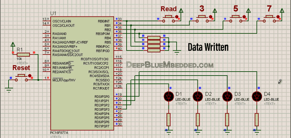
The same data is still resident in the same memory locations even after a hardware reset. Which is what we should expect from an EEPROM. So, it’s a success!
3. Prototyping
Prototyping this project should also be an easy task. The tough part has been already done before writing the code. And here is the output in case you’re curious.
 |
Tips + Concluding Remarks
1
During the EEPROM writing procedure, there was a critical 5-steps sequence of instruction that shouldn’t be interrupted anyway. That’s why we’ve disabled the global interrupt enable bit in the EEPROM_Write() function. And we’ve re-enabled interrupts immediately after executing the writing procedure. But, what if the interrupts were disabled for whatever reason?! then we just can’t simply re-enable interrupts after each EEPROM write operation.
However, the code shown above for this lab will work flawlessly for almost any small project. But in case you’re creating some sort of complex sophisticated systems. It’s going to be a better idea to use the code shown down below. In which I’m just saving the state of the GIE bit and restoring it back after each EEPROM write operation,
|
1 2 3 4 5 6 7 8 9 10 11 12 13 14 15 16 17 |
void EEPROM_Write(uint8_t Address, uint8_t Data) { uint8_t GIE_State; // Variable To Store The Last GIE State while(EECON1bits.WR); // Waits Until Last Attempt To Write Is Finished EEADR = Address; // Writes The Addres To Which We'll Wite Our Data EEDATA = Data; // Write The Data To Be Saved EECON1bits.EEPGD = 0; // Cleared To Point To EEPROM Not The Program Memory EECON1bits.WREN = 1; // Enable The Operation ! GIE_State = GIE; // Store The GIE State INTCONbits.GIE = 0; // Disable All Interrupts Untill Writting Data Is Done EECON2 = 0x55; // Part Of Writing Mechanism.. EECON2 = 0xAA; // Part Of Writing Mechanism.. EECON1bits.WR = 1; // Part Of Writing Mechanism.. GIE = GIE_State; // Restore The Interrupts Last State EECON1bits.WREN = 0; // Disable The Operation EECON1bits.WR = 0; // Ready For Next Writting Operation } |
2
Technically, you can think of the EEPROM as if it was a tiny Hard-Drive or an SD card. You can use it to store data (variables) that work as configurations for your system (e.g. passwords, bus address, MAC address, etc.). Which you want your system to keep remembering even after a hardware restart if the MCU has lost power for any reason at any time.
3
There is a maximum number of attempts to erase/re-write each of the EEPROM memory locations that is called (Endurance). It has been always a common thing to see EEPROMs with 10x times more endurance (erase/re-write cycles). Typically, 100k up-to 1kk cycles for EEPROMs, and 10k up-to 100k for Flash memories. On the other hand, EEPROMs shipped are always in the low-end sized memories. Compared to flash memory chips that have the majority of its shipments in the >4MB sized memories.
4
Unlike most other kinds of non-volatile memory, an EEPROM typically allows bytes to be read, erased, and re-written individually. Bulk (block) data transfer is also available for EEPROM as well as Flash memory type.
Nowadays EEPROM is emulated as a part of the flash. During the boot-up sequence, boot-loaders are written in such a way that they hold some signature on EEPROM (emulated) itself. Hence, we’re able to use some blocks of the flash as EEPROM memory. For further reading follow this thread.
| Previous Tutorial | Tutorial 17 | Next Tutorial | |||||
Excellent post. I definitely love this site.
Continue the good work!
I am confused about while(EECON1bits.WR) line of code.According to tutorial, it says when the writing process is completed, WR bit is cleared and EEIF bit is set.In this situtation, wouldn’t while(EECON1bits.WR) be always false?I mean if it is true then the writing process is still continuing, and if it is false the writing process cannot be done.
This line of code is just a precaution. It protects against going into the following state:
You initiate an EEPROM Write operation, while not using the interrupt signal which means EEIF bit is not checked, then for some reason, you call the function again to write another byte to EEPROM. Now it comes the role of this while(WR); delay. It prevents initiating another write operation while another one is in progress.
When the last write is done, the WR bit goes LOW. Which breaks the while(WR) loop, and our write function (routine) starts as expected.
Hope This Helps ^^
In the main() function for the read switch code I’m getting an error like… illegal conversation between types and non scalar types can’t be converted to other types.
PORTD=EEPROm_read(I);
I’m getting the above error for the above statement.Why is that so?