| Previous Tutorial | Tutorial 30 | Next Tutorial | |||||
| Servo Motor Control With PIC Microcontrollers | PWM | |||||||
| Intermediate Level ★★☆☆☆ | |||||||
Servo Motor Control Tutorial – PART1
In this Article / Tutorial, we’ll discuss how servo motor works. And how to control servo motor with pic microcontrollers. Why it’s difficult to generate 50Hz PWM with CCP in PIC Microcontrollers. And what are the different design solutions to control servo motors with microcontrollers? This article will address the CCP/PWM solution. Other methods for controlling servos will be introduced in future articles, such as: soft PWM, NCO, PCPWM, and much more!
Without further ado, let’s get started!
[toc]
Required Components For This Tutorial
| Qty. | Component Name | Buy On Amazon.com |
| 1 | PIC18F2550 | Add |
| 1 | BreadBoard | Add |
| 1 | Micro Servo Motor (Metal Gear) | Add |
| 1 | LED | Add Add |
| 1 | Resistors Kit | Add Add |
| 1 | Capacitors Kit | Add Add |
| 1 | Jumper Wires Pack | Add Add |
| 1 | LM7805 Voltage Regulator (5v) | Add |
| 1 | Crystal Oscillator | Add |
| 1 | PICkit2 or 3 Programmer | Add |
| 2 | 9v Battery or DC Power Supply | Add Add Add |
My DSO Siglent-SDS1104 (on Amazon.com)
My Function Generator Fy-6900 (on Amazon.com)
*Affiliate Links Disclosure: links will make me a small commission at no additional cost to you*
What Are Servo Motors?
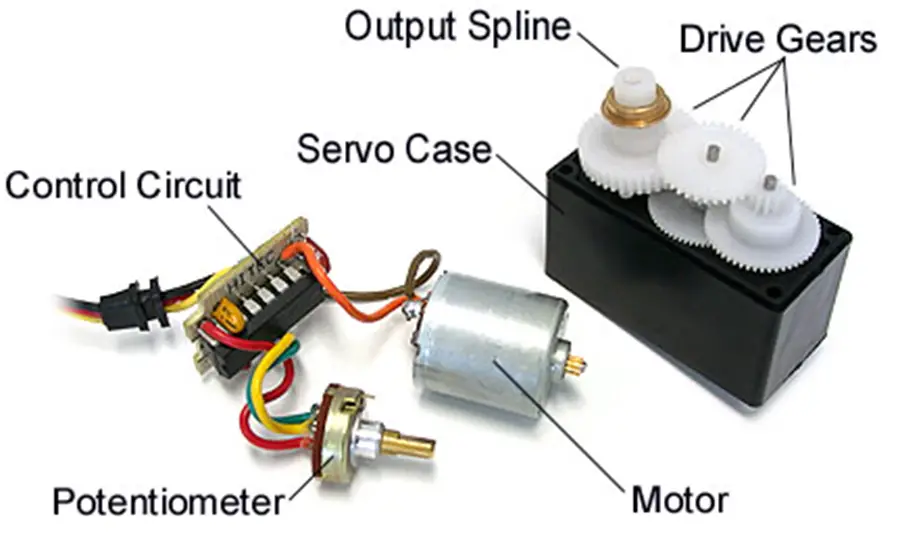
A servo motor is a closed-loop control system consisting of a DC motor, gearbox, and potentiometer to provide feedback information about the angular position of the motor to be controlled. Servo motors are typically used in applications where precise small angular motion is required.
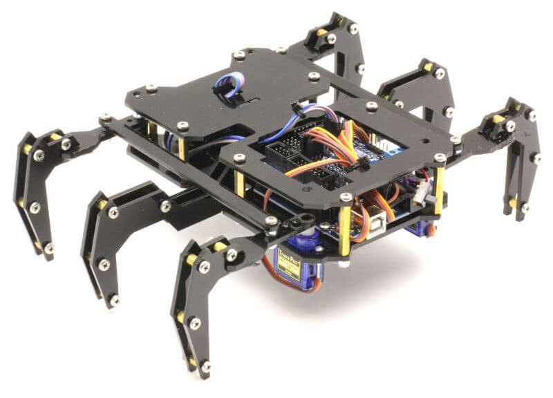
Servo motors are widely used in robotics, automation, and electromechanical systems in general. Which includes: robotic arms, small bots, hexapods, and bio-inspired robots, and much more…
Hereafter in this article, we’ll discuss how servo motors internally work and how to control servo motors with microcontrollers & even without using a microcontroller in order to test your servos on the bench for the purpose of verification. Sometimes you get defect parts and sometimes the timing diagrams given in datasheets are not the exact ones for a specific model of a servo motor.
How To Control Servo Motors?
The way servo motors are working is simply by comparing a reference voltage to the actual angular shaft position using a potentiometer attached to the gearbox. The reference voltage can be controlled by sending a 50Hz PWM (pulse-width-modulated) signal to the servo motor. Which in turn changes the reference voltage and the control circuitry steers the motor in the right direction until it reaches the exact required angle position and it keeps holding it while the PWM signal is not changing.
The diagram down below indicates the behavior of the servo motor’s shaft due to the change of the PWM pulse width. Typically the full sweep (0->180°) is achieved by sweeping the pulse width from (1ms to 2ms).
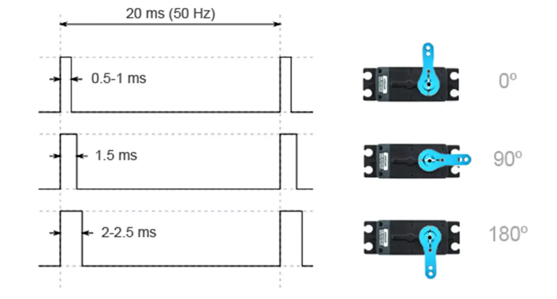
Different servo motors have different ranges for the pulse width of the 50Hz PWM signal which corresponds to the 0° position and 180° maximum angular position.
So, it’s important to double-check the datasheet for the specific servo motor you are using. However, it’s always best to take a test on the bench yourself because some servos come with a couple of Chinese papers that are poorly translated to English and may not be the exact documents for the attached servo motor at all!
And you’ll end up trying to figure out why your servo motor is not sweeping over the full scale using the values found in the “DATASHEET”.
Testing Servo Motor Without Microcontroller
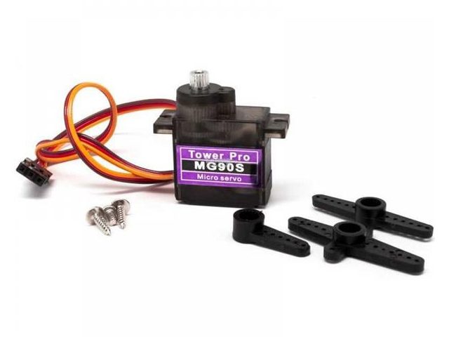
That’s the servo motor we’ll be using in this tutorial. The first search result that popped up in my face when i was googling for its datasheet was a document that turned out to be not so accurate in terms of the timing diagram for the PWM signal. Here is the diagram snippet from the datasheet.
And it turned out that the correct range for the PWM pulse width is 0.6ms to 2.4ms for angular motion from 0° to 180°. And that’s what we’ll be using for the test without and with a microcontroller.
Note That:
0.6ms of 20ms period is a 3% duty cycle (0° Position),
1.4ms of 20ms period is a 7% duty cycle (90° Position),
2.4ms of 20ms period is a 12% duty cycle (180 ° Position).
Speaking of the no-microcontroller test, you can use the bench signal generator to generate the required 50Hz PWM signal for the servo motor. And here are the functional settings I’ve programmed my DDS generator to perform.
- Square wave output signal 0-5v
- Fixed frequency 50Hz
- Sweep Function Activated for (Duty Cycle), Start value is 3%, End Value is 12%, Time period is 2 Seconds
The output signal from the DDS Function generator is connected to the servo motor signal pin. And here is the test demo video.
Servo Motor Control With PIC Microcontrollers
There are different ways to generate the 50Hz PWM signal required by the servo motor using a microcontroller. Speaking about PIC microcontroller, the first thing that should pop-up in your mind is the CCP PWM hardware module inside the microcontroller itself. But it turns out to be a little bit tricky business to get that right, here is why!
Why Is It Challenging To Use CCP PWM In PIC Microcontrollers To Control Servo Motors?
The problem stems from the fact that the timer2 period register used by the CCP PWM is an 8-Bit register and it can reach up to 255 at maximum. And here is the formula for the PWM frequency.
![]()
Let’s use the highest Prescaler possible (16) and the lowest Fosc you might have got (4MHz). The desired period is (1/50) to get 50Hz PWM Signal. Hence, the only unknown is the value to be written in PR2. By solving for PR2, it turns out to be 1249!! which is definitely way more than an 8-Bit (PR2) register can handle!
Even with a moderately low frequency (4MHz) oscillator, we still can’t generate a PWM signal that has a very low frequency near the 50Hz range. That’s the challenge!
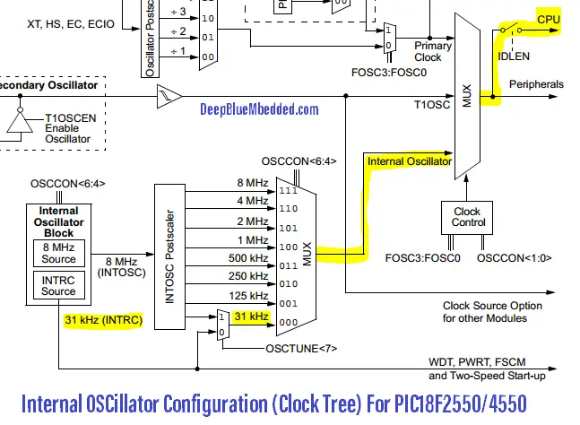
One simple solution (at least cheap in code) is to settle down for the internal low-frequency low-power RC oscillator (31250Hz) inside the microcontroller itself. By plugging this Fosc=31250 in the previous PWM period equation, the PR2 value will be 155! And that’s obviously in the 8-Bit range and achievable.
In the practical LABs hereafter, I’ll show you how to implement this solution and create a servo motor driver using the CCP PWM. However, down below are some other solutions that will be investigated in future articles (so stay tuned for that and please, keep sharing!).
What Are Some Other Design Techniques & Solutions To Control Servo Motors?
1 CCP PWM Hardware Module & Lowering Down Fosc using LP internal RC oscillator
(This solution is the one we’ll implement today).
2 Software PWM Generation Using Timer or Compare Match Interrupts
(Servo Motor Control Tutorial PART2 – With Soft PWM )
In a previous article, I’ve discussed the topic of software-generated PWM signals and how to precisely control the resolution, frequency, and duty cycle of it. You can refer to this article, or wait for the software PWM servo driving. But all in all, it’s a viable way to generate the 50Hz PWM signal and more importantly, it opens up the possibility to control any number of servo motors simultaneously (at least theoretically and @ high Fosc).
3 Using PCPWM module in Microchip PIC Microcontrollers
The Power Control PWM module from Microchip is available in a number of microcontrollers dedicated to motors and power control applications. Embedded systems designers for these sorts of applications are more familiar with this module and the dsPIC part with sophisticated PWM generation hardware.
The PCPWM hardware module is controlled by a total of 22 registers. And it has a larger time base registers and a very wide range of Prescaler values that makes your task much easier. The output channels may be up to 6 or 8.
4 Using NCO (Numerically Controlled Oscillator) Module
The NCO module from Microchip is available in too many microcontrollers especially the 8-Bit parts. This intelligent hardware module is capable of LINEARLY sweep over a wide range of frequencies and it can reach a resolution of 1/Fosc. I just can’t emphasize more how powerful and elegant this module is! It’s definitely a huge topic to be discussed in the future.
And it can potentially be the solution for a problem like a servo control. And let me show you how to do this but in another article!
Well, i think there still be other solutions like using external I2C servo driver and maybe combining CLC with timers. The list goes on, that’s enough for this section. Other solutions will be discussed and hopefully implemented in future articles. If you’re interested in that, please drop me a comment! i’d really like to know this!
Servo Motor Sweep – LAB1
| Lab Name | PWM – Servo Motor Sweep |
| Lab Number | 38 |
| Lab Level | Beginner |
| Lab Objectives | Learn how to use CCP modules to generate PWM signals @ 50Hz and control the position of a servo motor. |
In this LAB, we’ll replicate the Arduino servo example that sweeps over the angular position range from 0° up to 180° back and forth. The same as what you’ve seen in the previous test using my function generator.
Note: Refer to this tutorial, to learn all the calculations & setup steps for PWM
1. Coding
Open the MPLAB IDE and create a new project name it “Servo_Motor_PWM”. If you have some issues doing so, you can always refer to the previous tutorial using the link below.

Set the configuration bits to match the generic setting which we’ve stated earlier. And if you also find troubles creating this file, you can always refer to the previous tutorial using the link below.

Now, open the main.c file and let’s start developing the firmware for our project.
The full code listing for this lab is as follows
|
1 2 3 4 5 6 7 8 9 10 11 12 13 14 15 16 17 18 19 20 21 22 23 24 25 26 27 28 29 30 |
/* * File: main.c * Author: Khaled Magdy */ #include <xc.h> #include "config.h" #include "PWM.h" #define _XTAL_FREQ 31250 void main(void) { INTSRC = 1; // Fosc = 8MHz/256 = 31.25KHz OSCCON = 0x02; // Internal Oscillator Selection Setup_PWM1(); // DutyCycle Value (19 -> 75) = (3% -> 12%) unsigned int i=19; while(1) { PWM1_Set_DC(i++); __delay_ms(15); if(i>75) { __delay_ms(500); i=19; PWM1_Set_DC(i); __delay_ms(500); } } return; } |
2. Simulation
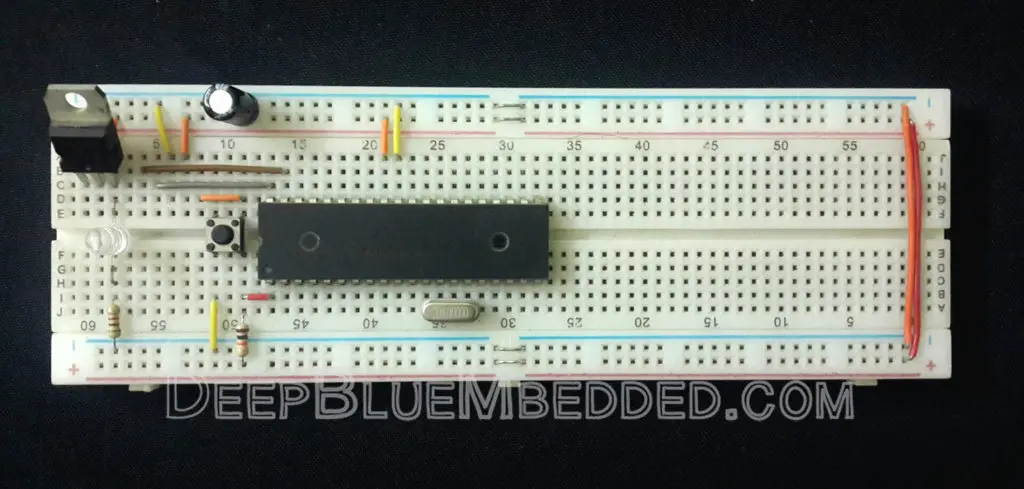
3. Prototyping
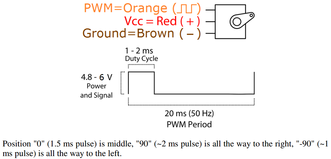
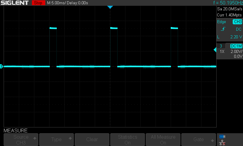
Connect the Brown wire to GND and the Red to Vdd and the Orange to RC2 (CCP1 PWM Pin). And turn on the power supply. The 50Hz PWM signal is captured by my DSO (digital storage oscilloscope).
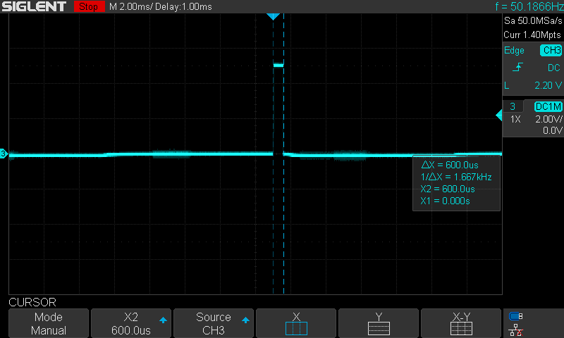
At position 0° the Duty Cycle is 3% And by measuring the pulse width it turns out to be exactly what we’ve designed for (0.6ms)!
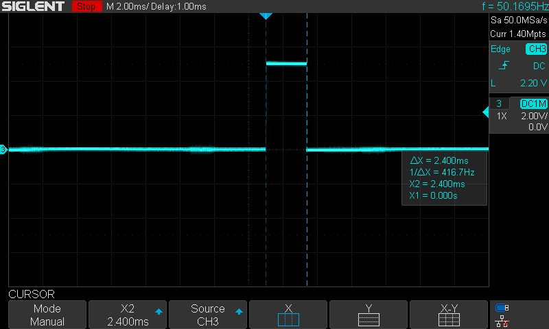
At position 180° the Duty Cycle is 12% And by measuring the pulse width it turns out to be exactly what we’ve designed for (2.4ms)!
Here is a short demo video for the running test for this LAB
 |
Servo Motor Manual Knob – LAB2
| Lab Name | PWM – Servo Motor Knob |
| Lab Number | 39 |
| Lab Level | Beginner |
| Lab Objectives | Learn how to use CCP modules to generate PWM signals @ 50Hz and control the position of a servo motor. |
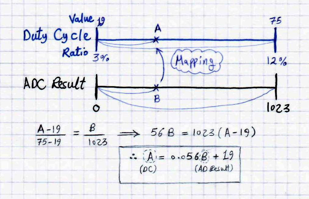
In this LAB, we’ll replicate the Arduino servo example that uses the ADC and potentiometer to manually control the position of the servo motor using the analog input. We’ll read the AN1 channel, then the AD_RES result will get mapped to fit in the range of the servo PWM duty cycle 3% to 12% or 19 to 75.
Note: Refer to this tutorial, to learn all the calculations & setup steps for PWM
1. Coding
Open the MPLAB IDE and create a new project name it “Servo_Motor_Knob”. If you have some issues doing so, you can always refer to the previous tutorial using the link below.
Set the configuration bits to match the generic setting which we’ve stated earlier. And if you also find troubles creating this file, you can always refer to the previous tutorial using the link below.
Now, open the main.c file and let’s start developing the firmware for our project.
The full code listing for this LAB is as follows
|
1 2 3 4 5 6 7 8 9 10 11 12 13 14 15 16 17 18 19 20 21 22 23 24 25 26 27 28 29 30 |
/* * File: main.c * Author: Khaled Magdy */ #include <xc.h> #include "ADC.h" #include "PWM.h" #include "config.h" #define _XTAL_FREQ 31250 void main(void) { INTSRC = 0; // Fosc = 8MHz/256 = 31.25KHz OSCCON = 0x02; // Internal Oscillator Selection unsigned int AD_RES, DC = 19; Setup_PWM1(); ADC_Init(); while(1) { // Read The ADC Channel GO_nDONE = 1; while(GO_nDONE); AD_RES = (ADRESH<<2)+(ADRESL>>6); // Mapping From ADC_RES To DutyCycle DC = 0.056*AD_RES+19.0; // Set The DC To Change The Servo Motor Angluar Position PWM1_Set_DC(DC); } return; } |
2. Simulation
3. Prototyping
Despite the fact that the simulation test did run smoothly but the poor PWM resolution due to the very low-frequency makes the servo inconsistent in movement. Moreover, the low RC oscillator for the Fosc did make the whole system a lot slower so it takes time to convert the A/D channel then change the PWM pulse width.
All in all, it did prove that the CCP PWM could be used but don’t expect it to be so great. Other solutions are coming in the next tutorials. Here is the demo video for this awful test!
|
Concluding Remarks
1
Yea, CCP PWM Can Be Used To Control Servo Motors. But…
But it has very limited (poor) resolution @ the operating frequency of 50Hz. And also it has pushed us to settle down for a very low running CPU frequency of 31250Hz or so. That’s not sufficient if your microcontroller has to perform any sort of processing!
Obviously using the CCP PWM was a not-so-good solution. But it was worth the try in order to get some results that are comparable to other design solutions and techniques which we’ll be discussing in the next tutorials. Let’s see if we can get much better results. Stay tuned for that!
2
Servo Motor Set Angle
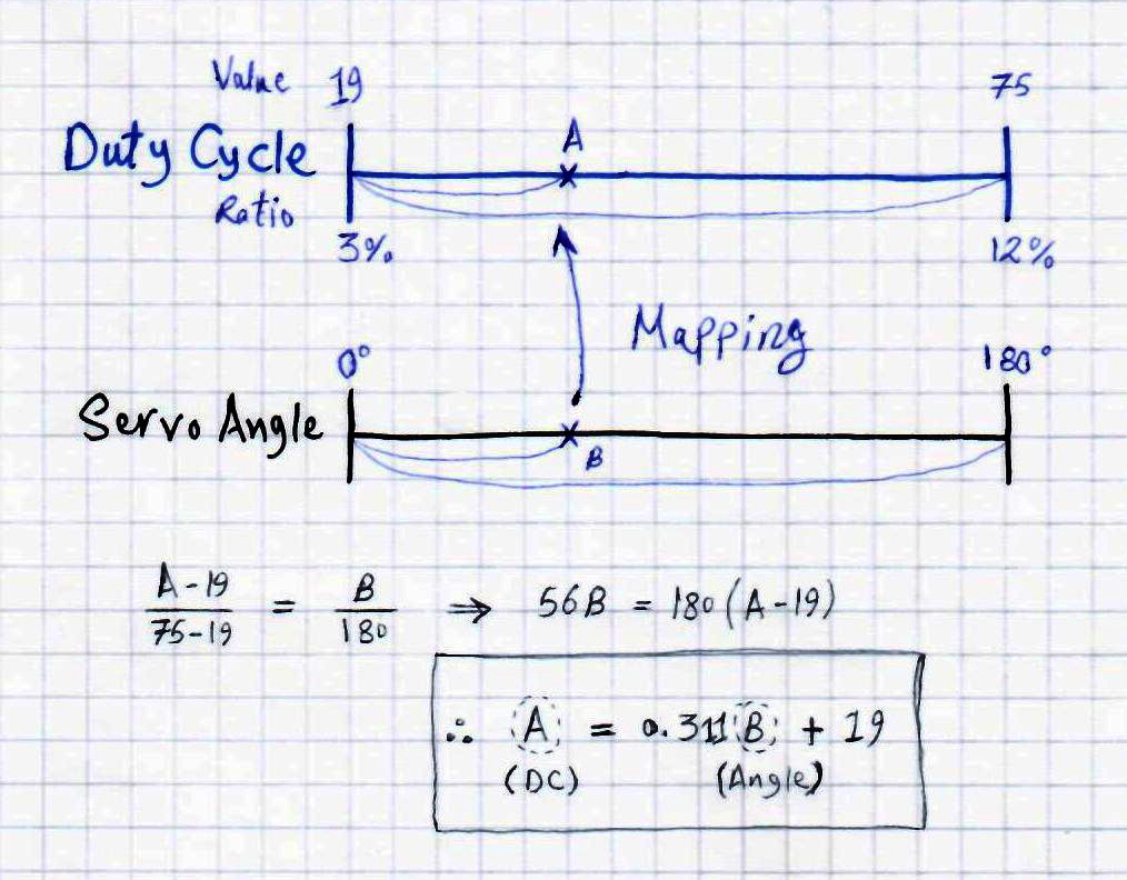
You can also easily create a mapping function to map the servo motor angle (angular position) to the PWM duty cycle. Over the full range using the formula derivation below. The same way as we’ve done in the knob control LAB previously.
The C-Code for the function implementation maybe something like this below.
|
1 2 3 4 5 6 |
void Servo_MoveTo(unsigned char Angle) { // Angle is ranging from 0 upto 180 int DC = 0.3111*Angle + 19; PWM1_Set_DC(DC); } |
3
Power Supply Precautions
Please, pay attention to power supply issues that arise when dealing with any kind of loads such as motors or so. Make sure to connect convenient decoupling capacitors on your microcontroller’s board. And to separate the power supply source if you’re going to use multiple servo motors.
Motor motion causes fluctuation in current being drawn by your circuit which causes voltage fluctuation in case of using not-so-good power supply circuitry. This can cause your microcontroller to restart very frequently, so please pay attention to this.
4
Don’t forget to SHARE these articles/tutorials. And let me know in the comments what do you think? Do you have any other ideas? maybe questions or problems?
I’ll be always here for help!
Regards ^^
Khaled M.
| Previous Tutorial | Tutorial 30 | Next Tutorial | |||||
Hi Khaled,
Thanks a lot for your blog, I followed the advice for the sensor and got it working with PIC32MX320F128H.
That’s amazing! Thanks for your feedback though ^^
Part3 of this tutorial is coming up very soon and I’m pretty sure it’s gonna appeal to you as well!
Hi, Khaled. Great Tutorial.
I have a small problem that im unable to understand. When mapping angular position to DC from 3% to 12% or 19 to 75, can you explain how 3% -> 19 and how 12% -> 75 ?
Greetings Qasim,
Thanks for the feedback and that nice question. The limits for that mapping operation stem from the following equation (in the datasheet).
Let’s put the values we’re using and get the digital value that we’ve to write in order to get a 100% duty cycle. OK?
The 100% DutyCycle is when The Duty = The Period of the signal. The period T = 1/F = 1/50 = 20mSec = 0.020 sec
PWM_Duty_Cycle = DC_Registers * Tosc * T2_Prescaler
0.020 = DC_Registers * 1/31.25KHz * 1
Solving for DC_Registers, it turns out to be 625
Well, In order to get 100% DC you’ve got to write 625 in the (CCPR1L:CCP1CON<5:4>) register pair.
100% -> 625
3% -> x
12% -> y
x = 3 * 625 / 100 = 19
y = 12 * 625 / 100 = 75
I hope you got it now! And I’ll be always here for any question. Good luck with your projects ^^
Regards,
Thanks For the great Tutorial!
I am doing the same with PIC16F1517.
Really helpful!
Can i use the pic16f877a for this tutorial?
Yeah, sure