| Previous Tutorial | Tutorial 12 | Next Tutorial | |||||
| Ultrasonic Sensor HC-SR04 With PIC Microcontrollers | |||||||
| Introductory Level ★☆☆☆☆ | |||||||
in this tutorial, you’ll learn how HC-SR04 ultrasonic sensors work and how to interface them with pic microcontrollers in MPLAB IDE XC8 compiler. we’ll also discuss what are their applications and how to use this sort of sensor with microchip pic microcontrollers. We’ll be developing the necessary firmware to interface the ultrasonic sensor and display the readings on a breadboard. It’s going to be an interesting tutorial, so let’s get started!
[toc]
Components Needed For This Tutorial
| Quantity | Component Name |
| 1 | PIC16F877A |
| 2 | Breadboard |
| 1 | Jumper Wires Pack |
| 1 | HC-SR04 Ultrasonic Sensor |
| 4 | LEDs |
| 4 | 330Ω Resistors |
| 1 | 4MHz Crystal OSCillator |
| 1 | LM7805 Voltage Regulator |
| 1 | 9v Battery or any Power Supply Source |
| 1 | PICkit3 (PIC Programmer) |
What Is An Ultrasonic Sensor?
An ultrasonic sensor is an electronic device that is typically used for distance measurement and/or object detection. This sort of sensors is very common in the makers’ community as well as industrial applications. Ultrasonic sensors are usually used for embedded systems projects/applications. That’s why we’ll learn how to interface this sensor in our series of tutorials. They are pretty cheap and easy to get sensors and could be interfaced with minimal electronic circuitry setup & as little of coding as operating a timer module.
Features of The HC-SR04 Sensor
| Operating Voltage | +5v DC |
| Operating Current | 15mA |
| Operating Sound Frequency | 40kHz |
| Measuring Angle Range (Sight Of Vision) | < 15° |
| Effective Measuring Field (Angle) | 30° |
| Measurement Resolution (Accuracy) | Up To 3mm |
| Measurements Range (Theoretically) | 2cm To 400cm |
| Measurements Range (Practically) | 2cm To 120cm |
| Trigger Input Pulse-Width | 10µs |
| Dimensions Of The Module | 45mm x 20mm x 15mm |
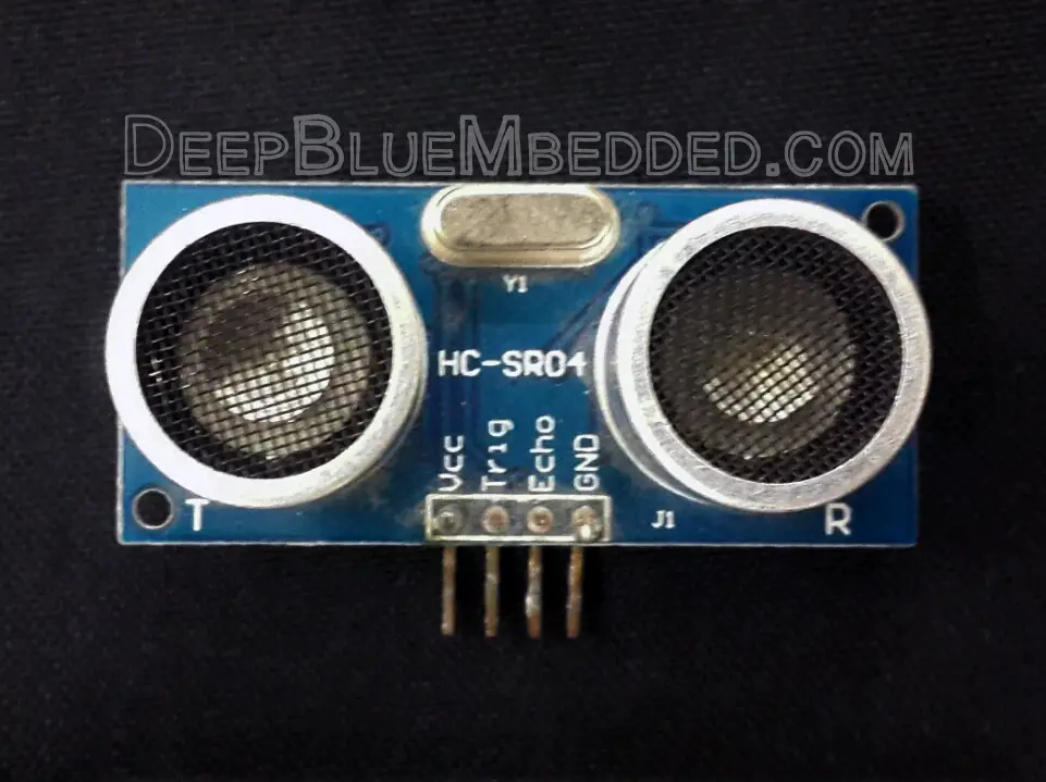
Ultrasonic Sensor HC-SR04 Pinout
| Pin | Pin Name | Functionality |
| 1 | Vcc | +5v DC Power Supply Input Pin |
| 2 | Trigger | Input Trigger Pulse That Starts The Sensor’s Operation |
| 3 | Echo | Output Pin which is connected to an input pin on the MCU to read the sensor’s measurements output. |
| 4 | Ground | 0v (Ground) Power Supply Input Pin |
The module board of the sensor itself has some sort of digital control circuitry that’s why there are 2 power pins (Vcc & Vss) in order to power it up. There are also a couple of pins (Trigger & Echo) which are used for operating the sensor.
Knowing how this sensor actually works not only will help you use it for the right applications. It’ll also help you to identify when it fails or when it’s a better idea to search for another sensor that would be a better fit for the target application. So let’s see how it works?
How Does An Ultrasonic Sensor Work?
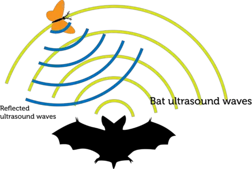
As the name suggests, the ultrasonic sensor’s operation is mainly dependent on ultra-sound waves. This is typically the way that Bats are using for vision and navigating around. They send some sound waves in the air, which will reflect back to them to tell how close an object is to the source of the sound wave. You should also know that the ultrasound waves are not detected by the human ears which hear low-frequency tones up to 20kHz.
Our sensor works in a similar fashion. It sends out ultrasonic sound waves then receives it back, then calculates the time it took the sound to travel from the source to the target. Which will obviously tell how far the target is from the sensor. That’s easily calculated due to the fact that sound travels in air at a constant speed.
Let’s formulate the whole process more technically!
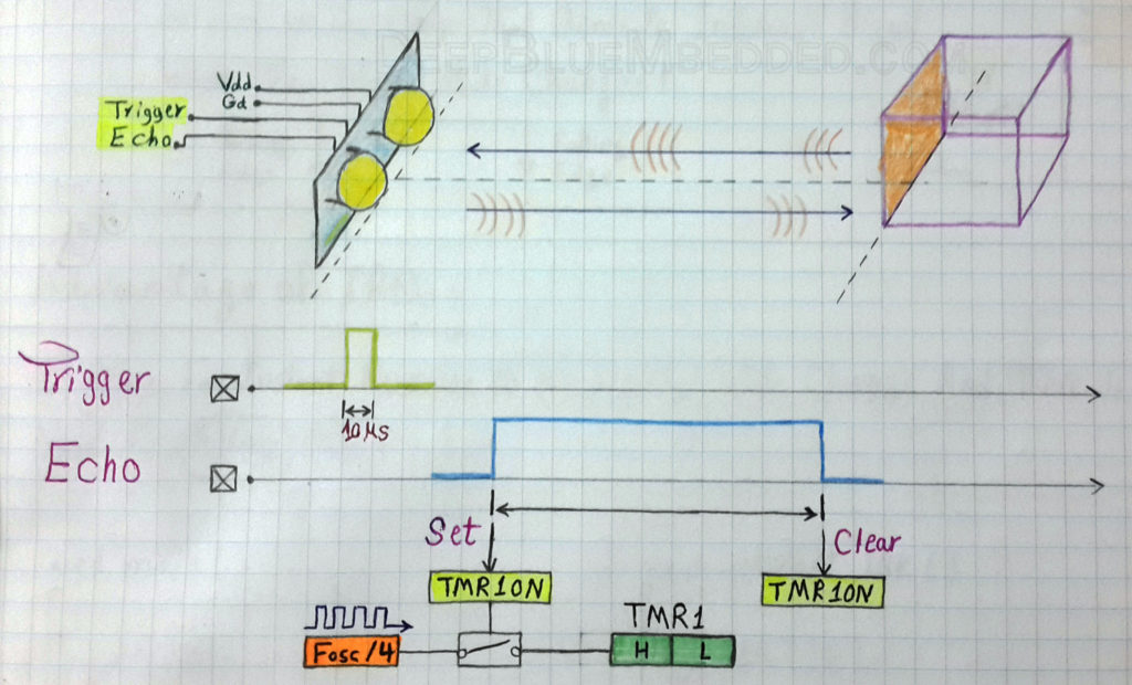
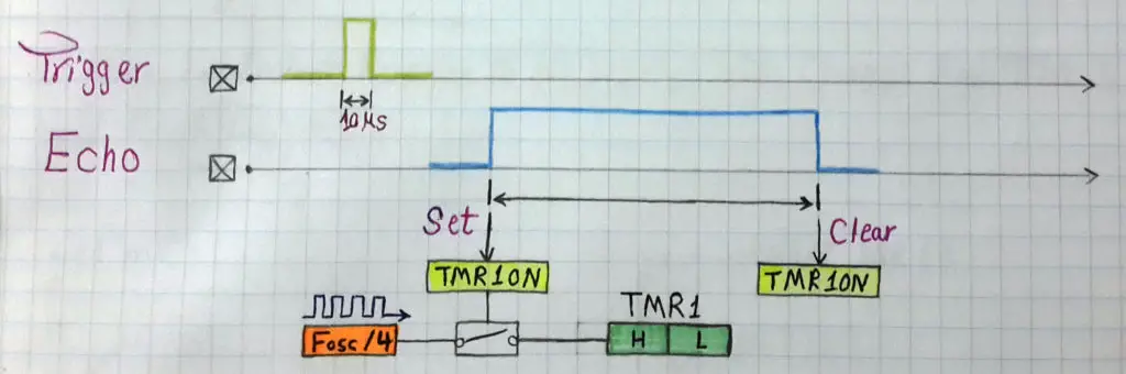
First, we activate the trigger pin of the ultrasonic sensor by giving it a short pulse (10µS). Consequently, the sensor will send out an ultra-sound wave that will travel along in the air until it hits something. If the sound wave has hit something it’ll reflect back to the sensor. Which will identify how long it took the sound wave to travel back and forth. Actually, this is the information that we’re willing to read from the sensor! We need to know how long it took the sound wave to go back and forth (between the sensor & the target).
The sensor sends out a pulse on the echo pin. In fact, this pulse captures the information that we’re looking for. As the width of the echo pulse is identical to the time of sound trip!
Yes, as you might be thinking. The ultrasonic sensor sends an ultrasound wave and calculates how long it takes that wave to hit a target and get back to the source. Then the sensor will output an echo pules that has a similar time duration for us to read. After calculating this pulse’s width, we can easily find out what is the distance between the sensor and the target using the following formula.

Note that, the EchoTime is the time it took the sound wave to travel back and forth between the sensor and the object that’s why we’re dividing it by 2 to get only the straightforward trip time. Sound waves travel in the air at a constant speed of 340m/s, so it’s an easy process to find out the distance measurement.
How To Interface An Ultrasonic Sensor With A µC?
Technically speaking, all we need is a couple of IO pins and a hardware Timer module
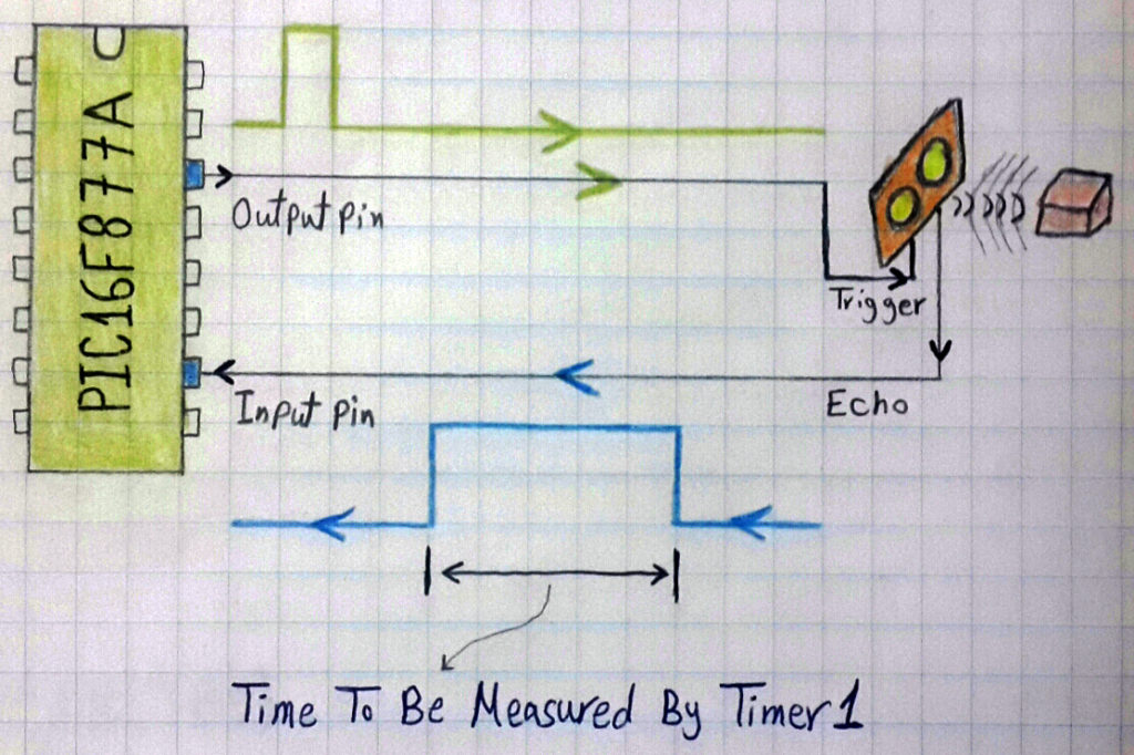
The first io pin should be configured as an output pin which will hook to the trigger pin of the ultrasonic sensor. A typical trigger signal is achieved by driving the trigger pin to high for a period of 2µS, Then drive it back to low.
The second io pin should be configured as an input pin which will be hooked to the echo output pin of the ultrasonic sensor. Now, it’s the time to measure the width of the echo pules coming from the sensor. We’ll wait for the echo pin until it’s driven high by the sensor, then we’ll start the Timer module (e.g. Timer1) by setting the TMR1ON bit. Then, we’ll wait until the echo pin is driven back to low. When it returns to the low state, this indicates the termination of the pulse. And we should stop the timer module by clearing the TMR1ON bit.
Now, the time period which we’re interested in is simply existing in the TMR1 register. The value stored in the 16-Bit TMR1 register can now tell us exactly how long did it take the sound wave to travel back and forth between the sensor and the target object. You can find out the Time (T) using the equation (T = number_of_ticks x time of each tick), formulated as shown below
 You should have noticed that we’re not interested in the full-time period of the sound trip back and forth. We’re actually interested in only half of it in order to find the distance between the sensor and the target. That’s why we should divide T by 2 afterward.
Now, we’ve got the time of the sound trip (more accurately, the forward half-time) & the speed of sound propagation in the air which is a constant of (340m/s). So it’s very easy to find out the distance using the following formula

After simple manipulations, conversion, and by relating the timer output T to the time in the last formula. We can finally get an equation that maps TMR1 value to distance (in cm). It’ll turn out to be as follows
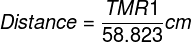
And that is the equation we’ll be using in writing the firmware code for the ultrasonic sensor. You can also double check and verify this equation on your own to make sure everything is OK.
Implementing An Ultrasonic Driver Procedure
Here we’ll start implementing the firmware drive (C-Code) for the ultrasonic sensor step-by-step. So let’s get started!
Step1 – Configure The IO Pins
As we’ve stated earlier in the previous section, we should configure a couple of io pins for both triggering the sensor (output pin) and reading the output pulse (input pin). let’s use RC2 and RC3 pins.
|
1 2 |
#define trigger RC2 #define echo RC3 |
And in the main function, we’ll set them to be output and input respectively
|
1 2 3 4 5 6 7 8 9 10 11 |
void main() { // Configure The IO Pins TRISB1 = 0; TRISB2 = 1; ... while(1) { ... } } |
Step2 – Configure The Timer Module
The Next step is obviously to configure the Timer1 module in order to operate in timer mode. We’ve done this many times in the previous tutorials, so let’s copy&paste that code snippet as is.
|
1 2 3 4 5 6 7 8 9 |
// -- [[ Configure Timer1 To Operate In Timer Mode ]] -- // Clear The Timer1 Register. To start counting from 0 TMR1 = 0; // Choose the local clock source (timer mode) TMR1CS = 0; // Choose the desired prescaler ratio (1:1) T1CKPS0 = 0; T1CKPS1 = 0; |
Note that we shouldn’t start the timer module operation right now, so it should be OFF.
Step3 – Write the Distance Calculation Procedure
The best way to go about implementing the distance calculation procedure is to create a dedicated function that handles everything and returns back the measured distance value! The declaration for this function should precede the main function. It’ll be something like this
|
1 |
int calc_distance(void); |
A function called calc_distance that takes no inputs but it handles the ultrasonic sensor interfacing procedure and returns back an integer value which represents the measured distance. You should notice that the distance value will always have a fraction part. But for sake of simplicity, we’ll discard that part of the output value by writing it to an integer.
The definition for this function could be placed either before or after the main function. From my experience, it’s a better practice to keep drivers in a completely separate header. But for this tutorial, we’ll place it right after the main function. The definition for this procedure should be as follows
|
1 2 3 4 5 6 7 8 9 10 11 12 13 14 15 16 17 18 19 20 21 |
// Definition Of The calc_dist() Function int calc_dist(void) { int distance=0; TMR1=0; // Send Trigger Pulse To The Sensor trigger=1; __delay_us(10); trigger=0; // Wait For The Echo Pulse From The Sensor while(!echo); // Turn ON Timer Module TMR1ON=1; // Wait Until The Pulse Ends while(echo); // Turn OFF The Timer TMR1ON=0; // Calculate The Distance Using The Equation distance=TMR1/58.82; return distance; } |
Summary For Interfacing The HC-SR04 Sensor
As you might have noticed, the procedure is typically some consecutive easy steps as listed down below
- Send a trigger signal
- Wait for the echo to come from the sensor
- When the echo signal arrives, start the timer module
- When the echo signal is driven back to low, then stop the timer
- Convert the time reading to real-time period then to a distance in cm
- Check the validity of the calculated distance and return it back to the caller
And that’s all about it!
Ultrasonic Sensor HC-SR04 Interfacing – LAB
| Lab Name | Ultrasonic Sensor HC-SR04 Interfacing |
| Lab Number | 9 |
| Lab Level | Beginner |
| Lab Objectives | Learn how to use ultrasonic sensors with microcontrollers. How to read distance measurements with an ultrasonic HC-SR04 sensor module. |
Disclaimer
In this LAB we’ll be using the same procedure which we’ve discussed earlier. Meaning that we’ll be discarding fraction parts. We’ll be getting discrete distance measurements (e.g. 5cm, 6cm, 7cm, and so on). The reason behind this is that we haven’t yet discussed serial communication protocols. So we can’t send floating-points values (e.g 5.32, 6.76 or 9.54 cm) to a computer to display on the screen. On the other hand, we haven’t yet developed LCD screen drivers. The display method we’ll be using in this LAB is just an LED bar! That’s why fractions can and will be neglected. An updated version of the firmware will be provided after some serial communication tutorials, So stay tuned!
1. Coding
Open the MPLAB IDE and create a new project name it “Ultrasonic Sensor”. If you have some issues doing so, you can always refer to the previous tutorial using the link below.

Set the configuration bits to match the generic setting which we’ve stated earlier. And if you also find troubles creating this file, you can always refer to the previous tutorial using the link below.
Now, open the main.c file and let’s start developing the firmware for our project.
Our first task is to configure the IO pins for echo & trigger functions. Then, we’ll define the _XTAL_FREQ identifier as we’ll be using the __delay_ms macro in our project. And also we should declare the calc_distance function which we’ve discussed earlier.
|
1 2 3 4 |
#define _XTAL_FREQ 4000000 #define trigger RC2 #define echo RC3 int calc_distance(void); // Function Declaration |
In the main routine, we’ll configure the IO output pins and the Timer1 module to be ready for use when we call the calc_distance function. And we’ll also create a variable dist in which we’ll be storing the sensor’s readings.
|
1 2 3 4 5 6 7 8 9 10 11 12 13 14 15 16 17 18 19 20 21 22 23 24 25 26 27 28 29 30 31 32 33 34 35 36 37 38 39 40 |
void main(void) { // Create Distance Variable int dist=0; //--[ Configure The IO Pins ]-- // Set PORTB To Be Output Port (All The 8 Pins) TRISB = 0x00; // Set PORTB To Be LOW For initial State PORTB = 0x00; // Set RC2 To Be Output Pin ( Trigger ) TRISC2 = 0; RC2 = 0; // Set RC3 To Be Input Pin ( Echo ) TRISC3 = 1; //--[ Configure Timer Module To Operate in Timer Mode ]-- // Clear The Pre-Scaler Select Bits T1CKPS0=0; T1CKPS1=0; // Choose The Local Clock As Clock Source TMR1CS=0; // Write The System's Main Routine ! while(1) { dist = calc_dist()/5; if(dist==1) {PORTB = 0x01; __delay_ms(50);} if(dist==2) {PORTB = 0x03; __delay_ms(50);} if(dist==3) {PORTB = 0x07; __delay_ms(50);} if(dist==4) {PORTB = 0x0F; __delay_ms(50);} else {PORTB = 0x00; __delay_ms(50);} } return; } |
The idea here is to turn ON an LED if the distance is larger than 5cm, and turn ON 2 LEDs if the distance exceeds 10cm and so on. Meaning that we’re turning ON an LED for each 5cm and turning them OFF one-by-one while the distance is dropping down by 5cm. That’s easily implemented by a switch or if-statements as shown in the code above.
The full code listing is provided in the attachments section at the end of this tutorial. Get everything done! Cross your fingers! Hit the compile button and we’re done!
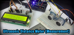
2. Prototyping
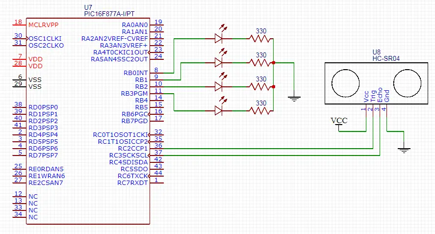
Make sure to connect everything as supposed to and you can follow the schematic diagram for this LAB. And don’t forget to flash the code to your microcontroller chip.
Here is a video for the running project output in case you’re curious
 |
Pro Tips + Concluding Remarks
From my experience, the ultrasonic sensor is one of the most popular sensors in the market. Almost everyone in our industry had some sort of hands-on experience with these electronic devices. However, all the problems we face in many situations are not shared on the web or more specifically in the same place we learn about this stuff!
I’ve designed my website so as not to be (do that and that and copy&paste that code) kind of tutorials. That’s why I’ll now give you some tips and tricks about the ultrasonic sensor to make sure your knowledge base is actually ready for some real testing.
1
Blind Zone
A remarkable notice about the fundamental limitations of an ultrasonic sensor is the range of operation. Which is typically (2 up to 400) cm. Well, there are many reasons to accept the upper limit of the sensor’s range. But why it can’t measure distances that are about 2cm or less?
The short answer = That’s because of the Blind Zone effect!
Let’s investigate a little bit more into this. The transceivers on the ultrasonic sensor’s board are cooperatively operating to send and detect ultrasound waves. Each of them is either transmitting or receiving sound waves.
When the sensor is so close to an object (e.g. say your hand), the sound wave will have to make many reflections back and forth between your hand and the sensor until it reaches the other transceiver which is in charge of detecting the sound. These reflections mean that it’ll take the sound a much longer time to get detected. Just as if it was reflecting from a distant place.
Obviously, a longer time-trip for the sound essentially means a larger distance after calculations! That’s why the measured distance will start increasing after a certain threshold point which indicates the beginning of the Blind Zone.
Try it yourself! Get your hand closer and closer to the sensor and carefully observe it’s readings.
2
Object Orientation Matters
Well, the ultrasonic sensor is designed to send sound waves at a very high frequency so as to force the sound waves to travel in, nearly, a straight line. There is actually a range of sight around the straight LOS but that’s not what we’re talking about here.
The thing which matters a lot for us now is the fact that sound waves are traveling and reflecting slightly similar to what light does! they are not the same anyway! But there is a common rule for wave reflection. And that is what we’ll be talking about! Let’s consider both robots in the following diagram
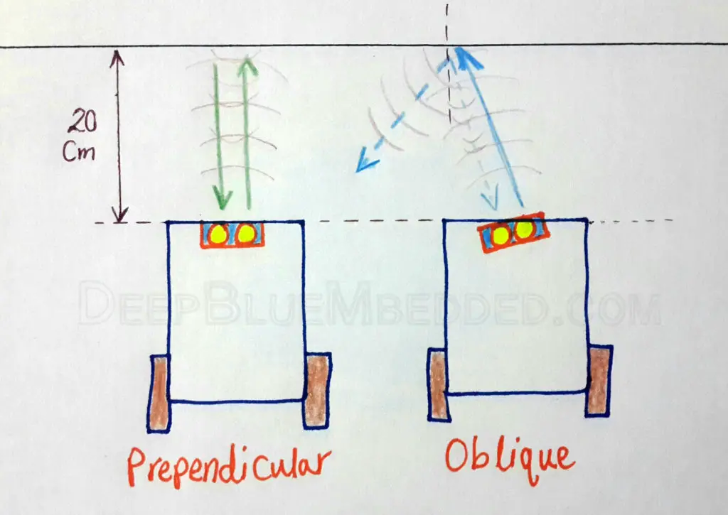
The distance between each of them and the wall is the same, say 20cm. The one on the left will be reading nearly 20cm. But the one on the right will have a reading that ranges from (25 to 100), you know what? it might even exceed the 4meters limit at some points! Why does this happen?
Well, the robot on the right is transmitting an ultrasound wave that is oblique to the wall. That’s why there is an angle of incidence, hence the reflected portion of the wave might be so weak to be considered which will be a miss. If it has reflected (by luck or more specifically by the nature of the surface material), then it may have taken a much longer time. So it’ll give you arbitrarily higher measurements.
Which means the sensor will fail. Just make sure that you’re fixing the sensor in the right position & orientation in the machine, device or the robot that you’re building to avoid a lot of hassle as much as possible.
3
Timer Module Won’t Overflow
We are using the Timer1 module to calculate the time period of the echo pulse, right?
What if the sensor is reading a very long distance? wouldn’t it be generating a very wide echo signal? would it cause the timer to overflow?
Well, before answering this question, I’m willing to bring you with me to think of what would really happen if the timer has reached overflow?
It’ll roll-over to zero again and start counting from zero. Which means at the end of the day, the value of TMR1 which we were using for distance calculation will now make no sense! Converting this value using the following formula will generate the wrong answer
The solution to this problem is by creating a flag and carefully set & clear it within your firmware. To help you keep track of the timer overflow behavior and perform the required modifications to the previous formula.
Enough of theory! XD
This situation will never happen under any circumstances. However, it might rarely happen for a different hardware (sensor + embedded computer) settings. But we’ll not be discussing that here. Let’s formulate our problem mathematically!
The upper limit for our HC-SR04 sensor is typically 4m. Using the speed formula (speed = distance / time), and substituting for (speed=340m/s & distance=4m). The result will be the maximum time period for an output echo pulse. Which will be nearly 11ms
If you still remembering, the Toverflow of our Timer1 module (for 4MHz osc & 1:1 PS) is nearly 65ms. Which is too way larger than the largest echo signal we could possibly have! So it turns out to be not that kind of a big deal.
4
Interrupts Effect
Let’s bring back the echo signal measuring procedure. I’ll only mention the lines of code that are involved in this process.
|
1 2 3 4 |
while(echo); TMR1ON = 1; while(!echo); TMR1ON = 0; |
You should remember this part of the code. In which we’re detecting a high signal on the echo pin and starting the Timer1 module. After that step, we’ll be waiting for the echo line to go down to low in order to indicate the echo pulse termination in order to stop the timer.
Well, we are assuming that during that waiting loop “while(!echo)” we won’t have any interruption in the pulse-width measurement process. And that’s not true!
The system can possibly get interrupted while measuring the echo pulse. The while(!echo) loop will be suspended until an arbitrary interrupt is serviced and then the controller will get back to that polling loop to find out that the echo line has already gone low while we’re handling the interruption!
Would it be a problem? well, an average interrupt handling routine might take up to 30 machine (clock) cycles. It may not sound that much for many of us but let’s do the math to figure it out!
For a system running @ 1MHz, The single clock period will be 1µs. Thus the 30 machine cycles will cost us exactly 30µs. Well, a 30µs increase in the measured echo time may not seem that much of time. But let’s also do the math of it!
Using the speed formula (speed = distance/time), substitute for (speed=340m/s & time=30µs). The error in distance will be about 1cm. It’s a small error indeed but it actually gets larger for smaller systems running at lower clock rates.
Obviously, this error gets dramatically smaller by increasing the clock rate up to 16 or 20MHz. It’ll be completely negligible!
However, if you’re willing to solve such a problem and secure your system as much as possible, you can disable the interrupts temporarily by clearing the GIE bit until the measurement process is successful then re-enable it once again. The modifications in the C-Code firmware will be as follows.
|
1 2 3 4 5 6 7 8 9 10 11 12 13 14 15 16 17 18 19 20 21 22 |
int calc_dist(void) { int distance=0; TMR1=0; // Send Trigger Pulse To The Sensor trigger=1; __delay_us(10); trigger=0; // Wait For The Echo Pulse From The Sensor while(!echo); // Turn ON Timer Module & Disable Interrupts GIE = 0; TMR1ON=1; // Wait Until The Pulse Ends while(echo); // Turn OFF The Timer & Re-Enable The Interrupts TMR1ON=0; GIE = 1; // Calculate The Distance Using The Equation distance=TMR1/58.82; return distance; } |
| Note | |||
|
Disabling the interrupts even for very short periods may not be an option for some special sort of systems. So be careful before considering this technique! |
|||
I hope you’ve enjoyed this tutorial and/or learned something new. If you find it really helpful, Then share it with your network or wherever it seems relevant & beneficial to others (e.g. Facebook groups, LinkedIn, etc). And let me know in the comments if I’ve missed something or if you’ve any further questions.
Good Luck and see you in the next tutorial ^^
| Previous Tutorial | Tutorial 12 | Next Tutorial | |||||
Bro, can u kindly clarify distance equation,
Thnx in advance
please give me a program code because i have find some error in this program so i want complete program of this project so pls help me
Can you tell me more specifically what are the problems you have?
The code listing in this tutorial behaves as shown in the video. I need to know what are you doing to be able to give some help.
Hello. How should i write a code if i only need to turn LED when sensors finds an obstacle. By the way i’m using 2 sensors.
Hi there, I would like to implement this project for myself because I find this very interesting. I’m just having trouble with implementing the code with my own device. I am a bit lost on where the full code listing is for lab 9 as it was stated that it was it in an attachment at the end of the tutorial. Could you show me the full code listing for lab 9?
Many thanks
Hi did you get the full code
Hi. Im currently studying PIC microcontroller 16F877A to be exact and your explanations here are really helpful and informative! I will finish this series and will keep waiting for updates. I really appreciate this. Thankyou!
It’s My Pleasure ^^ .. Wish You Best of Luck!
What is the meaning of while(!echo) statement in the code?I searched but could not find a definite answer.
while(!echo);
// Turn ON Timer Module
TMR1ON=1;
// Wait Until The Pulse Ends
while(echo);
// Turn OFF The Timer
TMR1ON=0;
Shouldn’t be this code opposite.I mean the while (!echo) should be at the bottom and while(echo) should be at the top of code which means like this;
while(echo);
// Turn ON Timer Module
TMR1ON=1;
// Wait Until The Pulse Ends
while(!echo);
// Turn OFF The Timer
TMR1ON=0;
Hi Khaled Magdy, thanks so much for doing this fantastic project. I would like to implement this project and I’m wondering what compiler and language did you use for this project? Can you please let me know? Thanks again!
while(!echo);
// Turn ON Timer Module
TMR1ON=1;
// Wait Until The Pulse Ends
while(echo);
// Turn OFF The Timer
TMR1ON=0;
Shouldn’t be this code opposite.I mean the while (!echo) should be at the bottom and while(echo) should be at the top of code which means like this;
while(echo);
// Turn ON Timer Module
TMR1ON=1;
// Wait Until The Pulse Ends
while(!echo);
// Turn OFF The Timer
TMR1ON=0;
Here we’re polling the echo pin. Which means the cpu is waiting while it’s LOW until a rising edge is received, then we start the timer and poll for the other edge and get the pulse width time. Which will be converted to distance in cm later on.
why do you divide by 5? dist = calc_dist()/5;
I did that because the application we’re building in this lab is to turn ON one LED for each 5 cm in distance. If distance is 10cm or more, 2 leds shouls be ON. If distance is 15 or more, 3 leds should be ON.
And so on… i hope it’s clear to you now
Regards ^^
This website is superb, thanks for this wonderful write ups. Please keep on writing I really enyoyed every chapter..
For those who wanted the full code, enjoy!
#include
#define _XTAL_FREQ 4000000
#define trigger RC2
#define echo RC3
#define B0 RB0
#define B1 RB1
#define B2 RB2
#define B3 RB3
int calc_dist(void); // Function Declaration
void delay(int a) //delay routine
{
unsigned int i,j;
for(i=0;i
for(j=0;j
}
void main(void)
{
// Configure The IO Pins
TRISB1 = 0;
TRISB2 = 1;
// — [[ Configure Timer1 To Operate In Timer Mode ]] —
// Clear The Timer1 Register. To start counting from 0
TMR1 = 0;
// Choose the local clock source (timer mode)
TMR1CS = 0;
// Choose the desired prescaler ratio (1:1)
T1CKPS0 = 0;
T1CKPS1 = 0;
// Create Distance Variable
int dist=0;
//–[ Configure The IO Pins ]–
// Set PORTB To Be Output Port (All The 8 Pins)
TRISB = 0x00;
// Set PORTB To Be LOW For initial State
PORTB = 0x00;
// Set RC2 To Be Output Pin ( Trigger )
TRISC2 = 0;
RC2 = 0;
// Set RC3 To Be Input Pin ( Echo )
TRISC3 = 1;
//–[ Configure Timer Module To Operate in Timer Mode ]–
// Clear The Pre-Scaler Select Bits
// T1CKPS0=0;
// T1CKPS1=0;
// Choose The Local Clock As Clock Source
// TMR1CS=0;
// Write The System’s Main Routine !
while(1)
{
dist = calc_dist()/5;
if(dist
{
B0=1;
B1=1;
B2=1;
B3=1;
}
else if(dist
{
B0=0;
B1=1;
B2=1;
B3=1;
}
else if(dist
{
B0=0;
B1=0;
B2=1;
B3=1;
}
else if(dist
{
B0=0;
B1=0;
B2=0;
B3=1;
}
else
{
PORTB = 0x00;
}
}
return;
}
// Definition Of The calc_dist() Function
int calc_dist(void)
{
int distance=0;
TMR1=0;
// Send Trigger Pulse To The Sensor
trigger=1;
delay(100);
trigger=0;
// Wait For The Echo Pulse From The Sensor
while(!echo);
// Turn ON Timer Module
TMR1ON=1;
// Wait Until The Pulse Ends
while(echo);
// Turn OFF The Timer
TMR1ON=0;
// Calculate The Distance Using The Equation
distance=TMR1/58.82;
return distance;
}