| Previous Tutorial | Tutorial 28 | Next Tutorial | |||||
| Interfacing I2C LCD With PIC MCUs | |||||||
| Intermediate Level ★★☆☆☆ | |||||||
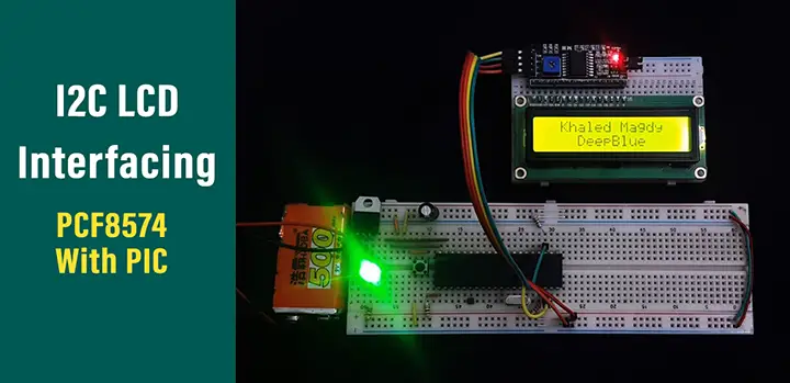
In this tutorial, you’ll learn how to interface alphanumeric LCD using I2C io expander PCF8574 and PIC microcontrollers. This will enable you to add up to 8 LCDs to your project and control them all using a single microcontroller and 2-wires only (2 IO pins for I2C).
The information included here can be easily transferred to different systems built around different microcontrollers (e.g. AVR, STM32, etc). The only prerequisite for this tutorial is the previous I2C Tutorial (check it out!).
[toc]
Components Needed For This Tutorial
| Qty. | Component Name | Buy On Amazon.com |
| 1 | PIC16F877A or PIC18F2550 or any other | Add |
| 2 | BreadBoard | Add |
| 1 | Alphanumeric LCD 16×2 | Add |
| 1 | I2C LCD IO Expander Module | Add |
| 8 | LED | Add Add |
| 1 | Resistors Kit | Add Add |
| 1 | Capacitors Kit | Add Add |
| 1 | Jumper Wires Pack | Add Add |
| 1 | LM7805 Voltage Regulator (5v) | Add |
| 1 | Crystal Oscillator | Add |
| 1 | PICkit2 or 3 Programmer | Add |
| 1 | 9v Battery or DC Power Supply | Add Add Add |
Debugging Tools:
- Digital Storage Oscilloscope (DSO): Siglent SDS1104 (on Amazon.com)
- Logic Analyzer (on Amazon.com)
I2C LCD IO Expander (PCF8574)
Module Board Description & Pinout
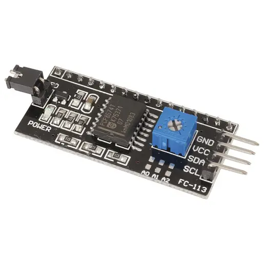
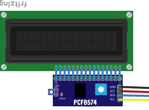
This module board is a breakout board for the I2C IO Expander chip PCF8574 designed for LCD interfacing via a 16-pin header. There is a jumper to whether turn on or off the LCD backlight. As well as a potentiometer to adjust the LCD screen contrast.
With solder pads, A0 A1 A2 which if left as is will be 1 1 1 (pulled-up). You can solder any bit of them to make it 0 if needed to address more than LCD I2C expander board. The board has a power indicator as well as a voltage regulator and most importantly a header to connect your I2C 2-wires (SCL, SDA).
Down below is the pin mapping and connection for this breakout board.
| 1 | Vss | |
| 2 | VDD | |
| 3 | Vo | |
| 4 | RS | P0 |
| 5 | R/W | P1 |
| 6 | EN | P2 |
| 7 | D0 | |
| 8 | D1 | |
| 9 | D2 | |
| 10 | D3 | |
| 11 | D4 | P4 |
| 12 | D5 | P5 |
| 13 | D6 | P6 |
| 14 | D7 | P7 |
| 15 | A / LED+ | P3 |
| 16 | K / LED- |
I2C IO Expander PCF8574
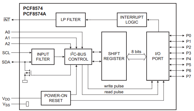
The PCF8574/74A provides general-purpose remote I/O expansion via the two-wire bidirectional I2C-bus (serial clock (SCL), serial data (SDA)) @ 100kHz. The system master can read from the input port or write to the output port through a single register.
The PCF8574 and PCF8574A are identical, except for the different fixed portion of the slave address. The three hardware address pins allow eight of each device to be on the same I2C-bus, so there can be up to 16 of these I/O expanders PCF8574/74A together on the same I2C-bus, supporting up to 128 I/Os (for example, 128 LEDs).
The active LOW open-drain interrupt output (INT) can be connected to the interrupt logic of the microcontroller and is activated when any input state differs from its corresponding input port register state. It is used to indicate to the microcontroller that an input state has changed and the device needs to be interrogated without the microcontroller continuously polling the input register via the I2C-bus.
Features of PCF8574
- I2C-bus to parallel port expander
- 100 kHz I2C-bus interface (Standard-mode I2C-bus)
- Operating supply voltage 2.5 V to 6 V with non-overvoltage tolerant I/O held to VDD with 100 uA current source
- 8-bit remote I/O pins that default to inputs at power-up
- Latched outputs directly drive LEDs
- Total package sink capability of 80 mA
- Active-LOW open-drain interrupt output
- Eight programmable slave addresses using three address pins
- Low standby current (2.5 uA typical)
Applications For PCF8574
- LEDs and displays
- Servers
- Keypads
- Industrial control
- Medical equipment
- PLC
- Cellular telephones
- Mobile devices
- Gaming machines
- Instrumentation and test measurement
Block Diagram
I2C Device Address
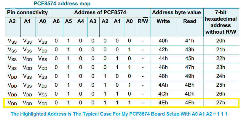
Following a START condition, the bus master must send the address of the slave it is accessing and the operation it wants to perform (read or write). The address format of the PCF8574/74A is shown down below. Slave address pins A2, A1 and A0 are held HIGH or LOW to choose one of eight slave addresses. To conserve power, no internal pull-up resistors are incorporated on A2, A1 or A0, so they must be externally held HIGH or LOW. The address pins (A2, A1, A0) can connect to VDD or VSS directly or through resistors.

The last bit of the first byte defines the operation to be performed. When set to logic 1 a read is selected, while a logic 0 selects a write operation.
The PCF8574 and PCF8574A are functionally the same. But they have a different fixed portion (A6 to A3) of the slave address. This allows eight of the PCF8574 and eight of the PCF8574A to be on the same I2C-bus without address conflict.
IO Programming
Quasi-Bidirectional I/Os
A quasi-bidirectional I/O is an input or output port without using a direction control register. Whenever the master reads the register, the value returned to the master depends on the actual voltage or status of the pin. At power-on, all the ports are HIGH with a weak 100 uA internal pull-up to VDD but can be driven LOW by an internal transistor, or an external signal. The I/O ports are entirely independent of each other, but each I/O octal is controlled by the same read or write data byte.
Writing To The Port (Output Mode)
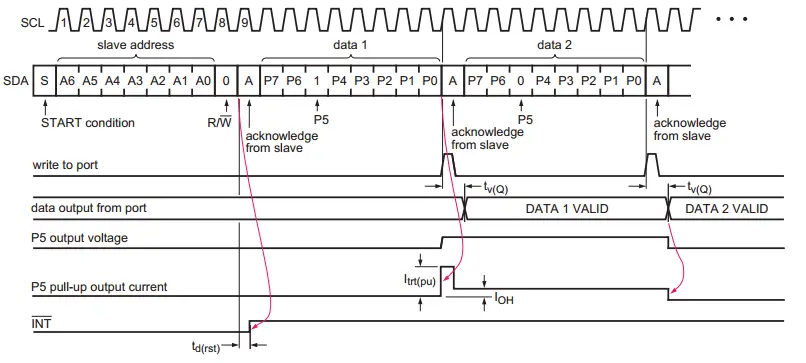
The master (microcontroller) sends the START condition and slave address setting the last bit of the address byte to logic 0 for the write mode. The PCF8574/74A acknowledges and the master then sends the data byte for P7 to P0 to the port register. As the clock line goes HIGH, the 8-bit data is presented on the port lines after it has been acknowledged by the PCF8574/74A. If a LOW is written, the strong pull-down turns on and stays on. If a HIGH is written, the strong pull-up turns on for 0.5 of the clock cycle, then the line is held HIGH by the weak current source. The master can then send a STOP or ReSTART condition or continue sending data. The number of data bytes that can be sent successively is not limited and the previous data is overwritten every time a data byte has been sent and acknowledged.
Reading from a port (Input mode)
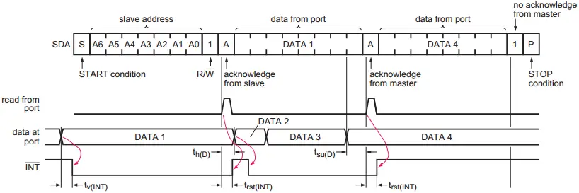
The port must have been previously written to logic 1, which is the condition after power-on reset. To enter the Read mode the master (microcontroller) addresses the slave device and sets the last bit of the address byte to logic 1 (address byte read).
The slave will acknowledge and then send the data byte to the master. The master will NACK and then send the STOP condition or ACK and read the input register again. The read of any pin being used as an output will indicate HIGH or LOW depending on the actual state of the pin.
If the data on the input port changes faster than the master can read, this data may be lost. For the following example diagram, DATA2 and DATA3 are lost because these data did not meet the setup time and hold time.
I2C LCD Interfacing With PCF8574
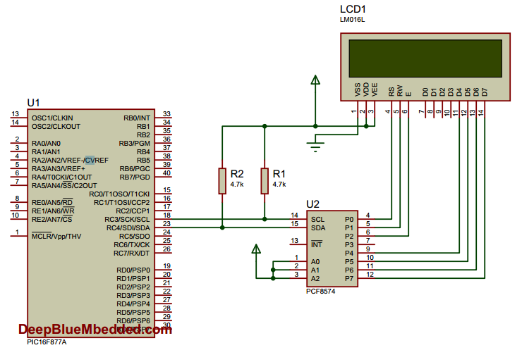
Connection Diagram (Hardware)
Driver Sub-Routines (Software Components)
In a previous tutorial (LCD Interfacing Tutorial), I’ve discussed how to properly initialize the LCD module. And how to move the cursor, write characters, write strings, clear the display, shift the entire display, etc. We’ll need these pieces of information once again in fact, so make sure to revisit the previous LCD Interfacing Tutorial.
Down below are the required basic software components (sub-routines) for interfacing the I2C LCD using the PCF8574 IO Expander.
I2C Driver Functions
*We’ve Developed These Functions In The Previous I2C Tutorial*
|
1 2 3 4 5 6 7 8 9 10 11 |
//---[ I2C Routines ]--- void I2C_Master_Init(const unsigned long baud); void I2C_Master_Wait(); void I2C_Master_Start(); void I2C_Master_RepeatedStart(); void I2C_Master_Stop(); void I2C_ACK(); void I2C_NACK(); unsigned char I2C_Master_Write(unsigned char data); unsigned char I2C_Read_Byte(void); |
LCD Driver Functions
Those are the functions we’ll create in this tutorial in the next section
|
1 2 3 4 5 6 7 8 9 10 11 12 13 14 |
//---[ LCD Routines ]--- void LCD_Init(unsigned char I2C_Add); void IO_Expander_Write(unsigned char Data); void LCD_Write_4Bit(unsigned char Nibble); void LCD_CMD(unsigned char CMD); void LCD_Set_Cursor(unsigned char ROW, unsigned char COL); void LCD_Write_Char(char); void LCD_Write_String(char*); void Backlight(); void noBacklight(); void LCD_SR(); void LCD_SL(); void LCD_Clear(); |
LCD Commands & Instructions
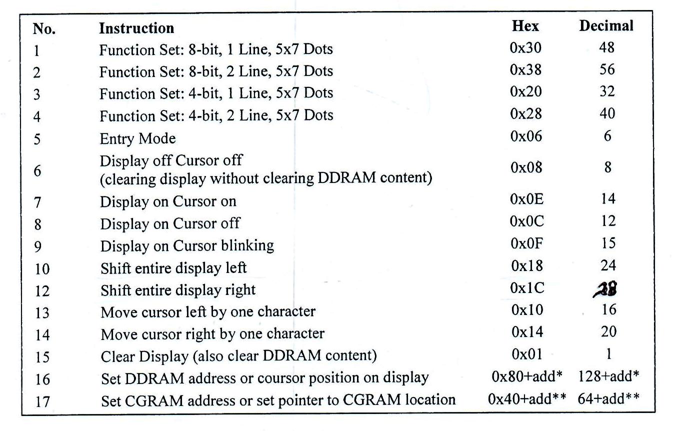
Implementing I2C LCD Driver Code
I2C_LCD.h Header File
|
1 2 3 4 5 6 7 8 9 10 11 12 13 14 15 16 17 18 19 20 21 22 23 24 25 26 27 28 29 30 31 32 33 34 35 36 37 38 39 40 41 42 43 44 45 46 47 48 49 50 51 52 53 54 55 56 |
/* File: I2C_LCD.h */ #define _XTAL_FREQ 16000000 #define I2C_BaudRate 100000 #define SCL_D TRISC3 #define SDA_D TRISC4 #define LCD_BACKLIGHT 0x08 #define LCD_NOBACKLIGHT 0x00 #define LCD_FIRST_ROW 0x80 #define LCD_SECOND_ROW 0xC0 #define LCD_THIRD_ROW 0x94 #define LCD_FOURTH_ROW 0xD4 #define LCD_CLEAR 0x01 #define LCD_RETURN_HOME 0x02 #define LCD_ENTRY_MODE_SET 0x04 #define LCD_CURSOR_OFF 0x0C #define LCD_UNDERLINE_ON 0x0E #define LCD_BLINK_CURSOR_ON 0x0F #define LCD_MOVE_CURSOR_LEFT 0x10 #define LCD_MOVE_CURSOR_RIGHT 0x14 #define LCD_TURN_ON 0x0C #define LCD_TURN_OFF 0x08 #define LCD_SHIFT_LEFT 0x18 #define LCD_SHIFT_RIGHT 0x1E #define LCD_TYPE 2 // 0 -> 5x7 | 1 -> 5x10 | 2 -> 2 lines //-----------[ Functions' Prototypes ]-------------- //---[ I2C Routines ]--- void I2C_Master_Init(); void I2C_Master_Wait(); void I2C_Master_Start(); void I2C_Master_RepeatedStart(); void I2C_Master_Stop(); void I2C_ACK(); void I2C_NACK(); unsigned char I2C_Master_Write(unsigned char data); unsigned char I2C_Read_Byte(void); //---[ LCD Routines ]--- void LCD_Init(unsigned char I2C_Add); void IO_Expander_Write(unsigned char Data); void LCD_Write_4Bit(unsigned char Nibble); void LCD_CMD(unsigned char CMD); void LCD_Set_Cursor(unsigned char ROW, unsigned char COL); void LCD_Write_Char(char); void LCD_Write_String(char*); void Backlight(); void noBacklight(); void LCD_SR(); void LCD_SL(); void LCD_Clear(); |
I2C_LCD.c Source File
|
1 2 3 4 5 6 7 8 9 10 11 12 13 14 15 16 17 18 19 20 21 22 23 24 25 26 27 28 29 30 31 32 33 34 35 36 37 38 39 40 41 42 43 44 45 46 47 48 49 50 51 52 53 54 55 56 57 58 59 60 61 62 63 64 65 66 67 68 69 70 71 72 73 74 75 76 77 78 79 80 81 82 83 84 85 86 87 88 89 90 91 92 93 94 95 96 97 98 99 100 101 102 103 104 105 106 107 108 109 110 111 112 113 114 115 116 117 118 119 120 121 122 123 124 125 126 127 128 129 130 131 132 133 134 135 136 137 138 139 140 141 142 143 144 145 146 147 148 149 150 151 152 153 154 155 156 157 158 159 160 161 162 163 164 165 166 167 168 169 170 171 172 173 174 175 176 177 178 179 180 181 182 183 184 185 186 |
#include <xc.h> #include "I2C_LCD.h" unsigned char RS, i2c_add, BackLight_State = LCD_BACKLIGHT; //---------------[ I2C Routines ]------------------- //-------------------------------------------------- void I2C_Master_Init() { SSPCON = 0x28; SSPCON2 = 0x00; SSPSTAT = 0x00; SSPADD = ((_XTAL_FREQ/4)/I2C_BaudRate) - 1; SCL_D = 1; SDA_D = 1; } void I2C_Master_Wait() { while ((SSPSTAT & 0x04) || (SSPCON2 & 0x1F)); } void I2C_Master_Start() { I2C_Master_Wait(); SEN = 1; } void I2C_Master_RepeatedStart() { I2C_Master_Wait(); RSEN = 1; } void I2C_Master_Stop() { I2C_Master_Wait(); PEN = 1; } void I2C_ACK(void) { ACKDT = 0; // 0 -> ACK I2C_Master_Wait(); ACKEN = 1; // Send ACK } void I2C_NACK(void) { ACKDT = 1; // 1 -> NACK I2C_Master_Wait(); ACKEN = 1; // Send NACK } unsigned char I2C_Master_Write(unsigned char data) { I2C_Master_Wait(); SSPBUF = data; while(!SSPIF); // Wait Until Completion SSPIF = 0; return ACKSTAT; } unsigned char I2C_Read_Byte(void) { //---[ Receive & Return A Byte ]--- I2C_Master_Wait(); RCEN = 1; // Enable & Start Reception while(!SSPIF); // Wait Until Completion SSPIF = 0; // Clear The Interrupt Flag Bit I2C_Master_Wait(); return SSPBUF; // Return The Received Byte } //====================================================== //---------------[ LCD Routines ]---------------- //----------------------------------------------- void LCD_Init(unsigned char I2C_Add) { i2c_add = I2C_Add; IO_Expander_Write(0x00); __delay_ms(30); LCD_CMD(0x03); __delay_ms(5); LCD_CMD(0x03); __delay_ms(5); LCD_CMD(0x03); __delay_ms(5); LCD_CMD(LCD_RETURN_HOME); __delay_ms(5); LCD_CMD(0x20 | (LCD_TYPE << 2)); __delay_ms(50); LCD_CMD(LCD_TURN_ON); __delay_ms(50); LCD_CMD(LCD_CLEAR); __delay_ms(50); LCD_CMD(LCD_ENTRY_MODE_SET | LCD_RETURN_HOME); __delay_ms(50); } void IO_Expander_Write(unsigned char Data) { I2C_Master_Start(); I2C_Master_Write(i2c_add); I2C_Master_Write(Data | BackLight_State); I2C_Master_Stop(); } void LCD_Write_4Bit(unsigned char Nibble) { // Get The RS Value To LSB OF Data Nibble |= RS; IO_Expander_Write(Nibble | 0x04); IO_Expander_Write(Nibble & 0xFB); __delay_us(50); } void LCD_CMD(unsigned char CMD) { RS = 0; // Command Register Select LCD_Write_4Bit(CMD & 0xF0); LCD_Write_4Bit((CMD << 4) & 0xF0); } void LCD_Write_Char(char Data) { RS = 1; // Data Register Select LCD_Write_4Bit(Data & 0xF0); LCD_Write_4Bit((Data << 4) & 0xF0); } void LCD_Write_String(char* Str) { for(int i=0; Str[i]!='\0'; i++) LCD_Write_Char(Str[i]); } void LCD_Set_Cursor(unsigned char ROW, unsigned char COL) { switch(ROW) { case 2: LCD_CMD(0xC0 + COL-1); break; case 3: LCD_CMD(0x94 + COL-1); break; case 4: LCD_CMD(0xD4 + COL-1); break; // Case 1 default: LCD_CMD(0x80 + COL-1); } } void Backlight() { BackLight_State = LCD_BACKLIGHT; IO_Expander_Write(0); } void noBacklight() { BackLight_State = LCD_NOBACKLIGHT; IO_Expander_Write(0); } void LCD_SL() { LCD_CMD(0x18); __delay_us(40); } void LCD_SR() { LCD_CMD(0x1C); __delay_us(40); } void LCD_Clear() { LCD_CMD(0x01); __delay_us(40); } |
main.c Source File (For Testing The I2C_LC Lib)
|
1 2 3 4 5 6 7 8 9 10 11 12 13 14 15 16 17 18 19 20 21 22 23 24 25 |
/* * File: main.c * Author: Khaled Magdy */ #include <xc.h> #include "config.h" #include "I2C_LCD.h" void main(void) { I2C_Master_Init(); LCD_Init(0x4E); // Initialize LCD module with I2C address = 0x4E LCD_Set_Cursor(1, 1); LCD_Write_String(" Khaled Magdy"); LCD_Set_Cursor(2, 1); LCD_Write_String(" DeepBlue"); while(1) { } return; } |
I2C LCD 16×2 Interfacing With PIC – LAB
| Lab Name | I2C LCD Interfacing |
| Lab Number | 34 |
| Lab Level | Intermediate |
| Lab Objectives | Learn how to use I2C Communication works. And interface the I2C LCD IO Expander Module (PCF8574) And Initialize Your LCD, Write Characters, String, Set The Cursor Position, Shift The Entire Display, and Clear The Display. And More… |
1. Coding
Open the MPLAB IDE and create a new project and name it “I2C_LCD”. If you have some issues doing so, you can always refer to the previous tutorial using the link below.
Set the configuration bits to match the generic setting which we’ve stated earlier. And if you also find troubles creating this file, you can always refer to the previous tutorial using the link below.
Now, open the main.c file and let’s start developing the firmware for our project.
Start your project by including the I2C_LCD.h driver library which we’ve developed earlier in this tutorial. Then Initialize the I2C LCD IO Expander @ The I2C_Address For Your Module (Typically A0 A1 A2 = 1 1 1).
The Full Code Listing For This Lab
|
1 2 3 4 5 6 7 8 9 10 11 12 13 14 15 16 17 18 19 20 21 22 23 24 25 26 27 28 29 30 31 32 33 34 |
/* * File: main.c * Author: Khaled Magdy * LAB: 34 - I2C LCD Interfacing */ #include <xc.h> #include "config.h" #include "I2C_LCD.h" void main(void) { I2C_Master_Init(); LCD_Init(0x4E); // Initialize LCD module with I2C address = 0x4E LCD_Set_Cursor(1, 1); LCD_Write_String(" Khaled Magdy"); LCD_Set_Cursor(2, 1); LCD_Write_String(" DeepBlue"); __delay_ms(2500); while(1) { LCD_SR(); __delay_ms(350); LCD_SR(); __delay_ms(350); LCD_SL(); __delay_ms(350); LCD_SL(); __delay_ms(350); } return; } |
2. Simulation
Here are the simulation results.
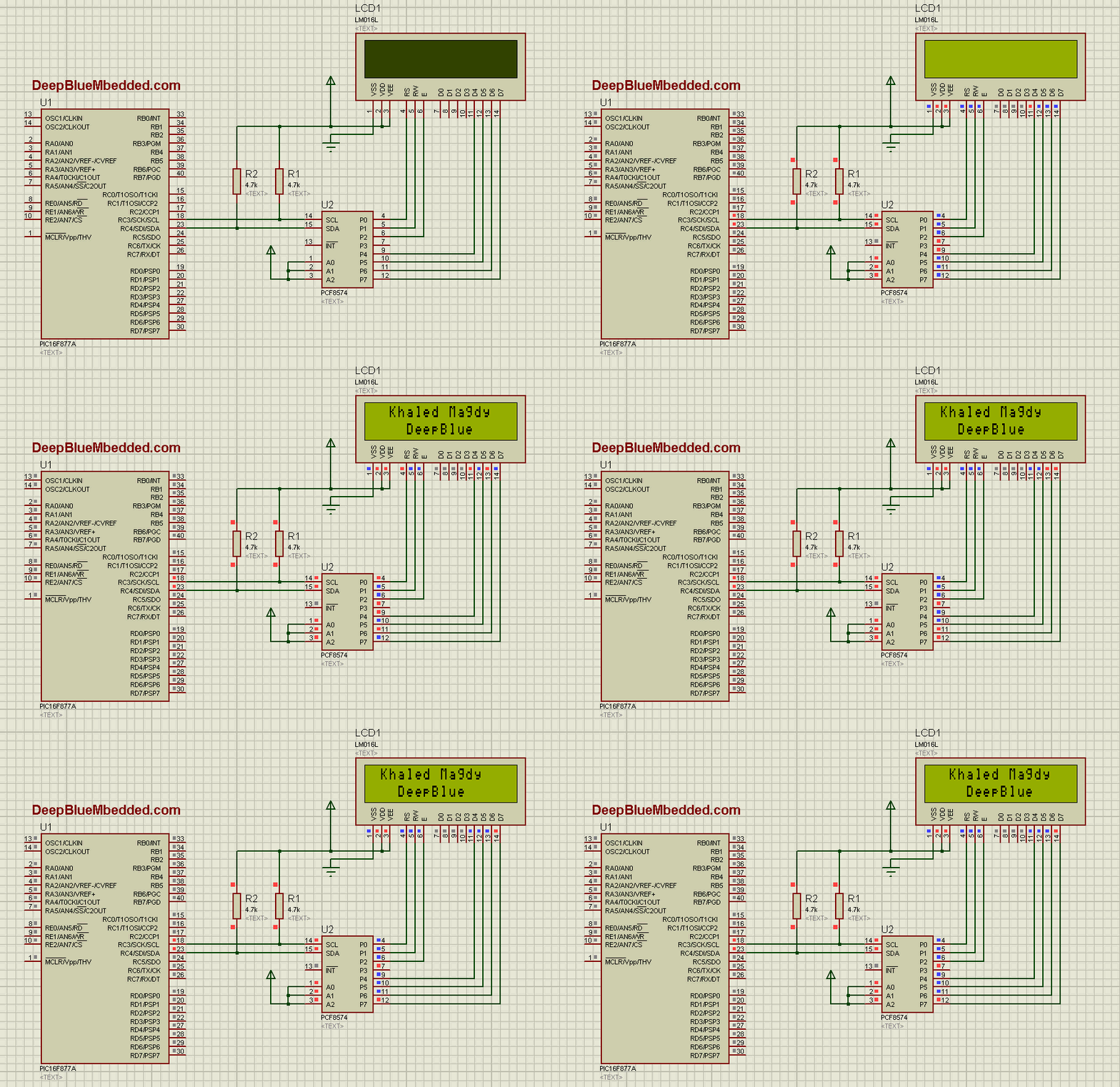
3. Prototyping
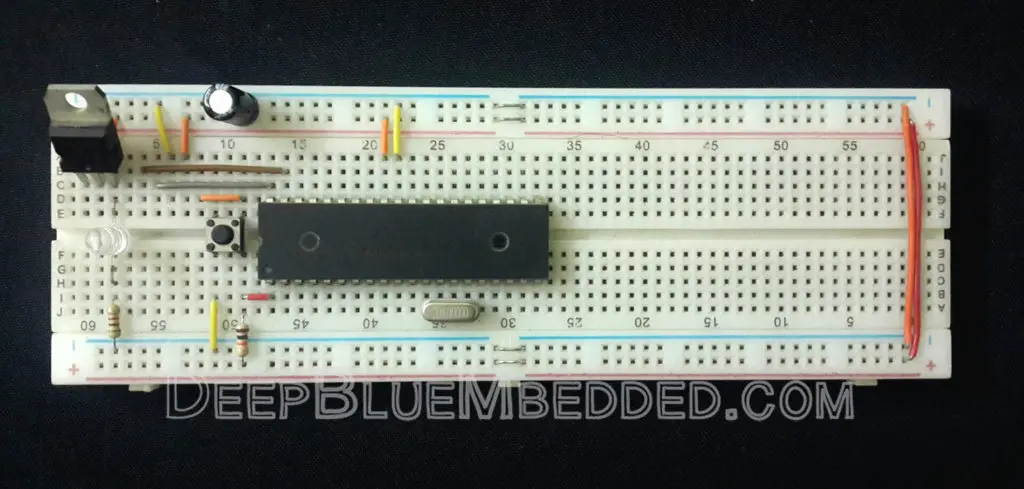
Down below is the real-life running test for this LAB on real boards. It’s very easy to hook everything up in this LAB. And it might be a little bit challenging to get it to work in case you MCU has different hardware implementation that needs a little bit of tweaking in code to get it to work well.
 |
Download I2C LC LAB Project (Code+Simulation)
Concluding Remarks
1
The IO Expander I2c Device Address
Double-Check the IC name and address and revise the datasheet to make sure what’s the i2c address for your module. And if you’re willing to hook up more than once, you’ll have to solder the pads on the module board. And make sure to use the correct address in the code! I’m pretty sure this will cause frustration in most of cases. So, please carefully check and set the i2c address!
2
Changing The LCD Type
I’ve shown you in the LAB prototyping short video that it’s possible to change the alphanumeric LCD type without even changing a single line of code. However, it’s not recommended to do so! You must read the datasheet and get all the configurations done correctly in order to have full control over what’s being displayed on the LCD.
3
More Than 1 MCU Can Write To The LCD
Using the I2C IO Expander and in this configuration, more than 1 MCU can actually write to the LCD (cooperatively). And you’ll be responsible for prioritizing and synchronizing this behavior in order to get it right. But all in all, it’s possible! More than a master can send their data to the LCD display (maybe at different rows, 1 for each? IDK, it’s your decision).
4
LCD Custom Character Generator Tool
You can also use the free tool down below to generate your own custom characters and symbols for the LCD display. Things like speaker icon, battery level indicator, and so on.
Custom LCD Character Generator Online Tool
| Previous Tutorial | Tutorial 28 | Next Tutorial | |||||


please post a tutorial for rtc interfacing with pic.
MPU6050 + HMC5883L Magnetometer + RTC all are on my to-do list for next upcoming tutorials.
Thanks for the suggestion and stay tuned!
Hey khaled.
What resistor value should be used for the open drain circuit ??
Also i read that the i2c module already as a pull up resistor integrated knside ? Whays the need for an external one ??
Thanks ????
Greetings ^^
Hmmm. It actually depends and mainly on the i2c bus speed and total capacitance that limit our resistor choice. High speed communication requires less resistance and vice versa. Exact numbers are to be calculated for each system case by case. No exact figures for all senarios.
That’s right but not all i2c devices has internal pull ups. It can be used for sure if it does exist and its value matches the needed resistance, then why not
Many modules and sensors that use i2c protocol come with pull ups on board so you don’t actually need to add them yourself in these cases.
One extra clarification if you dont mind ????
why on earth does the I2C expander have pins connected to D0-D3 of the LCD if the D4-D7 are the only LCD pins addressable by the I2C expander board ??
Hello Msameh ^^
I think it’s the way they’ve chosen while designing this module board XD. The chip gives you 8 pins as expansion which you can control over the i2c bus. 4 of which are for data (p4-p7) for lcd pins (d4-d7). And a couple of control signal. Everything can be flipped arround unless it’s actually soldered on the module board. So it’s as it’s! Hope this helps ^^
The only reasons I could think of is that they are used for reading and they are used for interfacing in 8bit (i totally overlooked that xP)
Thanks anyways ❤
Thanks Khaled, It worked for me. But i can’t download your project file. I have just copied form blog. I am using it for dsPic33EP series
Hi Khaled
I am currently doing a project with a 16×2 LCD, I2C PCF 8574A and a PIC 16F877A.
The example of your page is with the I2C PCF8574, in the simulation in Proteus it does not work with the I2C model that I am using.
I understand it is time to change the address of the I2C in the code
But I can’t find in which line of the code the I2C address is changed.
Apparently the address is 0x3F.
I appreciate a prompt response
Excellent job! ???? I adapt this on CCS texas instruments on tiva tm4c1294xl and it worked, I will upload my code later as you do, the functions could fit nicely, I only have to adapt I2C routines to your code, nice done!
Great job Pablo! I’ll be also adapting this to the STM32 and will upload it in the next few weeks or so. I expect it to work well and will try to refine the new version so it can be more generic and portable.
Drear Engineer Khaled Magdy
I would like to thank you for your great tutorials , I would like to contact by email regards an embedded project if you agree please share your email.
I also need to know if you offer a privet tutorials.
thanks
Khaled.
Do you have example files for PIC18 series? In particular I am looking for PIC18F14K50 . Thanks
Thank you so much for creating this site! It has greatly helped me get up and running with PICs.
Thank You so much for your Tutorials
Glad you found it helpful!