| Previous Tutorial | Tutorial 23 | Next Tutorial | |||||
| LM35 Temperature Sensor Interfacing | |||||||
| Introductory Level ★☆☆☆☆ | |||||||
In this tutorial, we’ll discuss how to interface the LM35 temperature sensor with a PIC microcontroller. Using the ADC to get the analog output voltage of the sensor then converting it back to Celsius degrees, and finally display the result on an LCD and also send it via serial port to a host PC to monitor the temperature remotely. So, let’s get started!
[toc]
Required Components
| Qty. | Component Name | Buy On Amazon.com |
| 1 | PIC16F877A | Add |
| 1 | BreadBoard | Add |
| 1 | LM35 Sensor | Add |
| 1 | Alphanumeric LCD 16×2 | Add |
| 1 | USB-TTL (FTDI) Serial Converter | Add |
| 1 | Jumper Wires Pack | Add Add |
| 1 | LM7805 Voltage Regulator (5v) | Add |
| 1 | 4MHz Crystal Oscillator | Add |
| 1 | PICkit2 or 3 Programmer | Add |
LM35 Temperature Sensor
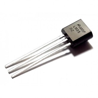
The LM35 is a temperature sensor widely used in electronic projects and midrange devices. It has limited usage in industrial applications due to maximum temperature range limitations. It’s rated to a full range of −55°C to 150°C. You can just power it up and instantly read the voltage level on the output terminal. The Vout of the sensor directly maps to the sensor’s temperature as we’ll see hereafter.
Features
- Calibrated Directly in Celsius (Centigrade)
- Linear + 10-mV/°C Scale Factor
- 0.5°C Ensured Accuracy (at 25°C)
- Rated for Full −55°C to 150°C Range
- Low-Cost
- Operates From 4 V to 30 V
- Less Than 60-μA Current Drain
- Non-Linearity Only ±¼°C Typical
- Low-Impedance Output, 0.1 Ω for 1-mA Load
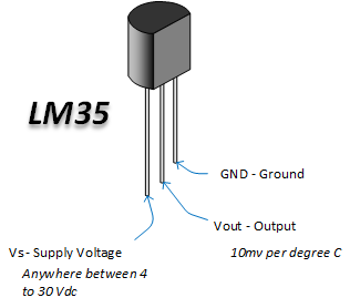
Pinout
V-T Characteristics
LM35 Transfer Function
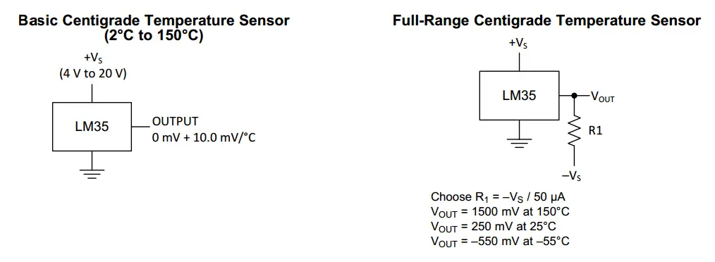
The accuracy specifications of the LM35 are given with respect to a simple linear transfer function:
VOUT = (10 mv / °C) × T
where VOUT is the LM35 output voltage & T is the temperature in °C
Typical Applications
- Low-Temperature Measurements
- Battery Charging Management
- Power Supply Monitoring
- Small Boilers
- HVAC
- And a variety of electronic projects
Alternatives For LM35
- Negative Temperature Coefficient (NTC) thermistor. The effective operating range is -50 to 250 °C.
- Resistance Temperature Detector (RTD), also known as a resistance thermometer. Platinum RTDs offer a fairly linear output that is highly accurate (0.1 to 1 °C) across -200 to 600 °C. While providing the greatest accuracy, RTDs also tend to be the most expensive of temperature sensors.
- Thermocouple. Thermocouples are nonlinear sensors, requiring conversion when used for temperature control and compensation, typically accomplished using a LUT (lookup table). Accuracy is low, from 0.5 °C to 5 °C. However, they operate across the widest temperature range, from -200 °C to 1750 °C.
Extracting Information From Analog Signal
Analog Sensors
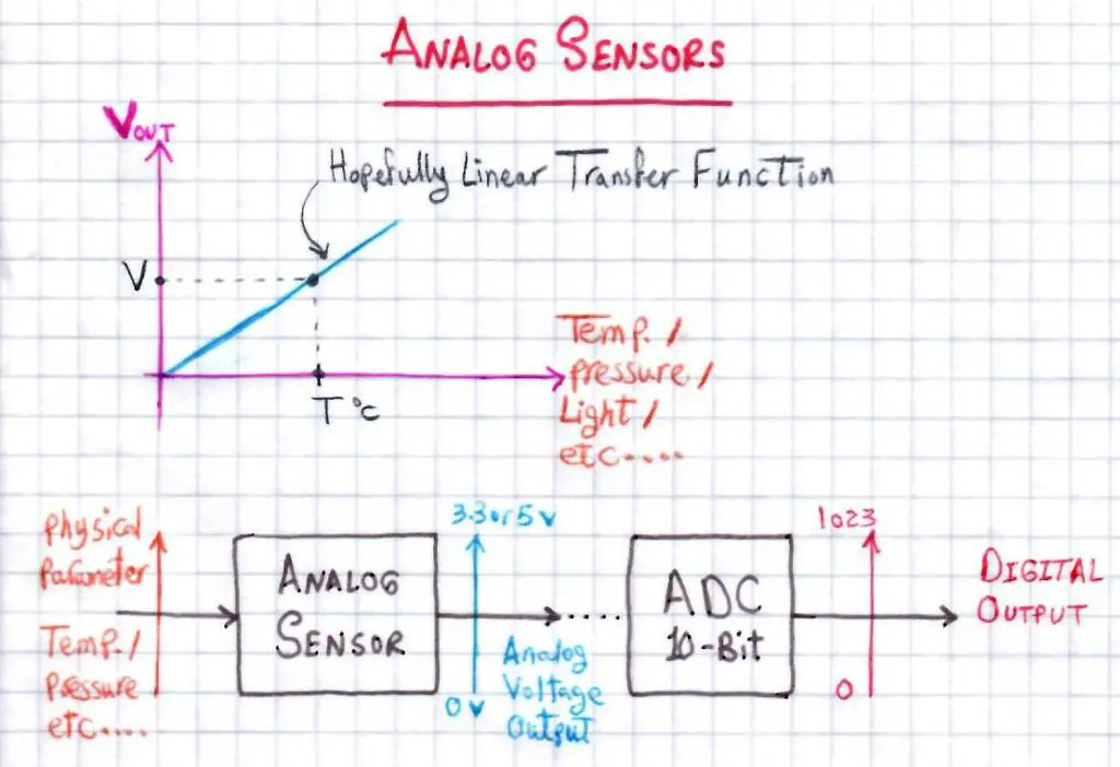
There is a variety of electronic sensors that produce an analog output instead of digital data that could be directly manipulated by our digital micro-computers (MCUs). The output is typically a low voltage signal (0->3.3 or 5v). Which directly maps to the physical parameter being measured by the sensor (e.g. Temperature, pressure, light intensity, sound level, etc).
Usually, the transfer functions of analog sensors are linear for easier calculations and more accurate results under operating conditions.
Using ADC
Reading an analog sensor involves using an ADC or A/D (Analog To Digital Converter). Which helps the microcontroller to evaluate the voltage level on an analog input pin and converters it to a digital value for further manipulations and storage.
<< Check Out The ADC Tutorial >>
There are many ways/schemes to read an ADC with your microcontroller. Every aspect of ADC is completely presented in the above tutorial, so check it out. Hereafter in this tutorial, we’ll be using a couple of functions which we’ve previously created. First of which, is the ADC initialization routine. And the other one initiates an A/D conversion and returns back the 10-Bit AD Result.
|
1 2 3 4 5 6 7 8 9 10 11 12 13 14 15 16 17 18 19 20 |
//------------[ AD Converter Routines ]-------------- void ADC_Init() { ADCON0 = 0x41; // Turn ADC ON, Select AN0 Channel, ADC Clock = Fosc/8 ADCON1 = 0x80; // All 8 Channels Are Analog, Result is "Right-Justified" // ADC Clock = Fosc/8 } uint16_t ADC_Read(uint8_t ANC) { if(ANC<0 || ANC>7) // Check Channel Number Validity { return 0;} ADCON0 &= 0x11000101; // Clear The Channel Selection Bits ADCON0 |= ANC<<3; // Select The Required Channel (ANC) // Wait The Aquisition Time __delay_us(30); // The Minimum Tacq = 20us, So That should be enough GO_DONE = 1; // Start A/D Conversion while(ADCON0bits.GO_DONE); // Polling GO_DONE Bit // Provides Delay Until Conversion Is Complete return ((ADRESH << 8) + ADRESL); // Return The Right-Justified 10-Bit Result } |
Result Conversion
The output of an ADC will be a digital (numeric) value stored in a memory register. Which means you’ll have to manipulate & convert this value to estimate the voltage level on the analog input pin. Therefore, you’ll be able to use the transfer function equation of your sensor to know the physical parameter real measurement. Whether it’s temperature, pressure, or light intensity, it’s all the same as seen by the processor.
Numeric Example
[Assuming 10-Bit ADC with Vref=5v and Temperature Sensor Transfer Function of 10mV/°C]
Let’s start with an A/D Result of 100
=> ADRES = 100
So, The Sensor’s Output Voltage (VOUT) is calculated as follows
=> ADC_Resolution = FSR/2^10 = 5v/1024 = 4.88mV
=> VOUT = ADC_Resolution x ADRES = 0.488Volts
Therefore, The Temperature Measured By The Sensor is as follows
=> Temperature = VOUT/10mV = 48.82°C
LM35 Temperature Sensor + LCD With PIC – LAB1
| Lab Name | LM35 Temperature Sensor Interfacing + LCD Display |
| Lab Number | 22 |
| Lab Level | Beginner |
| Lab Objectives | Learn how to configure The ADC Module and read analog signals. Interface The LM35 Temperature Sensor and print out the result on an alphanumeric LCD screen. |
1. Coding
Open the MPLAB IDE and create a new project name it “LM35_LCD”. If you have some issues doing so, you can always refer to the previous tutorial using the link below.
Set the configuration bits to match the generic setting which we’ve stated earlier. And if you also find troubles creating this file, you can always refer to the previous tutorial using the link below.
Now, open the main.c file and let’s start developing the firmware for our project.
The first task is to initialize the ADC module using the basic firmware drivers which we’ve already built previously. Then, we’ll read convert the voltage level on Analog Channel 0 and convert the 10-Bit A/D conversion result to temperature in Celsius and print it out to the LCD.
Here is the Full Code Listing For This LAB
|
1 2 3 4 5 6 7 8 9 10 11 12 13 14 15 16 17 18 19 20 21 22 23 24 25 26 27 28 29 30 31 32 33 34 35 36 37 38 39 40 41 42 43 44 45 46 47 48 49 50 51 52 53 54 55 56 57 58 59 60 61 62 63 64 65 66 67 68 69 70 71 72 73 74 75 76 77 78 79 80 81 82 83 84 85 86 87 88 89 90 91 92 93 94 95 96 97 98 99 100 101 102 103 104 105 106 107 108 109 110 111 112 113 114 115 116 117 118 119 120 121 122 123 124 125 126 127 128 129 130 131 132 133 134 135 136 137 138 139 140 141 142 143 144 145 146 147 148 149 150 151 152 153 154 155 156 157 158 159 160 161 162 163 164 165 166 167 168 169 170 171 172 173 174 175 176 177 178 179 180 181 182 183 184 185 186 |
/* * File: main.c * LAB: 22 * LAB Name: LM35 Temp. Sensor + LCD * Author: Khaled Magdy * Visit @ https://deepbluembedded.com */ #include <xc.h> #include "config.h" #include <stdint.h> #include <stdio.h> //================================= //--------[ Definitiotns ]--------- #define _XTAL_FREQ 4000000 #define LCD_EN_Delay 500 #define LCD_DATA_PORT_D TRISD #define LCD_RS_D TRISD2 #define LCD_EN_D TRISD1 #define RS RD2 #define EN RD1 #define D4 RD4 #define D5 RD5 #define D6 RD6 #define D7 RD7 //================================= //-----[ Globals ]----- uint16_t AN0RES=0; float Temperature, Voltage; char* line1 = " Temperature Is "; char* TempSTR[16]; //================================= //-----[ Functions Prototypes ]---- void ADC_Init(); uint16_t ADC_Read(uint8_t); void LCD_Init(); void LCD_Clear(); void LCD_CMD(char); void LCD_DATA(char); void LCD_Set_Cursor(char, char); void LCD_Write_Char(char); void LCD_Write_String(char*); //================================= //---------[ Main Routine]--------- void main(void) { LCD_Init(); LCD_Clear(); ADC_Init(); while(1) { // Read The ADC AN0RES = ADC_Read(0); // Read Analog Channel 0 // Calculate The Temperature Voltage = AN0RES * 0.0048828; Temperature = Voltage / 0.01; // Convert The Temperature From Float To String sprintf(TempSTR, " %.3fc", Temperature); // Print Out The Temperature LCD_Set_Cursor(1,1); LCD_Write_String(line1); LCD_Set_Cursor(2,1); LCD_Write_String(TempSTR); __delay_ms(10); } return; } //================================= //--------[ ADC Routines ]--------- void ADC_Init() { ADCON0 = 0x41; // Turn ADC ON, Select AN0 Channel, ADC Clock = Fosc/8 ADCON1 = 0x80; // All 8 Channels Are Analog, Result is "Right-Justified" // ADC Clock = Fosc/8 } uint16_t ADC_Read(uint8_t ANC) { if(ANC<0 || ANC>7) // Check Channel Number Validity { return 0;} ADCON0 &= 0x11000101; // Clear The Channel Selection Bits ADCON0 |= ANC<<3; // Select The Required Channel (ANC) // Wait The Aquisition Time __delay_us(30); // The Minimum Tacq = 20us, So That should be enough GO_DONE = 1; // Start A/D Conversion while(ADCON0bits.GO_DONE); // Polling GO_DONE Bit // Provides Delay Until Conversion Is Complete return ((ADRESH << 8) + ADRESL); // Return The Right-Justified 10-Bit Result } //================================= //--------[ LCD Routines ]--------- void LCD_DATA(char Data) { if(Data& 1) D4 = 1; else D4 = 0; if(Data& 2) D5 = 1; else D5 = 0; if(Data& 4) D6 = 1; else D6 = 0; if(Data& 8) D7 = 1; else D7 = 0; } void LCD_CMD(char a) { RS = 0; LCD_DATA(a); //Incoming Hex value EN = 1; __delay_ms(4); EN = 0; } void LCD_Clear() { LCD_CMD(0); //Clear the LCD LCD_CMD(1); //Move the cursor to first position } void LCD_Set_Cursor(char a, char b) { char Temp,z,y; if(a== 1) { Temp = 0x80 + b - 1; z = Temp>>4; //Lower 8-bits y = Temp & 0x0F; //Upper 8-bits LCD_CMD(z); //Set Row LCD_CMD(y); //Set Column } else if(a== 2) { Temp = 0xC0 + b - 1; z = Temp>>4; //Lower 8-bits y = Temp & 0x0F; //Upper 8-bits LCD_CMD(z); //Set Row LCD_CMD(y); //Set Column } } void LCD_Init() { // IO Pin Configurations LCD_DATA_PORT_D = 0x00; LCD_RS_D = 0; LCD_EN_D = 0; // The Procedure As Described in Datasheet LCD_DATA(0x00); __delay_us(LCD_EN_Delay); LCD_CMD(0x03); __delay_ms(5); LCD_CMD(0x03); __delay_ms(11); LCD_CMD(0x03); LCD_CMD(0x02); //Clears the RAM and initializes the LCD LCD_CMD(0x02); //Clears the RAM and initializes the LCD LCD_CMD(0x08); //Select Row 1 LCD_CMD(0x00); //Clear Row 1 Display LCD_CMD(0x0C); //Select Row 2 LCD_CMD(0x00); //Clear Row 2 Display LCD_CMD(0x06); } void LCD_Write_Char(char data) { char Lower_Nibble,Upper_Nibble; Lower_Nibble = data&0x0F; Upper_Nibble = data&0xF0; RS = 1; LCD_DATA(Upper_Nibble>>4); EN = 1; __delay_us(LCD_EN_Delay); EN = 0; __delay_us(LCD_EN_Delay); LCD_DATA(Lower_Nibble); EN = 1; __delay_us(LCD_EN_Delay); EN = 0; __delay_us(LCD_EN_Delay); } void LCD_Write_String(char *a) { int i; for(i=0;a[i]!='\0';i++) LCD_Write_Char(a[i]); } |
2. Simulation
Here is an animation for the running simulation tests.
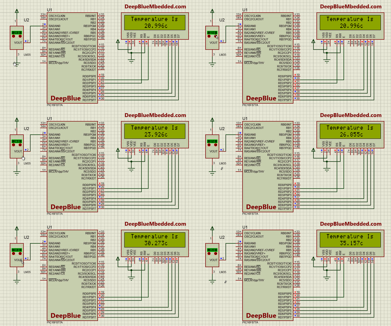
3. Prototyping
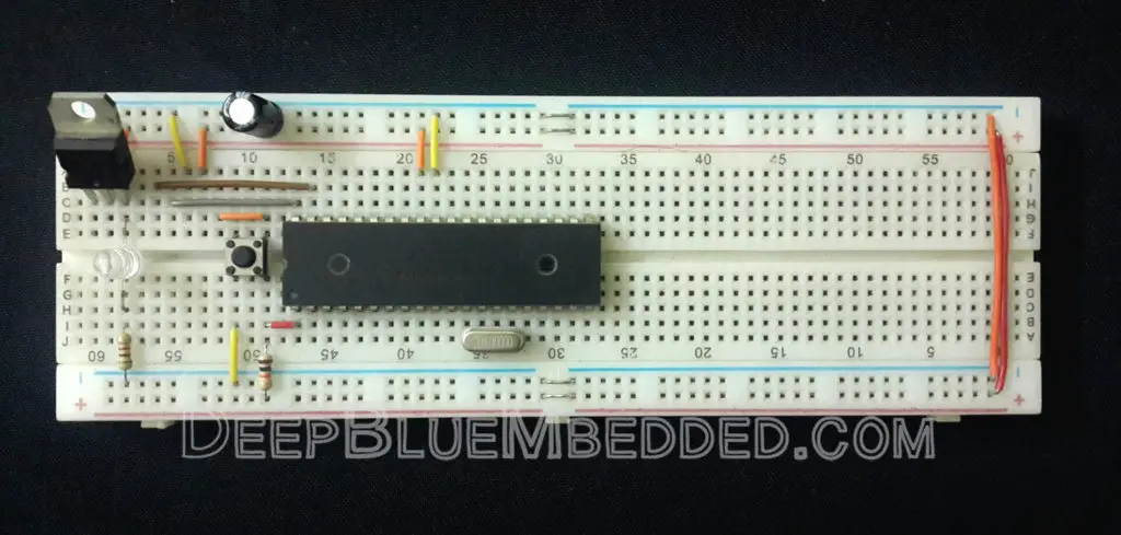
Wiring up this schematic on a breadboard should be an easy task. Just upload your firmware hex file to the microcontroller chip. And hook up the input power rails and start testing it up!
Here is a video for the final output of this LAB.
LM35 Temperature Sensor + Serial – LAB2
| Lab Name | LM35 Temperature Sensor Interfacing + Serial Monitor |
| Lab Number | 23 |
| Lab Level | Beginner |
| Lab Objectives | Learn how to configure The ADC Module and read analog signals. Interface The LM35 Temperature Sensor and print out the result to the serial monitor on your computer. |
1. Coding
Open the MPLAB IDE and create a new project name it “LM35_Serial”. If you have some issues doing so, you can always refer to the previous tutorial using the link below.
Set the configuration bits to match the generic setting which we’ve stated earlier. And if you also find troubles creating this file, you can always refer to the previous tutorial using the link below.
Now, open the main.c file and let’s start developing the firmware for our project.
The first task is to initialize the ADC module using the basic firmware drivers which we’ve already built previously. Then, we’ll read convert the voltage level on Analog Channel 0 and convert the 10-Bit A/D conversion result to temperature in Celsius and print it out to the serial monitor.
Here is the Full Code Listing For This LAB
|
1 2 3 4 5 6 7 8 9 10 11 12 13 14 15 16 17 18 19 20 21 22 23 24 25 26 27 28 29 30 31 32 33 34 35 36 37 38 39 40 41 42 43 44 45 46 47 48 49 50 51 52 53 54 55 56 57 58 59 60 61 62 63 64 65 66 67 68 69 70 71 72 73 74 75 76 77 78 79 80 81 82 83 84 85 86 87 88 89 90 91 92 93 94 95 |
/* * File: main.c * LAB: 23 * LAB Name: LM35 Temp. Sensor + Serial * Author: Khaled Magdy * Visit @ https://deepbluembedded.com */ #include <xc.h> #include "config.h" #include <stdint.h> #include <stdio.h> //================================= //--------[ Definitiotns ]--------- #define _XTAL_FREQ 4000000 #define Baud 9600 //================================= //-----[ Globals ]----- uint16_t AN0RES=0; float Temperature, Voltage; char* TempSTR[25]; //================================= //-----[ Functions Prototypes ]---- void ADC_Init(); uint16_t ADC_Read(uint8_t); void UART_TX_Init(void); void UART_Write(uint8_t); void UART_Write_String(char *); //================================= //---------[ Main Routine]--------- void main(void) { UART_TX_Init(); ADC_Init(); while(1) { // Read The ADC AN0RES = ADC_Read(0); // Read Analog Channel 0 // Calculate The Temperature Voltage = AN0RES * 0.0048828; Temperature = Voltage / 0.01; // Convert The Temperature From Float To String sprintf(TempSTR, "Temperature is -> %.3fc \r\n", Temperature); // Print Out The Temperature UART_Write_String(TempSTR); __delay_ms(10); } return; } //================================= //--------[ ADC Routines ]--------- void ADC_Init() { ADCON0 = 0x41; // Turn ADC ON, Select AN0 Channel, ADC Clock = Fosc/8 ADCON1 = 0x80; // All 8 Channels Are Analog, Result is "Right-Justified" // ADC Clock = Fosc/8 } uint16_t ADC_Read(uint8_t ANC) { if(ANC<0 || ANC>7) // Check Channel Number Validity { return 0;} ADCON0 &= 0x11000101; // Clear The Channel Selection Bits ADCON0 |= ANC<<3; // Select The Required Channel (ANC) // Wait The Aquisition Time __delay_us(30); // The Minimum Tacq = 20us, So That should be enough GO_DONE = 1; // Start A/D Conversion while(ADCON0bits.GO_DONE); // Polling GO_DONE Bit // Provides Delay Until Conversion Is Complete return ((ADRESH << 8) + ADRESL); // Return The Right-Justified 10-Bit Result } //================================= //--------[ UART Routines ]-------- void UART_TX_Init(void) { // Set Baud = 9600 BRGH = 1; SPBRG = 25; //Writing SPBRG Register //--[ Enable The Ascynchronous Serial Port ]-- SYNC = 0; SPEN = 1; //--[ Set The RX-TX Pins to be in UART mode (not io) ]-- TRISC6 = 1; // As stated in the datasheet TRISC7 = 1; // As stated in the datasheet TXEN = 1; // Enable UART Transmission } void UART_Write(uint8_t data) { while(!TRMT); TXREG = data; } void UART_Write_String(char *text) { uint16_t i; for(i=0;text[i]!='\0';i++) UART_Write(text[i]); } |
2. Simulation
Here is an animation for the running simulation tests.
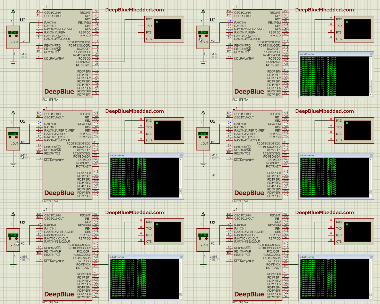
3. Prototyping
Wiring up this schematic on a breadboard should be an easy task. Just upload your firmware hex file to the microcontroller chip. And hook up the input power rails and start testing it up!
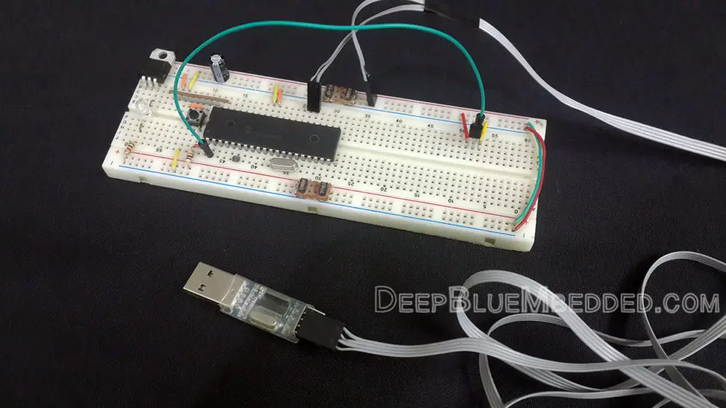
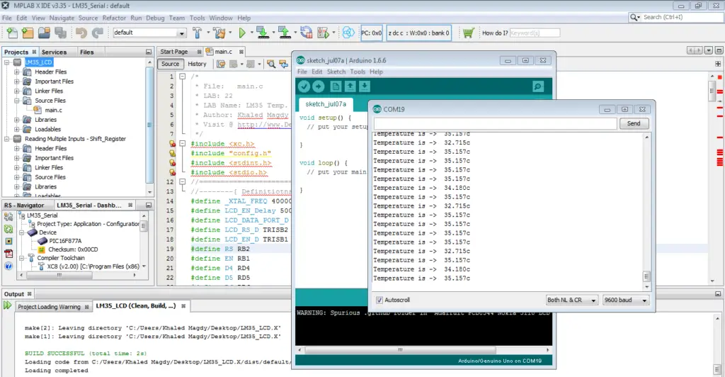
Here is a snapshot for the final output of this LAB. Here I’m using the Arduino’s serial monitor to display the serial data being received by my pc from the microcontroller proto-board
if you’ve found this helpful, then please share it with your network. And good luck for your next projects!
| Previous Tutorial | Tutorial 23 | Next Tutorial | |||||


Problem with second dl link … https://www.mediafire.com/file/ghs9ihg3nxiviwy/LM35_Serial_Project_-_LAB23.rar/file
explain this line ADCON0 |= ANC
Give a look at the datasheet for the adc chapter. You’ll find that the adcon0 register is responsible for choosing the adc channel. And also the numer of channel maps to the value to be written to that register. That’s what we do here