| Previous Tutorial | Tutorial 14 | Next Tutorial | |||||
| CCP Modules | Capture/Compare/PWM | |||||||
| Introductory Level ★☆☆☆☆ | |||||||
In this tutorial, you’ll get to know what are the CCP modules in PIC Microcontrollers. Their modes of operation (Capture-Compare-PWM), what are the mechanics of operation for each mode, And how to develop the necessary firmware in order to drive the CCP module operation for each mode (Capture-Compare). We’ll postpone the PWM mode to the next tutorial. And Now, let’s get started!
[toc]
Components Needed For This Tutorial
| Quantity | Component Name |
| 1 | PIC16F877A |
| 1 | Breadboard |
| 1 | Jumper Wires Pack |
| 4 | 330Ω Resistors |
| 4 | LED |
| 2 | Push Button |
| 2 | 10kΩ Resistors |
| 1 | 4MHz Crystal OSCillator |
| 1 | LM7805 Voltage Regulator |
| 1 | 9v Battery or any Power Supply Source |
| 1 | PICkit3 (PIC Programmer) |
Introducing The CCP Module
This is a multi-purpose module that we can switch between 3 different modes of operation. At each mode of operation, this module can perform a specific task that could be useful for many applications. The Microchip PIC16F877A Chip that we’re using has a couple of identical CCP modules CCP1 & CCP2. They’re actually identical in structure and operation. That’s why we’ll only discuss the CCP1 module and you can replicate everything to drive the CCP2 module if you wish.
Features Of CCP Modules
Each of the Capture/Compare/PWM (CCP) Modules contains a 16-bit register which can operate as a:
- 16-Bit Capture Register
- 16-Bit Compare Register
- PWM Duty Cycle Register
The 16-Bit Data register For CCP modules is actually a couple of 8-Bit SFRs (CCPRxL-CCPRxH) where x maybe 0 or 1 for CCP1 & CCP2 modules.
Modes Of Operation
As we’ve mentioned earlier that each CCP module can operate in one of 3 possible modes. And here is a brief description for each of these modes
Capture: In Capture mode, the CCP module captures the 16-Bit value of Timer1 module in the CCPRx register upon a specific user-defined event. While the Timer1 module is running in either timer-mode or synchronized counter-mode.
Compare: In Compare mode, the 16-Bit value of the CCPRx register is constantly compared against the TMR1 register’s value until a match occurs. Then, the CCPx pin is driven high, low or not-changed as defined by the programmer (you and me).
PWM: In PWM mode, the Timer2 module is being used to produce a PWM output signal on the CCPx pins (RC2, RC3 respectively). We (as programmers) are in charge of setting the output frequency for the PWM signal as well as its duty cycle. The PWM signal is being used for motor speed control, LED dimming, solar chargers and much more as we’ll see in future tutorials.
CCP Modules Timer Resources Required
Both the CCP1 & CCP2 module require a hardware timer as a resource for their operation. The hardware timer module being used for both of CCP modules is determined based on the mode of operation. The table below indicates which timer module is being used for each mode.
| CCP Mode | Timer Resource |
| Capture | Timer1 |
| Compare | Timer1 |
| PWM | Timer2 |
| Note | |||
|
You must pay attention while using CCP modules that there is at least one timer module is running in timer/counter mode and it’s reserved by the CCP module. Any change to hardware timers will directly affect the operation of the respective CCP module, so please be careful! |
|||
CCPxCON Register
The operation of both CCP1 & CCP2 modules is controlled via the CCPxCON Registers which are a couple of 8-Bit SFRs (CCP1CON & CCP2CON) respectively. As we’re going to experiment with the CCP1 module, so we’ll have a look at the register which controls the operation of this module namely CCP1CON. (Datasheet page64)
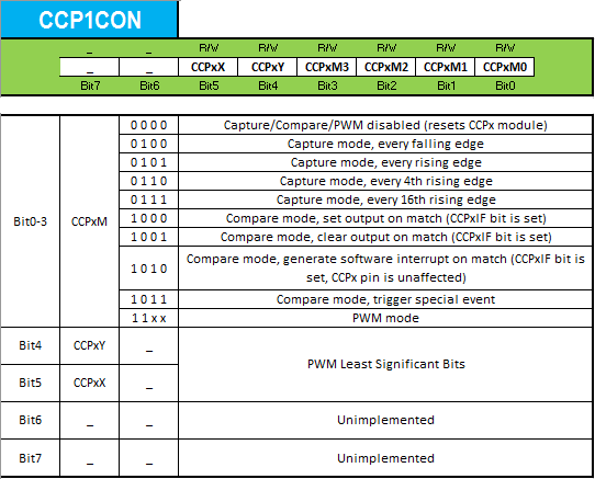
From my own perspective, I can see that the PWM is the most important mode among these 3-modes for CCP modules. There are dozens of applications which are mainly dependent on PWM signals. That’s why we’ll briefly discuss the first two modes (Capture/Compare) in this tutorial. And we’ll only have a single practical LAB for each of them. In order to have much spare time to discuss the PWM mode in more depth. So now let’s get started with the first mode!
Capture Mode
In Capture Mode, the 16-Bit CCPR1 (CCPR1H:CCPR1L) register captures the 16-Bit value of the TMR1 register when an event occurs on the CCP1 pin (RC2). The event that fires a capture signal can be one of the following 4-options:
- Every rising edge
- Every falling edge
- Every 4th rising edge
- Every 16th rising edge
We (the programmers) choose which event is going to fire the capture signal. The type of event that fires the capture signal is configured by the 4-control bits (CCP1M3:CCP1M0) as shown in the CCP1CON register in the datasheet.
Capture Mode Diagram
Here is the logic (Block) diagram for the capture mode as found in the datasheet (8.1 page65)
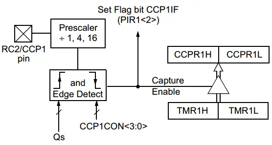
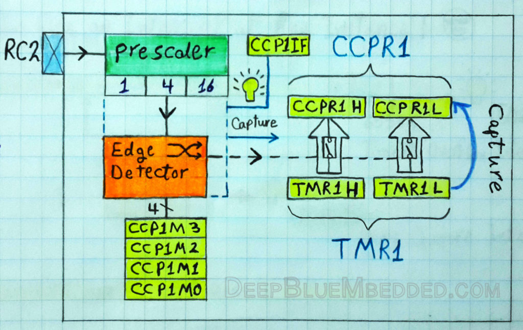
And here is another yet simpler way of representing the same diagram.
CCP Operation In Capture Mode
As you might have noticed in the above diagram, the operation of the CCP module in capture mode goes as follows. First, the timer module is set to operate in timer or counter mode and its register’s value (TMR1) starts incrementing. Second, the CCP module should be configured to operate in capture mode with a selectable trigger event. There are obviously 4-options that fire capture signal (e.g. every rising edge), let’s say every rising edge is selected via the CCP1CON register.
Now, upon each rising edge on the CCP1 pin (RC2). The 16-Bit value of the TMR1 will be copied to the 16-Bit CCPR1 register. This action fires an interrupt signal that is dedicated to the CCP1 module in general. We can actually use this to instantaneously handle CCP-Capture events.
In the following CaptureMode LAB, we’ll operate the Timer1 in counter mode. Then we’ll feed it with some external pulses then trigger the CCP1 pin (RC2) and PORT the CCPR1 register’s value to an io port in order to practically check the operation of this module.
Notes For Capture Mode
I- CCP Pin Configuration:
In Capture mode, the RC2/CCP1 pin should be configured as an input by setting the TRISC2 bit. If the RC2/CCP1 pin is configured as an output, a write to the port can cause a Capture condition.
II- Timer1 Mode Selection:
Timer1 must be running in Timer mode, or Synchronized Counter mode, for the CCP module to use the capture feature. In Asynchronous Counter mode, the capture operation may not work.
III- Software Interrupt:
When the Capture mode is changed, a false capture interrupt may be generated. The user should keep bit CCP1IE clear to avoid false interrupts and should clear the flag bit, CCP1IF, following any such change in operating mode.
IV- CCP Prescaler Setting:
There are four prescaler settings, specified by bits CCP1M3:CCP1M0. Switching from one capture prescaler to another may generate an interrupt.
Configuring CCP1 Module For Capture Mode
- Set Timer1 module to operate in timer/counter mode.
- Turn ON Timer1 module
- Configure the CCP1 module to operate in Capture Mode (using CCP1CON register).
- Choose the event on which a capture occurs (using CCP1CON register – CCP1Mx Bits).
- Configure the CCP1 interrupt
- Write The ISR Handler for CCP-Capture Interrupt
Implementing CCP1 Capture Mode Driver
Step1 – Setup Timer1 For Timer or Counter Mode
[ For Timer Mode ]
|
1 2 3 4 5 6 7 8 |
// -- [[ Configure Timer1 To Operate In Timer Mode ]] -- // Clear The Timer1 Register. To start counting from 0 TMR1 = 0; // Choose the local clock source (timer mode) TMR1CS = 0; // Choose the desired prescaler ratio (1:1) T1CKPS0 = 0; T1CKPS1 = 0; |
[ For Counter Mode ]
|
1 2 3 4 5 6 7 8 9 10 |
//--[ Configure The Timer1 Module To Operate In Counter Mode ]-- TMR1 = 0; // Choose the desired prescaler ratio (1:1) T1CKPS0 = 0; T1CKPS1 = 0; // Choose the extrenal clock source (counter mode) TMR1CS = 1; T1OSCEN = 1; // Enable Synchronization For Counter Mode T1SYNC = 0; |
Step2 – Turn ON Timer1
|
1 |
TMR1ON = 1; |
Step3,4 – Setup CCP1 For Capture Mode & Choose Event
|
1 2 3 4 5 |
//--[ Configure The CCP1 Module To Operate in Capture Mode ]-- CCP1M0 = x; CCP1M1 = x; CCP1M2 = x; CCP1M3 = x; |
Replace x’s with the proper bit-pattern for the capture mode with the event you wish to select.
Step5 – Configure The CCP1 Interrupt
|
1 2 3 4 |
// Enable CCP1 Interrupt CCP1IE = 1; PEIE = 1; GIE = 1; |
Step6 – Write The ISR Handler For CCP-Capture Interrupt
|
1 2 3 4 5 6 7 |
void interrupt ISR() { if (CCP1IF) { // Do Some Stuff... } } |
Compare Mode
In Compare Mode, the 16-Bit CCPR1 (CCPR1H:CCPR1L) register is constantly compared against the TMR1 register. When a match occurs, The CCP1 pin (RC2) is:
- Driven Low
- Driven High
- Remains Unchanged
We (the programmers) choose which event is going to happen on the CCP1/RC2 pin. The action on the CCP1/RC2 pin is controlled by the 4-control bits (CCP1M3:CCP1M0) as shown in the CCP1CON register in the datasheet.
Compare Mode Diagram
Here is the logic (Block) diagram for the compare mode as found in the datasheet (8.2 page66)
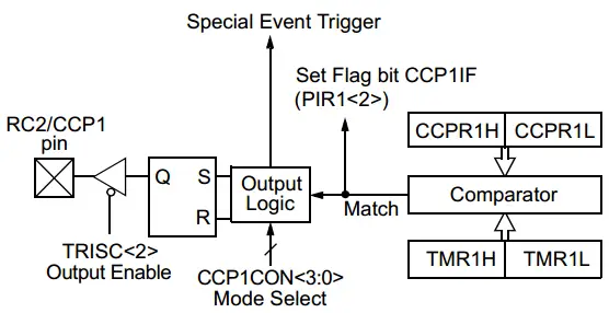
And here is another yet simpler way of the same diagram.
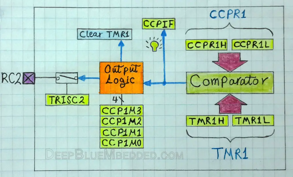
CCP Operation In Compare Mode
As you might have noticed in the above diagram, the operation of the CCP module in compare mode goes as follows. First, the CCPR1 register is loaded by a value at which we want the Timer1 to stop counting. Second, the Timer1 module is set to operate in timer or counter mode and its register’s value (TMR1) starts incrementing. Third, the CCP module should be configured to operate in compare mode with a selectable RC2/CCP1 pin event. There are obviously 3-options for the RC2/CCP1 pin event, let’s say Driven-High is the selected event and it’s easily done via the CCP1CON register.
Now, the Timer1 module is running either in timer/counter mode. When a match occurs, the RC2/CCP1 pin is Driven-High, the timer module is cleared to be zero once again. Moreover, this action also fires an interrupt signal that is dedicated to the CCP1 module. We can actually use this interrupt signal to instantaneously handle CCP-Capture events.
In the following CompareMode LAB, we’ll operate the Timer1 in timer mode. Then we’ll pre-load a specific value to the CCPR1 register to generate a 0.5s time delay for an LED toggle effect.
Notes For Compare Mode
I- CCP Pin Configuration:
The user must configure the RC2/CCP1 pin as an output by clearing the TRISC2 bit. Clearing the CCP1CON register will force the RC2/CCP1 compare output latch to the default low level. This is not the PORTC I/O data latch.
II- Timer1 mode selection:
Timer1 must be running in Timer mode, or Synchronized Counter mode, if the CCP module is using the compare feature. In Asynchronous Counter mode, the compare operation may not work.
III- Software Interrupt Mode:
When Generate Software Interrupt mode is chosen, the CCP1 pin is not affected. The CCPIF bit is set, causing a CCP interrupt (if enabled).
IV- Special Event Trigger:
In this mode, an internal hardware trigger is generated which may be used to initiate an action. The special event trigger output of CCP1 resets the TMR1 register pair. This allows the CCPR1 register to effectively be a 16-bit programmable period register for Timer1. The special event trigger output of CCP2 resets the TMR1 register pair and starts an A/D conversion (if the A/D module is enabled).
Configuring CCP1 Module For Compare Mode
- Set Timer1 module to operate in timer or counter mode.
- Turn ON Timer1 module
- Preload The CCPR1 Register with the desired value (from calculations)
- Configure the CCP1 module to operate in Compare Mode (using CCP1CON register).
- Choose the event on the RC2 pin when a match occurs (using CCP1CON register – CCP1Mx Bits).
- Configure the CCP1 interrupt
- Write The ISR Handler for CCP-Capture Interrupt
Implementing CCP1 Compare Mode Driver
Step1 – Setup Timer1 For Timer or Counter Mode
[ For Timer Mode ]
|
1 2 3 4 5 6 7 8 |
// -- [[ Configure Timer1 To Operate In Timer Mode ]] -- // Clear The Timer1 Register. To start counting from 0 TMR1 = 0; // Choose the local clock source (timer mode) TMR1CS = 0; // Choose the desired prescaler ratio (1:1) T1CKPS0 = 0; T1CKPS1 = 0; |
[ For Counter Mode ]
|
1 2 3 4 5 6 7 8 9 10 |
//--[ Configure The Timer1 Module To Operate In Counter Mode ]-- TMR1 = 0; // Choose the desired prescaler ratio (1:1) T1CKPS0 = 0; T1CKPS1 = 0; // Choose the extrenal clock source (counter mode) TMR1CS = 1; T1OSCEN = 1; // Enable Synchronization For Counter Mode T1SYNC = 0; |
Step2 – Turn ON Timer1
|
1 |
TMR1ON = 1; |
Step3 – Preload The CCPR1 Register
|
1 |
CCPR1 = N; |
Where N is the value that we get from the calculations which will be discussed hereafter in the CompareMode LAB in this tutorial.
Step4,5 – Setup CCP1 For Compare Mode & Choose Event
|
1 2 3 4 5 |
//--[ Configure The CCP1 Module To Operate in Compare Mode ]-- CCP1M0 = x; CCP1M1 = x; CCP1M2 = x; CCP1M3 = x; |
Replace x‘s with the proper bit-pattern for the compare mode with the event you wish to select.
Step6 – Configure The CCP1 Interrupt
|
1 2 3 4 |
// Enable CCP1 Interrupt CCP1IE = 1; PEIE = 1; GIE = 1; |
Step7 – Write The ISR Handler For CCP-Compare Interrupt
|
1 2 3 4 5 6 7 |
void interrupt ISR() { if (CCP1IF) { // Do Some Stuff... } } |
CCP1 In Capture Mode – LAB
| Lab Name | CCP CaptureMode |
| Lab Number | 11 |
| Lab Level | Introductory |
| Lab Objectives | Learn how to use the CCP module in CaptureMode. Run the Timer1 module in synchronized counter mode and increment its value with an external push button input pulses. When the RC2/CCP1 pin is driven-high (Rising edge), the TMR1 counts should be PORTed out to an IO port hooked to some LEDs. |
1. Coding
Open the MPLAB IDE and create a new project name it “CCP-CaptureMode”. If you have some issues doing so, you can always refer to the previous tutorial using the link below.
Set the configuration bits to match the generic setting which we’ve stated earlier. And if you also find troubles creating this file, you can always refer to the previous tutorial using the link below.
Now, open the main.c file and let’s start developing the firmware for our project.
Our objective is to set the Timer1 to operate in the synchronized counter mode so as to get incremented externally via a push button. The CCP1 module should be configured to operate in CaptureMode with rising edge triggered event. When the RC2/CCP1 pin is driven high, the ISR handler should PORT-Out the CCPR1L register to an IO port such as PORTB.
The typical steps for configuring the CCP1 module to operate in CaptureMode have been already discussed earlier in this tutorial. And here is the full code listing for this LAB
|
1 2 3 4 5 6 7 8 9 10 11 12 13 14 15 16 17 18 19 20 21 22 23 24 25 26 27 28 29 30 31 32 33 34 35 36 37 38 39 40 41 42 43 44 45 46 47 48 49 50 51 52 53 54 55 |
/* * LAB Name: CCP-CaptureMode * LAB Number: 11 * Author: khaled_Magdy * Visit DeepBlueMbedded.com For more information */ #include <xc.h> #include "config.h" void main(void) { //--[ Configure The IO Ports ]-- // Set The Output Port For The Capture Operation (CCPR1 register) TRISB = 0x00; PORTB = 0x00; // Initial State // Set The Output Port For The TMR1 Module (TMR1 register) TRISD = 0x00; PORTD = 0x00; // Initial State //--[ Configure The Timer1 Module To Operate In Counter Mode ]-- TMR1 = 0; T1CKPS0 = 0; T1CKPS1 = 0; TMR1CS = 1; T1OSCEN = 1; T1SYNC = 0; TMR1ON = 1; //--[ Configure The CCP1 Module To Operate in Capture Mode ]-- CCP1M0 = 1; CCP1M1 = 0; CCP1M2 = 1; CCP1M3 = 0; // Enable CCP1 Interrupt CCP1IE = 1; PEIE = 1; GIE = 1; // Create The Main Loop Of The System while (1) { // Read & Print Out The TMR1 Counts PORTD = TMR1; } return; } // Write The ISR Handler void interrupt ISR() { if (CCP1IF) { // If Capture Event Occurs, Write the CCPR1 register's value to PORTB PORTB = CCPR1; CCP1IF = 0; } } |
And that’s it. Hit the compile button! and let’s do some testing!
2. Simulation
To simulate this project, you should create a schematic diagram like the one shown below in your simulation environment.
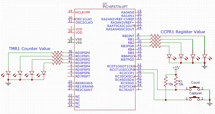
Here are the simulation results in case you’re curious about it. As there is no prototyping on real-board kind of video.
 |
| will be added soon… |
CCP1 In Compare Mode – LAB
| Lab Name | CCP-CompareMode |
| Lab Number | 12 |
| Lab Level | Intermediate |
| Lab Objectives | Learn how to use the CCP module in compare mode in order to generate accurate time intervals utilizing the Timer1 hardware as a resource. We’ll generate a 0.5s time interval to blink an LED in this LAB. |
1. Coding
Open the MPLAB IDE and create a new project name it “CCP-CompareMode”. If you have some issues doing so, you can always refer to the previous tutorial using the link below.
Set the configuration bits to match the generic setting which we’ve stated earlier. And if you also find troubles creating this file, you can always refer to the previous tutorial using the link below.
Now, open the main.c file and let’s start developing the firmware for our project.
Our first task is to compute the number of Timer1 ticks that are required to complete a 0.5s timer interval. We’ll use the following formula.
![]()
Substituting for Fosc = 4MHz, Prescaler = 1:1, Tout = 0.5sec, and solving for Number of Ticks. The result will be as follows
Ticks = 500000
What?! We all know that TMR1 is capped at 65535 ticks, it’s the maximum value for a 16-Bit timer module. That’s why we’ll be in need to generate multiple match events in order to reach the 0.5s time period we wish. Consequently, we’ll plug-in an additional parameter to our equation to be more general as shown below
![]()
Now, let (X=10) you’ll get (Ticks = 50000) which is reasonable indeed. And that is the value which we’ll load into the CCPR1 register. And at which we’ll be triggering the compare event interrupt to flip (Toggle) the LED. The full code listing for this LAB is shown below.
|
1 2 3 4 5 6 7 8 9 10 11 12 13 14 15 16 17 18 19 20 21 22 23 24 25 26 27 28 29 30 31 32 33 34 35 36 37 38 39 40 41 42 43 44 45 46 47 48 49 50 51 52 53 54 55 56 57 58 59 60 61 62 63 64 |
/* * LAB Name: CCP-CompareMode * LAB Number: 12 * Author: khaled_Magdy * Visit DeepBlueMbedded.com For more information */ #include <xc.h> #include "config.h" #include <stdint.h> uint8_t X=0; // Counter For Compare Match Events void main(void) { //--[ Configure The IO Ports ]-- // Set The Output Pin For The LED TRISC4=0; RC4=0; // Initially OFF //--[ Configure The Timer1 Module To Operate In Timer Mode ]-- TMR1 = 0; T1CKPS0 = 0; T1CKPS1 = 0; TMR1CS = 0; TMR1ON = 1; //--[ Configure The CCP1 Module To Operate in Compare Mode ]-- // Preload The CCPR1 Register CCPR1 = 50000; // CCP in Compare Mode, CCPx Pin Is Unchanged & Trigger Special Event CCP1M0 = 1; CCP1M1 = 1; CCP1M2 = 0; CCP1M3 = 1; // Enable CCP1 Interrupt CCP1IE = 1; PEIE = 1; GIE = 1; // Create The Main Loop Of The System while (1) { // Stay Idle, everything is taken care of in the ISR } return; } // Write The ISR Handler void interrupt ISR() { if ( CCP1IF ) { X++; if (X==10) { // Toggle The LED RC4 = ~RC4; X = 0; } // Clear The Interrupt Flag Bit CCP1IF = 0; } } |
And that’s it. Cross Your Fingers! Hit the compile button! and let’s do some testing!
2. Simulation
To simulate this project, you should create a schematic diagram like the one shown below in your simulation environment.
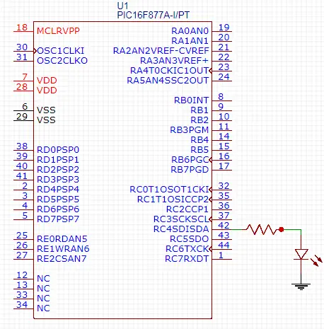
Here are the simulation results in case you’re curious about it. As there is no prototyping on real-board kind of video for this LAB.
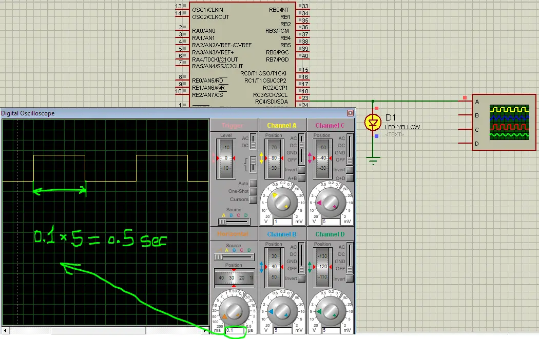
Concluding Remarks
1
With compare mode, we can now fire a Timer1 interrupt signal at any instance. Meaning that we no more need to wait for 65535 ticks until the timer overflows to generate an interrupt. We can now preload any value we want to the CCPR1 register and run the Timer1 module counting from 0 up-to CCPR1 value at which a match event occurs firing a CCP-Interrupt signal. Moreover, it also clears the TMR1 register-pair. The general equation we use for this process is shown below
![]()
Where X is the number of matching interrupts. As you know, for large time intervals (Tout) it’ll require an insanely large amount of Ticks. Which must never exceed 65535 in your calculations, that’s why you should seek for another value for X in these situations.
2
You can set Timer1 to operate in timer mode and utilize the CCP module in capture mode in order to calculate an input wave pulse-width. By starting and stopping the timer on the edges. You must be very careful with this as you might need to flip the CCP mode in the ISR which is a little bit tricky business.
You can set Timer1 to operate in the counter mode and utilize the CCP module in compare mode in order to accept a specific number of external input pulses. You can easily set the threshold by writing to the CCPRx register-pair.
There are many ways in which you can use both capture and compare mode of CCP Modules. Try out the LABs shown above in this tutorial, and then play around to get more familiar with the stuff discussed earlier.
In the next tutorial, we’ll be discussing the PWM Mode. How it works and how to generate PWM signals to control the Brightness of an LED or the speed of a DC Motor or whatever. So let’s move forward!
| Previous Tutorial | Tutorial 14 | Next Tutorial | |||||


Hello Khaled Magdy,
Would you be able to do the same tutorial making use of the MCC generated macros for the CCP peripheral? I would love to see how they correlate and possibly make things easier. I am using a PIC16F18446 nano development board and I am trying to see how everything works in a simple manner.
Greetings Carl,
And thanks for the suggestion. I’ll consider creating a couple of tutorials specifically for using the MCC.
hi in CCB- CaptureMode pgrm: I’m using PIC16F877A MC 20MHZ oscillator. I have chosen the X=50, as per calculations to achive 0.5 sec to toggle RC4 pin. I have checked with Oscilloscope ti’s toggling every 0.1 sec instead of 0.5 sec.
I don’t understand really why it’s happening.
Hey Khaled,
1. I tried your code written in the example of compare mode in PIC18F87J10 but unable to create the waveform as you generated it. Even the register I selected is same as yours.
2. Actually, I am trying to generate a waveform of 150Hz and 200uS Pulse width using ISR, but unable to do so. So, can you please guide me on this problem.